Allied Telesis AT-XS916MXT Installation Manual
Xs916mx series 10 gigabit ethernet switches
Hide thumbs
Also See for AT-XS916MXT:
- Installation manual (148 pages) ,
- Installation manual (96 pages)

Related Manuals for Allied Telesis AT-XS916MXT


Summary of Contents for Allied Telesis AT-XS916MXT
- Page 1 XS916MX Series 10 GIGABIT ETHERNET SWITCHES AT-XS916MXT AT-XS916MXS Installation Guide for Stand-alone Switches 613-002257 Rev. A...
- Page 2 Allied Telesis, Inc. has been advised of, known, or should have known, the...
- Page 3 Electrical Safety and Emissions Standards This section contains the following: “US Federal Communications Commission” “Industry Canada” “Emissions, Immunity and Electrical Safety Standards” on page 4 “Translated Safety Statements” on page 4 US Federal Communications Commission Radiated Energy Note This equipment has been tested and found to comply with the limits for a Class A digital device pursuant to Part 15 of FCC Rules.
-
Page 4: Translated Safety Statements
), EN60950-1 (TUV), EN60825-1 (TUV) Warning Laser Safety: EN60825 Translated Safety Statements Important: The indicates that translations of the safety statement are available in the PDF document “Translated Safety Statements” posted on the Allied Telesis website at alliedtelesis.com/support. -
Page 5: Table Of Contents
Contents Preface ..................................... 11 Document Conventions ..............................12 Contacting Allied Telesis ..............................13 Chapter 1: Overview ................................ 15 Features ..................................16 XS916MX Models ..............................16 100/1000/10000 Mbps Twisted Pair Ports ......................16 SFP/SFP+ Slots ..............................16 S1 and S2 Stacking Ports .............................16 LEDs ..................................16 Installation Options..............................16 MAC Address Table ..............................17... - Page 6 Contents Cabling the Twisted Pair Ports ............................ 50 Installing SFP/SFP+ Transceivers..........................51 Guidelines for SFP/SFP+ Transceivers........................ 51 Installing SFP/SFP+ Transceivers........................52 Chapter 5: Powering On the Switch ..........................55 Powering On the Switch .............................. 56 Monitoring the Initialization Processes ........................58 Configuring the Switch for Stand-alone Operations.....................
- Page 7 Figures Figure 1: AT-XS916MXT Switch Front Panel ........................18 Figure 2: AT-XS916MXS Switch Front Panel ........................18 Figure 3: XS916MX Series Management Panel ........................19 Figure 4: Stacking Transceiver .............................23 Figure 5: LEDs for the Twisted Pair Ports on the XS916MX Series Switch .................25 Figure 6: SFP Slot LEDs ..............................26...
- Page 8 Figures...
- Page 9 Tables Table 1: Twisted Pair Cable for the 100/1000/10000Base-T Ports ..................21 Table 2: LEDs on the Twisted Pair Ports on the XS916MX Series Switch ................25 Table 3: SFP Slot LEDs on the XS916MX Series Switch ....................26 Table 4: S1 and S2 Slot LEDs .............................27 Table 5: Components in the Shipping Box ..........................39 Table 6: Product Dimensions ...............................71 Table 7: Product Weights ..............................71...
- Page 10 Tables...
-
Page 11: Preface
Layer 2+ 10 Gigabit Ethernet switches. This preface contains the following sections: “Document Conventions” on page 12 “Contacting Allied Telesis” on page 13 Note This guide explains how to install the switches as stand-alone units. For instructions on how to install them in a stack configuration with ™... -
Page 12: Document Conventions
Preface Document Conventions This document uses the following conventions: Note Notes provide additional information. Caution Cautions inform you that performing or omitting a specific action may result in equipment damage or loss of data. Warning Warnings inform you that performing or omitting a specific action may result in bodily injury. -
Page 13: Contacting Allied Telesis
XS916MX Series Installation Guide for Stand-alone Switches Contacting Allied Telesis If you need assistance with this product, you may contact Allied Telesis technical support by going to the Support & Services section of the Allied Telesis web site at www.alliedtelesis.com/support. You can find links for the following services on this page: 24/7 Online Support —... - Page 14 Preface...
-
Page 15: Chapter 1: Overview
Chapter 1 Overview This chapter contains the following sections: “Features” on page 16 “Front Panels” on page 18 “Management Panel” on page 19 “100/1000/10000Base-T and Twisted Pair Ports” on page 20 “SFP/SFP+ Slots” on page 22 ... -
Page 16: Features
Features The XS916MX series switches and their features are listed in this section: XS916MX Here are model names of the XS916MX Series switches: Models AT-XS916MXT AT-XS916MXS 100/1000/10000 Here are the basic features of the 100/1000/10000 Mbps twisted pair... -
Page 17: Mac Address Table
XS916MX Series Installation Guide for Stand-alone Switches Wall MAC Address Here are the basic features of the MAC address tables of the switches: Table Storage capacity of 16,000 dynamic MAC address entries Storage capacity of 256 static MAC address entries ... -
Page 18: Front Panels
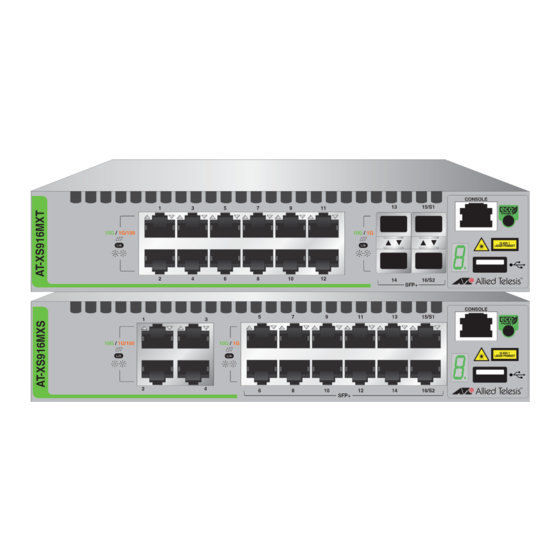
The front panels of the XS916MX Series switches are shown in Figure 1 and Figure 2. 100/1000/10000Base-T Ports SFP Slots Stacking Slots Management Panel Figure 1. AT-XS916MXT Switch Front Panel 100/1000/10000Base-T Ports SFP Slots Stacking Slots Management Panel Figure 2. AT-XS916MXS Switch Front Panel... -
Page 19: Management Panel
XS916MX Series Installation Guide for Stand-alone Switches Management Panel Figure 3 identifies the components in the management panels on the XS916MX Series switches. Console Management Port eco-friendly button Switch ID LED USB Port Figure 3. XS916MX Series Management Panel... -
Page 20: 100/1000/10000Base-T And Twisted Pair Ports
Chapter 1: Overview 100/1000/10000Base-T and Twisted Pair Ports The XS916MXT series switches have 4 or 12 100/1000/10000Base-T ports. Speed The ports can operate at 100 or 1000 Mbps, or 10 Gbps. The speeds may be set manually using the management software or automatically with Auto-Negotiation (IEEE 802.3u), the default setting. -
Page 21: Cable Requirements
XS916MX Series Installation Guide for Stand-alone Switches Cable The cable requirements of the ports are given in Table 1. Requirements Table 1. Twisted Pair Cable for the 100/1000/10000Base-T Ports Cable Type 100Mbps 1000Mbps 10Gbps Standard TIA/EIA 568-B- compliant Category 3 shielded or unshielded cabling with 100 ohm impedance and a frequency of 16 MHz. -
Page 22: Sfp/Sfp+ Slots
Chapter 1: Overview SFP/SFP+ Slots The XS916MX series switch has two SFP/SFP+ slots.You may use the transceivers to connect switches to other network devices over large distances, build high-speed backbone networks between network devices, or connect high-speed devices, such as servers, to your network. Here is a list of supported pluggable transceivers: AT-SP10SR/I ... -
Page 23: Stacking Slots
XS916MX Series Installation Guide for Stand-alone Switches Stacking Slots The S1 and S2 slots on the front panel of the switch are used with special stacking transceivers to create a VCStack of two switches. Here is a list of supported stacking transceivers: AT-SP10TW ... -
Page 24: Eco-Friendly Button
Chapter 1: Overview eco-friendly Button The eco-friendly button on the front panel of the switch is used to toggle the port LEDs on or off. You might turn off the LEDs to conserve electricity when you are not monitoring the device. You can also toggle the LEDs with the ECOFRIENDLY LED and NO ECOFRIENDLY LED commands in the Global Configuration mode of the command line interface. -
Page 25: Leds
XS916MX Series Installation Guide for Stand-alone Switches LEDs This section describes the functions of the LEDs. LEDs for the The twisted pair ports on the XS916MX series switch has one status LED that displays link and activity information. The LEDs are shown in Figure 5. Twisted Pair Ports Status LED for the Top Port... -
Page 26: Leds For The Stacking Slots
Chapter 1: Overview Status LED for the Top Port Status LED for the Bottom Port Figure 6. SFP Slot LEDs The LEDs are described in Table 3. Table 3. SFP Slot LEDs on the XS916MX Series Switch State Description The slot is empty, the SFP transceiver has not established a link to a network device, or the LEDs are turned off. -
Page 27: Switch Id Led
XS916MX Series Installation Guide for Stand-alone Switches Table 4. S1 and S2 Slot LEDs State Description Link/Activity The slot is empty, the stacking transceiver has not established a link to a network device, or the LEDs are turned off. To turn on the LEDs, use the eco-friendly button. -
Page 28: Figure 8: Switch Id Led Not In Low Power Mode
Chapter 1: Overview The switch is booting up. The switch has encountered a fault condition. The switch is operating as a stand-alone unit, with the ID number 0. The switch has an ID number of 1 or 2 as part of a VCStack. The dot in the lower right corner flashes when the switch accesses USB memory. -
Page 29: Usb Port
XS916MX Series Installation Guide for Stand-alone Switches USB Port The management panel has a USB port. You may use the port to store configuration files on flash drives and to restore configuration files to switches whose settings have been lost or corrupted, or to quickly configure replacement units. -
Page 30: Console Port
Chapter 1: Overview Console Port The Console port is used to conduct management sessions with the switch to configure its features and parameter settings. This type of management uses serial RS-232 and is commonly referred to as local or out-of-band management because it is not conducted over your network. To perform local management, you must be at the location of the switch and must use the management cable included with the switch. -
Page 31: Power Supply
XS916MX Series Installation Guide for Stand-alone Switches Power Supply The XS916MX series switches come with one AC power supply. The back panels have one AC connector. The power supply is not field-replaceable; refer to “Technical Specifications” on page 71 for the input voltage range. Warning Power cord is used as a disconnection device. - Page 32 Chapter 1: Overview...
-
Page 33: Chapter 2: Beginning The Installation
Chapter 2 Beginning the Installation The chapter contains the following sections: “Reviewing Safety Precautions” on page 34 “Choosing a Site for the Switch” on page 38 “Unpacking the Switch” on page 39 ... -
Page 34: Reviewing Safety Precautions
Chapter 2: Beginning the Installation Reviewing Safety Precautions Review the following safety precautions before beginning the installation procedure. Note Safety statements that have the symbol are translated into multiple languages in the Translated Safety Statements document at www.alliedtelesis.com/support. Warning Class 1 Laser product. - Page 35 XS916MX Series Installation Guide for Stand-alone Switches Warning Class I Equipment. This equipment must be earthed. The power plug must be connected to a properly wired earth ground socket outlet. An improperly wired socket outlet could place hazardous voltages on accessible metal parts. ...
- Page 36 Use dedicated power circuits or power conditioners to supply reliable electrical power to the device. Caution The chassis may be heavy and awkward to lift. Allied Telesis recommends that you get assistance when mounting the chassis in an equipment rack. ...
- Page 37 XS916MX Series Installation Guide for Stand-alone Switches Warning To reduce the risk of electric shock, the PoE ports on this product must not connect to cabling that is routed outside the building where this device is located. Caution The unit does not contain serviceable components. Please return damaged units for servicing.
-
Page 38: Choosing A Site For The Switch
Chapter 2: Beginning the Installation Choosing a Site for the Switch Observe these requirements when planning the installation of the switch. If you plan to install the switch in an equipment rack, check to be sure that the rack is safely secured so that it will not tip over. Devices in a rack should be installed starting at the bottom, with the heavier devices near the bottom of the rack. -
Page 39: Unpacking The Switch
XS916MX Series Installation Guide for Stand-alone Switches Unpacking the Switch The XS916MX series switch comes with the components listed in Table 5. Note If any item is missing or damaged, contact your Allied Telesis sales representative for assistance. Table 5. Components in the Shipping Box Name... - Page 40 Table 5. Components in the Shipping Box (Continued) Name Item 4 X Bracket Wall mount bracket kit 16 M4x6mm screw Note You should retain the original packaging material in the event you need to return the unit to Allied Telesis.
-
Page 41: Chapter 3: Installing The Switch
Chapter 3 Installing the Switch The procedures in this chapter are: “Installing the Switch on a Table” on page 42 “Installing the Switch in an Equipment Rack” on page 43 “Installing the Switch on a Wall” on page 46 ... -
Page 42: Installing The Switch On A Table
Chapter 3: Installing the Switch Installing the Switch on a Table This section contains the procedure for installing the switch on a table or desk. Note The rubber feet on the bottom of the chassis should be left on for table installation. -
Page 43: Installing The Switch In An Equipment Rack
XS916MX Series Installation Guide for Stand-alone Switches Installing the Switch in an Equipment Rack You can install one XS916MX series switch in a row of the equipment rack or two XS916MX series switches in one row of the equipment rack as shown in Figure 10. -
Page 44: Figure 11: Turning The Switch Upside Down
Chapter 3: Installing the Switch Caution The chassis may be heavy and awkward to lift. Allied Telesis recommends that you get assistance when mounting the chassis in an equipment rack. 1. Review “Choosing a Site for the Switch” on page 38 to verify the suitability of the site for the switch. -
Page 45: Figure 14: Installing The Brackets On The Switch
XS916MX Series Installation Guide for Stand-alone Switches 6. Attach the two rack mount brackets to the sides of the switch with the eight bracket screws as shown in Figure 14. Figure 14. Installing the Brackets on the Switch 7. While another person holds the switch in the equipment rack, secure it with standard equipment rack screws as shown in Figure 15. -
Page 46: Installing The Switch On A Wall
Chapter 3: Installing the Switch Installing the Switch on a Wall The XS916MX series switch must be mounted on the wall in portrait orientation with the front panel facing left or right. See Figure 16. Figure 16. Positions of the XS916MX Series Switch on a Wall What to Prepare You need the following items to install the switch on a wall: for Wall... -
Page 47: Installing The Switch On A Wall
XS916MX Series Installation Guide for Stand-alone Switches Installing the To install the XS916MX series switch on a wall, perform the following procedure: Switch on a Wall 1. Review “Choosing a Site for the Switch” on page 38 before performing this procedure. 2. -
Page 48: Figure 20: Installing The Switch On The Wall
Chapter 3: Installing the Switch 5. Using a flat-head screwdriver, remove the rubber feet from the bottom of the switch. See Figure 20. Figure 20. Installing the Switch on the Wall... -
Page 49: Chapter 4: Cabling The Networking Ports
Chapter 4 Cabling the Networking Ports This chapter contains the following procedures: “Cabling the Twisted Pair Ports” on page 50 “Installing SFP/SFP+ Transceivers” on page 51 ... -
Page 50: Cabling The Twisted Pair Ports
Chapter 4: Cabling the Networking Ports Cabling the Twisted Pair Ports Here are the guidelines to cabling the 100/1000/10000Base-T twisted pair ports: The cable specifications for the twisted pair ports are listed in Table 1 on page 21. The connectors on the cables should fit snugly into the ports, and ... -
Page 51: Installing Sfp/Sfp+ Transceivers
XS916MX Series Installation Guide for Stand-alone Switches Installing SFP/SFP+ Transceivers This section contains guidelines and procedures for installing SFP/SFP+ transceivers. Guidelines for Here are general installation guidelines for SFP/SFP+ transceivers: SFP/SFP+ SFP/SFP+ transceivers are hot-swappable. You may install them Transceivers while the chassis is powered on. -
Page 52: Installing Sfp/Sfp+ Transceivers
Chapter 4: Cabling the Networking Ports Installing SFP/ To install SFP/SFP+ transceivers, perform the following procedure: SFP+ 1. Remove the dust plug from a transceiver slot on the switch. See Transceivers Figure 21. Figure 21. Removing the Dust Plug from an SFP/SFP+ Slot 2. -
Page 53: Figure 23: Removing The Dust Cover From An Sfp Transceiver
XS916MX Series Installation Guide for Stand-alone Switches 5. Remove the dust cover from the transceiver, as shown in Figure 23. Figure 23. Removing the Dust Cover from an SFP Transceiver 6. Verify the position of the handle on the SFP transceiver. For a top slot, the handle is in the upright position, as shown in Figure 24. -
Page 54: Figure 25: Connecting A Fiber Optic Cable To An Sfp Transceiver
Chapter 4: Cabling the Networking Ports 7. Connect the fiber optic cable to the transceiver, as shown in Figure 25. The connector on the cable should fit snugly into the port, and the tab should lock the connector into place. Figure 25. -
Page 55: Chapter 5: Powering On The Switch
Chapter 5 Powering On the Switch This chapter contains the following procedures: “Powering On the Switch” on page 56 “Monitoring the Initialization Processes” on page 58 “Configuring the Switch for Stand-alone Operations” on page 61 “Specifying Ports in the Command Line Interface for Stand-alone ... -
Page 56: Powering On The Switch
Chapter 5: Powering On the Switch Powering On the Switch Before powering on the switch, see “Power Specifications” on page 72 for the power specifications. To install the power cord retaining clip and power on the switch, perform the following procedure: 1. -
Page 57: Figure 28: Plugging In The Ac Power Cord
XS916MX Series Installation Guide for Stand-alone Switches 3. Connect the power cord to the connector. See Figure 28. Figure 28. Plugging in the AC Power Cord 4. Lower the retaining clip to secure the power cord to the switch. See Figure 29. -
Page 58: Monitoring The Initialization Processes
/ /______\ \ \_ __/ /| ______ | | ______ | \ ____ / /______/\____\ \/ /____________/ Allied Telesis Inc. AlliedWare Plus (TM) v0.0.0 Current release filename: xs900-main-20151028-4.rel Built: Wed Oct 28 06:23:09 UTC 2015 Mounting static filesystems... Checking flash filesystem... -
Page 59: Figure 31: Switch Initialization Messages (Continued)
XS916MX Series Installation Guide for Stand-alone Switches Mounting flash filesystem... Checking for last gasp debug output... Checking NVS filesystem... Mounting NVS filesystem... Starting base/arm_sysctl... Starting base/dbus... Starting base/syslog... Starting base/loopback... Starting base/poe_done... Starting base/sysctl... Starting base/portmapper... Received event syslog.done Starting base/reboot-stability... Checking system reboot stability... -
Page 60: Figure 32: Switch Initialization Messages (Continued)
Chapter 5: Powering On the Switch Initializing HA processes: atmfd, auth, cntrd, epsr, hostd, hsl, imi imiproxyd, lacp, lldpd, loopprot, mstp, nsm, ripd rmon, sflowd, udldd Received event network.initialized Assigning Active Workload to HA processes: hsl, nsm, authd, epsrd, lacpd, lldpd, loopprotd mstpd, rmond, sflowd, imi, imiproxyd Received event network.activated Loading default configuration... -
Page 61: Configuring The Switch For Stand-Alone Operations
XS916MX Series Installation Guide for Stand-alone Switches Configuring the Switch for Stand-alone Operations After the switch has initialized its management software, examine the switch ID LED on the front panel and do one of the following: If the LED is displaying “0,” the installation procedure is complete. ... -
Page 62: Figure 33: Connecting The Management Cable To The Console Port
Chapter 5: Powering On the Switch Figure 33. Connecting the Management Cable to the Console Port 2. Connect the other end of the cable to an RS-232 port on a terminal or PC with a terminal emulator program. 3. Configure the terminal or terminal emulator program as follows: Baud rate: 9600 bps (The baud rate of the Console Port is ... -
Page 63: Disabling Vcstack
XS916MX Series Installation Guide for Stand-alone Switches Disabling To disable the VCStack feature to use the switch as stand-alone unit, perform the following procedure: VCStack Caution Disabling the VCStack feature requires resetting the switch. If the switch is already connected to a live network, some network traffic may be lost. -
Page 64: Figure 36: Moving To The Global Configuration Mode
Chapter 5: Powering On the Switch 3. Review the following items: If the Operational Status is “Stacking Hardware Disabled,” the VCStack feature is already disabled on the switch. The switch is ready for operations as a stand-alone switch in your network. No further installation steps are required. -
Page 65: Figure 38: Returning To The Privileged Exec Mode
XS916MX Series Installation Guide for Stand-alone Switches 7. Enter the EXIT command to return to the Privileged Exec mode, as shown in Figure 38. awplus(config)# exit awplus# Figure 38. Returning to the Privileged Exec Mode 8. Enter the WRITE command to save your change in the configuration file. -
Page 66: Specifying Ports In The Command Line Interface For Stand-Alone Switches
Chapter 5: Powering On the Switch Specifying Ports in the Command Line Interface for Stand-alone Switches The command line interface in the management software on the switch has a parameter that you use to specify the individual ports. The parameter is the PORT parameter, and Figure 40 shows its format. port1 Stack ID Module ID... -
Page 67: Chapter 6: Troubleshooting
This chapter contains suggestions on how to troubleshoot the switch if a problem occurs. Note For further assistance, please contact Allied Telesis Technical Support at www.alliedtelesis.com/support. Problem 1: The Switch ID LED on the front of the switch is off. - Page 68 Chapter 6: Troubleshooting Try connecting another network device to the twisted pair port with a different cable. If the twisted pair port is able to establish a link, then the problem is with the cable or the other network device. Verify that the twisted pair cable does not exceed 100 meters (328 ...
- Page 69 The internal temperature of the switch has exceeded the normal operating range, and the switch may shut down. Contact your Allied Telesis sales representative for assistance. Problem 8: The AT-GS924MPX or AT-GS948MPX Switch is not providing power to a PoE device.
- Page 70 Chapter 6: Troubleshooting is carried on pins 4, 5, 7, and 8 on the RJ-45 port, the same pins that carry the network traffic. The other mode, Alternative A, defines pins 1, 2, 3, and 6 as the power carriers. The AT-GS924MPX and AT-GS948MPX Switches do not support Alternative A.
-
Page 71: Appendix A: Technical Specifications
"RJ-45 Style Serial Console Port Pinouts” on page 75 Physical Specifications Dimensions (H x W x D) Table 6. Product Dimensions AT-XS916MXT 4.3 cm x 21 cm x 32.3 cm (1.7 in. x 8.3 in. x 12.7 in.) AT-XS916MXS 4.3 cm x 21 cm x 32.3 cm (1.7 in. -
Page 72: Environmental Specifications
Storage Humidity 5% to 95% noncondensing Maximum Operating Altitude 3,000 m (6,562 ft) Power Specifications Input Voltages Table 10. Input Voltages AT-XS916MXT Voltage: 100-240 VAC, 1.0A Frequency: 47-63 Hz AT-XS916MXS Voltage: 100-240 VAC, 1.0A Frequency: 47-63 Hz Maximum Power Consumption Table 11. -
Page 73: Certifications
XS916MX Series Installation Guide for Stand-alone Switches Certifications Table 13. Product Certifications RFI Emissions FCC Class A, EN55022 Class A, EN61000-3-2, EN61000-3-3, VCCI Class A, RCM EMC (Immunity) EN55024 UL 60950-1 ( Electrical and Laser Safety CSA-C22 No. 60950-1 ( EN60950-1 (TUV), EN60825-1 (TUV) -
Page 74: Rj-45 Twisted Pair Port Pinouts
Appendix A: Technical Specifications RJ-45 Twisted Pair Port Pinouts Figure 41 illustrates the pin layout of the RJ-45 connectors and ports. Figure 41. RJ-45 Socket Pin Layout (Front View) Table 14 lists the pin signals for 10 and 100 Mbps. Table 14. -
Page 75: Rj-45 Style Serial Console Port Pinouts
XS916MX Series Installation Guide for Stand-alone Switches Table 15. Pin Signals for 1000 Mbps (Continued) Pinout Pair Pair 3 - Pair 2 - Pair 4 + Pair 4 - RJ-45 Style Serial Console Port Pinouts The pin signals of the RJ-45 style serial Console port are listed in Table 16. - Page 76 Appendix A: Technical Specifications...
Need help?
Do you have a question about the AT-XS916MXT and is the answer not in the manual?
Questions and answers