Table of Contents
Advertisement
Quick Links
Advertisement
Table of Contents

Related Manuals for Veripos HEXAGON LD8


Summary of Contents for Veripos HEXAGON LD8
- Page 1 Operations Manual AB-V-MA-00635_RevA7 19 January 2022...
-
Page 2: Table Of Contents
Configuration and operation ............................. 13 WebUI status ..............................13 LD8 password ..............................15 L-band configuration ............................15 Activation and deactivation of VERIPOS services ....................18 Calculation configuration ............................. 19 Ethernet configuration ............................21 Output configuration ............................23 Input configuration............................... 28 Rolling log ................................ -
Page 3: Introduction
Throughout this manual, references are made to the VERIPOS Helpdesk. The Helpdesk is a service provided as first point of contact for all VERIPOS technical enquiries and fault reports. It is manned 24 hours per day, 365 days per year. Full contact details are listed in the Contact information section. -
Page 4: Activating Veripos Correction Services
1.5 Activating VERIPOS correction services VERIPOS correction signals are provided as a chargeable service. In order for the LD8 to decode corrections and output a corrected position, it must be activated. The user can send a request for an activation of services to the VERIPOS Helpdesk and the activation will then be sent via L-band satellite to the requested unit. -
Page 5: Terms And Abbreviations
Internet Protocol IPv4 Internet Protocol version 4 Local Area Network L-band Signal transmitted to carry correction data to mobile users VERIPOS receiver containing combined L-band and GNSS card Light Emitting Diode NMEA National Marine Electronics Association PDOP Positional Dilution of Precision... -
Page 6: Document Conventions
Introduction 1.7 Document conventions Typographical conventions Italic or bold text is used to emphasize certain information. Italic is also used in cross-references to other parts of the document and to other documents. Bold text is also used for indicators and touch screen “push-buttons” commands. “Text within quotes”... -
Page 7: Waste Electrical And Electronic Equipment
WEEE directive by banning the presence of specific hazardous substances in the products at the design phase. The WEEE directive covers all VERIPOS products imported into the EU as of August 13, 2005. EU-based manufacturers, distributors, retailers and importers are obliged to finance the costs of recovery from municipal collection points, reuse, and recycling of specified percentages per the requirements contained in the WEEE Directive. -
Page 8: Disclaimer
Manual or its contents has been permitted by VERIPOS in accordance with this disclaimer, then no changes in the Manual or deletion of any kind to the Manual may be made. You acknowledge that you do not acquire any ownership rights by accessing, viewing or utilising this Manual and agree that you shall not hold itself out to any third party as having any ownership rights to this Manual. -
Page 9: Hardware Overview
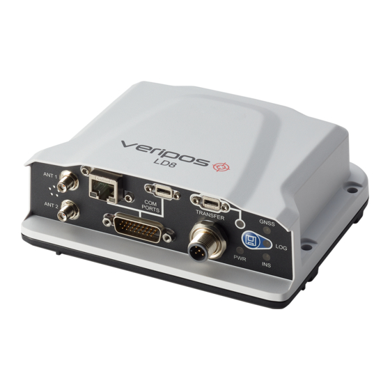
2.1 Overview and description • The LD8 is a small, lightweight and low power system. • VERIPOS provide a +9 to +36 VDC power supply with the LD8. • The unit incorporates front panel LED indicators for status monitoring. •... - Page 10 Hardware overview LOG LED State Description LD8 is connected to a computer as a mounted device Logging to internal memory Green blink Green solid Internal logging stopped Green/Yellow Logging to internal memory with low memory available alternating blink Yellow solid Internal logging stopped with low memory available Yellow fast blink Memory is busy...
-
Page 11: Interface Panel Connections
Hardware overview 2.3 Interface panel connections This section details the antenna and data connectivity available from the LD8 interface panel. Coaxial The LD8 interface panel is fitted with two SMA antenna connectors labelled ANT 1 and ANT 2: Interface panel of LD8 with two SMA antenna connectors •... -
Page 12: Ethernet And Webui Connection
Google Chrome is required to configure the LD8 for operation. Both Microsoft Edge and Internet Explorer come pre-loaded onto VERIPOS PCs when issued with the unit. The LD8 is shipped with a factory default IP address of 192.168.2.8. The connecting PC or laptop should be configured to use the same IP subnet. -
Page 13: Configuration And Operation
4 Configuration and operation There are two ways in which the LD8 can be configured, by using VERIPOS Quantum software, or by using the LD8 WebUI. Quantum must be used if being used for system monitoring. If Quantum is not available, system configuration must be performed through the WebUI, which features a terminal application that can be used for sending commands. - Page 14 Configuration and operation WebUI Status page items At the top of the page is a summary bar containing key system information. Below this, the main body of the LD8 WebUI Home > Status page is split into several boxes, with each box containing useful system information: Item Description Information relating to the operating mode, calculated position type, latitude, longitude,...
-
Page 15: Ld8 Password
FRESET USER_ACCOUNTS 4.3 L-band configuration Tracking of an L-band beam is required to receive VERIPOS service correction and activation data. This section will detail how to establish and confirm successful L-band tracking to make use of VERIPOS services. Auto Beam is the recommended way to manage L-band beam choices. When in this mode, the LD8 will track up to three beams simultaneously with tracking determined based on available L-band satellites and elevation. - Page 16 Verichart can be used to assess L-band availability by creating coverage charts specific to a work location. Where possible, different VERIPOS receiver units on the same vessel should be set to different beams to maximise redundancy. Selecting beam via WebUI To select Auto beam (or a single beam if required) navigate to Configuration >...
- Page 17 A custom L-band beam name and frequency (in Hz) can be manually entered, however this should be used only under the instruction of VERIPOS support. The format for assigning a user L-band beam is as follows: ASSIGNLBANDBEAM MANUAL BEAMNAME FREQUENCY 1200...
-
Page 18: Activation And Deactivation Of Veripos Services
If in doubt as to the LD8 unit ID and/or the activation service code enter the following: LOG VERIPOSINFO The LD8 unit ID is required for VERIPOS to activate services and each activation/deactivation is unique to each unit ID. The activation service code can be used to determine what services the unit is activated to receive. -
Page 19: Calculation Configuration
The LD8 is capable of tracking and using correction data from Satellite Based Augmentation Systems (SBAS). If SBAS is enabled a SBAS DGNSS solution will be output in the event of VERIPOS solutions failure. To enable/disable SBAS navigate to Configuration > Positioning and click Receive (Rover), followed by Next. - Page 20 Configuration and operation SBAS configuration via terminal The LD8 SBAS mode can be enabled or disabled via the terminal. The SBAS positioning mode can be enabled by entering: SBASCONTROL ENABLE AUTO The SBAS positioning mode can be disabled by entering: SBASCONTROL DISABLE Heading offset and output frequency via WebUI The heading offset and the heading output rate can be configured within the WebUI by navigating to...
-
Page 21: Ethernet Configuration
Configuration and operation 4.6 Ethernet configuration Network connectivity to the LD8 is essential for configuration and implementing changes. The following sub- sections detail how to check and change the present IP address settings. IP configuration via WebUI IP addresses can be checked and configured by navigating to Settings > Networking. Within the Ethernet Window, the DHCP setting can be toggled to Off or On. - Page 22 Configuration and operation Setting a static IP via terminal The LD8 is preconfigured with a static IP of 192.168.2.8, however this IP address can be changed to a different static IP address. The command to change to a static IP follows the structure of: IPCONFIG [interface_name] [address_mode] [IP_address] [netmask] [gateway] Example for this: IPCONFIG ETHA STATIC 192.168.2.8 255.255.255.0 192.168.2.1...
-
Page 23: Output Configuration
Configuration and operation 4.7 Output configuration The LD8 is capable of outputting VERIPOS RTCM data and a selection of message formats via the following: TCP/IP Serial • Serial outputs are available for reference within commands or selected in the WebUI by using ‘COM1’, ‘COM2’... - Page 24 Configuration and operation Configuring message outputs via WebUI Navigate to Configuration > Ports, where configuration of COM 1-3, ICOM 1-3 and USB 1-3 ports is available. Using command variables to specify message type, enter the appropriate command variable next to the required COM, ICOM or USB port in the Messages field.
- Page 25 Configuration and operation Message output rate via WebUI Once a NovAtel command variable has been specified a cog wheel will appear within the right hand corner of the Messages field: Clicking on the settings cog will open a Message Settings window where an output rate can be specified in the Period field.
- Page 26 Configuration and operation Setting GGA precision selection via terminal It is possible to configure the number of decimal places used in the Latitude and Longitude fields output in the GGA Message. The precision can be set to 5, 6, 7 or 8. When changing the precision value, the same value should be applied to both the Longitude and Latitude.
- Page 27 Configuration and operation Enabling VERIPOS RTCM output via terminal RTCM can be output on any of the LD8 serial COM ports. Within the terminal window enter the commands below where updating COM1 with the desired output COM port number. UNLOGALL COM1...
-
Page 28: Input Configuration
To input external corrections, it is required to issue two commands to the unit. These two commands will configure the required baud rate of input and then set the port for decoding of VERIPOS RTCM data. These commands are SERIALCONFIG and INTERFACEMODE. -
Page 29: Rolling Log
Select All option followed by clicking the Download icon ( ) to download all available files. If requested to provide logs by VERIPOS Support, ensure that the logs cover the period that needs analysing plus 3 hours prior to the event and 1 hour after. -
Page 30: Factory Reset
4.10 Factory reset A factory reset can be performed to revert the LD8 back to default factory settings. This should only be carried out under the advice of VERIPOS Support. Factory resetting via terminal A factory reset should be performed by issuing the case sensitive command: LUA START factoryreset.lua... -
Page 31: Reference Information
Reference information 5 Reference information 5.1 Commands list index Commands used within this manual are listed below. Highlighted text should be changed as required. Command Description The format for assigning a specific L-band ASSIGNLBANDBEAM beam Setting for automatically tracking L-band ASSIGNLBANDBEAM AUTO beams GGAQUALITY 4 OUT_OF_BOUNDS 2 WAAS 2 PPP... -
Page 32: Ld8 Output Sentences
• • TRINAV VERIPOS UKOOA 5.3 NMEA talker IDs The NMEA talker identifier serves to define the nature of the data being transmitted. The talker is the first 2 characters after the $ sign within the NMEA sentence. As the LD8 is capable of utilising more than only the GPS constellation, the talker has a set value for each constellation. - Page 33 Reference information GGA sentence The NMEA GGA sentence contains time and position fix related data for a GPS system. It includes basic quality information, which is limited to ‘Fix Quality’, ‘Number of Satellites in Use’, ‘HDOP’ and ‘Age of Corrections’. GGA sentence structure &...
- Page 34 Reference information GST sentence The NMEA GST sentence provides error statistics of the position fix. These statistics follow from the position calculation process. GST sentence structure & example $GNGST, hhmmss.ss, a.aa, b.bb, c.cc, d.dddd, e.ee, f.ff, g.gg *hh $GNGST, 024603.00, 1.47, 0.11, 0.07, 28.3688, 0.10, 0.08, 0.16 *58 GST sentence defined Field Content...
- Page 35 Reference information GSA sentence The NMEA GSA sentence contains the GNSS receiver operating mode, active satellites used in the navigation solution, and DOP values. GSA sentence structure & example $GNGSA, a, 1, cc, cc, cc, cc, cc, cc, cc, cc, cc, cc, cc, cc, d.d, e.e, f.f *hh $GNGSA, a, b, 02, 12, 15, 20, 21, 24, 25, 29, 32, , 1.7, 0.9, 1.5 *58 GSA sentence defined...
- Page 36 Reference information GSV sentence The NMEA GSV sentence provides information relating to the number of satellites (SV) in view, satellite ID numbers, elevation, azimuth, and SNR value in one sentence. GSV sentence structure & example $GPGSV, a, b, cc, dd, ee, fff, gg, dd, ee, fff, gg, dd, ee, fff, gg, dd, ee, fff, gg, *hh, $GPGSV, 4, 1, 13, 02, 10, 043, 41, 05, 05, 103, 38, 10, 04, 238, 42, 12, 13, 030, 44, *7E, (Satellite 1) (Satellite 2)
- Page 37 Reference information GRS sentences The NMEA GRS sentence provides range residuals for each satellite. GRS sentence structure & example $GNGRS, hhmmss.ss, a, b.b, b.b, b.b, b.b, b.b, b.b, b.b, b.b, b.b, b.b, b.b, b.b, ,cc ,dd *67 $GNGRS, 142406.00, 1, -1.1, -0.1, 1.7, 1.2, -2.0, -1.3, 1.3, -0.4, -1.2, -0.2, , 1, 1, *hh GRS sentence defined Field...
- Page 38 Reference information RMC sentences The NMEA RMC sentence provides essential GPS PVT (position, velocity, time) data. RMC sentence structure & example $GNRMC, hhmmss.ss, a, ddmm.mmmmmmm, b, dddmm.mmmmmmm, c, dd.ddd, eee.e, ddmmyy f.f, g, h *hh $GNRMC, 143909, A, 5107.0020216, N, 11402.3294835, W, 0.036, 348.3, 210307, 0.0, E, D *31 RMC sentence defined Field...
- Page 39 Reference information TRINAV sentences (V3 & V4) TRINAV version 3 sentence example [WGPOS,3,1,OEM7VERI,APEX5,OM7MR0702AN0006,1041,392609.00,0.0,57 12.08207N,002 11.53782W,114.421,0.7,1.2,,0.005948,0.000899,0.004640,0.030111,0.14,3,1,3,16,0,1,8,10,11,14,20,22,27,28, 32,65,66,67,73,81,82,] TRINAV version 3 sentence defined Content Format Unit Notes Start character $WGPOS Format version = 3 for this version Nav. point no. See comment 1 System name/version Name + version of DGPS system.
- Page 40 Reference information TRINAV version 3 definitions commentary 1. The "Nav point no." is a unique integer identifying the position. It should be manually entered into the software according to requests from Positioning Engineers. Alternatively, this should start from 1 and be incremented if several positions are output from the same system.
- Page 41 Reference information TRINAV version 4 sentence example [WGPOS,4,1,OEM7VERI,APEX5,OM7MR0702AN0006,1041,396729.00,0.0,57 12.08195N,002 11.53806W,113.340,0.7,0.9,,0.285460,0.009316,0.156003,0.663714,1.33,3,2,G,R,1,0,0,0,1,M3,IOR,25E,AOR W,18,2,G01,G03,G08,G10,G11,G14,G17,G18,G22,G28,G32,R02,R03,R09,R11,R17,R18,R19,777,706,] TRINAV version 4 sentence defined Content Format Unit Notes Start character $WGPOS Format version = 4 for this version Nav. point no. See comment 2 System Application name and version, space separated e.g. Quantum 3.0.0.0 Service level Highest enabled service permitted e.g.
- Page 42 If values other than those given above are used, this must be explicitly stated by the contractor. c. VERIPOS statistics are implemented as per the IMCA/OGP ‘Guidelines for GNSS positioning in the oil & gas industry’ Report No. 373-19 or IMCA S015, June 2011, unless otherwise indicated.
- Page 43 Reference information 8. TRINAV V4 correction source codes: Type code Meaning L-band only, always followed by 1 (i.e. L1) L-band multi-channel, followed by number of links tracked (e.g. M3) Internet source, always followed by 0 (i.e. I0) Other, always followed by 0 (i.e. O0) LD8 Operations Manual...
- Page 44 Reference information VERIPOS UKOOA sentences The VERIPOS UKOOA sentence is compliant with OGP 373-19 and IMCA S015 (July 2011). For further information relating to these standards please visit https://www.iogp.org and https://www.imca-int.com. VERIPOS UKOOA sentence structure & example [ 240 7300 VERI 1 2067 295238.0 +0.1 +8.0 057 12.08207N 002 11.53776W 63.997 +50.40 1.151 0.564 1.004 7 0.025 0.054 0.14 0.001 0.000 0.000 0.003 0.06 0.05 6.5 P 15{ 20 27 13 30 26 8 21 16 7 10...
- Page 45 Reference information Field Content Notes be detected) and the Significance level used. The Variance and Covariance terms are elements from the variance-covariance 126…130 Unit Variance matrix of the position fix computation (un-scaled) in metres². 131…137 Variance Latitude 138…145 Covariance Lat/Long 146…152 Variance Longitude 153…159 Variance Height 95% Error Ellipse Semi...
-
Page 46: Contact Information
Contact information 6 Contact information All initial contacts regarding technical or support issues should be addressed to the VERIPOS Helpdesk. Where appropriate the Helpdesk will refer issues to the regional operations and engineering teams. 6.1 VERIPOS Helpdesk details VERIPOS support system https://help.veripos.com... -
Page 47: Appendix
Appendix 7 Appendix 7.1 L-band coverage map LD8 Operations Manual...