Table of Contents
Advertisement
Advertisement
Table of Contents

Subscribe to Our Youtube Channel
Related Manuals for Veripos LD8


Summary of Contents for Veripos LD8
- Page 1 LD8 OPERATIONS MANUAL AB-V-MA-00635_RevA2 22 January 2020...
-
Page 2: Table Of Contents
Introduction ......................... 5 LD8 Receiver........................5 Scope ..........................5 System Requirements ....................5 VERIPOS Helpdesk ....................... 5 Enabling the LD8 for VERIPOS services ................ 6 Terms and Abbreviations ....................7 Document Conventions ....................8 1.7.1 Typographical Conventions ..................8 1.7.2 Special Notices ...................... - Page 3 4.2.3 Entering a Custom Beam Frequency ..............18 4.2.4 Tracked L-band Beam and Signal Strength Status ..........18 Activation and Deactivation of VERIPOS Services ............19 4.3.1 Checking Unit Activation Status ................19 4.3.2 Checking Unit ID and Activation Service Code ............19 Calculation Configuration .....................
- Page 4 VTG Sentence ....................... 31 5.2.9 GRS Sentences ..................... 32 5.2.10 RMC Sentences ....................33 5.2.11 HDT Sentences ..................... 33 5.2.12 VERIPOS UKOOA Sentences ................34 Contact Information ......................36 VERIPOS Helpdesk Details ..................36 Appendix ..........................37 L-band Coverage Map ......................37...
-
Page 5: Introduction
LD8 receiver. 1.3 SYSTEM REQUIREMENTS This release of LD8 requires a PC or laptop with Windows 7 or Windows 10 installed, capable of running the latest version of Internet Explorer, Mozilla Firefox or Google Chrome (see individual browser requirements for more information) and an Ethernet port. -
Page 6: Enabling The Ld8 For Veripos Services
VERIPOS correction signals are provided as a chargeable service. In order for the LD8 to decode corrections and output a corrected position it must be activated. The user can send a request for an activation of services to the VERIPOS Helpdesk and the activation will then be sent via L-band satellite to the requested unit. -
Page 7: Terms And Abbreviations
Internet Protocol Version 4 Local Area Network Light Emitting Diode L-BAND Method of transmitting correction data to mobile users VERIPOS receiver containing combined L-band and GNSS card NMEA National Marine Electronics Association Precise Point Positioning Pulse Per Second Product Serial Number... -
Page 8: Document Conventions
A warning indicates the risk of bodily harm or serious damage to the hardware. CAUTION A caution indicates the risk of damaging the hardware or adversely impacting the operation of the system. NOTE A note contains important information to help you make better use of the system. LD8 Operations Manual AB-V-MA-00635_RevA2... -
Page 9: Waste Electrical And Electronic Equipment
WEEE directive by banning the presence of specific hazardous substances in the products at the design phase. The WEEE directive covers all VERIPOS products imported into the EU as of August 13, 2005. EU-based manufacturers, distributors, retailers and importers are obliged to finance the costs of recovery from municipal collection points, reuse, and recycling of specified percentages per the requirements contained in the WEEE Directive. -
Page 10: Disclaimer
(including legal costs), expenses and liabilities of any kind and nature, invoked against VERIPOS by any third party, for or arising out of, any alleged infringement of any proprietary or protected right arising out of or in connection with your utilisation of this Manual and/or in connection with any representation made by you to third parties of ownership of any kind with respect to this Manual. -
Page 11: Hardware Overview
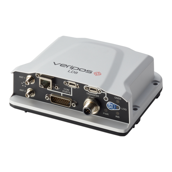
Hardware Overview 2. HARDWARE OVERVIEW This section describes the physical characteristics of the LD8, provides information on the different possible LED statuses and details the interface panel inputs. 2.1 OVERVIEW AND DESCRIPTION • The LD8 is a small, lightweight and low power system. -
Page 12: Log Led
Hardware Overview 2.2.3 LOG LED State Description LD8 is connected to a computer as a mounted device Green blink Logging to internal memory Green solid Internal logging stopped Green/Yellow Logging to internal memory with low memory available alternating blink Yellow solid... -
Page 13: Interface Panel Connections
ANT 2 connector. GNSS Heading Solution Direction 2.3.2 DATA CABLES The LD8 System is supplied with a multiport adapter that splits out into cabling for COM1, COM2, COM3 and 1 PPS signal from a 26-pin high-density connector: LD8 Operations Manual... -
Page 14: Ethernet And Webui Connection
LD8 for operation. Internet Explorer comes pre-loaded onto VERIPOS PCs when issued with the unit. The LD8 is shipped with a factory default IP address of 192.168.2.8. The connecting PC or laptop should be configured to use the same IP subnet. -
Page 15: Configuration And Operation
Configuration and Operation 4 CONFIGURATION AND OPERATION There are two ways in which the LD8 can be configured; via the WebUI or by using a licensed version of the VERIPOS Quantum software. It is recommended to use Quantum (see the Quantum User Manual) if available. -
Page 16: Command Sending Via Webui Terminal
4.1.2 SAVING CHANGES Whilst configuring the LD8 via the WebUI terminal, any configuration changes made will not get automatically saved. Although any configuration changes made may appear to immediately work, without use of a save command these changes will be lost in the event of a power cycle. -
Page 17: L-Band Configuration
L-band tracking in order to make use of VERIPOS services. 4.2.1 SELECTING AUTO BEAM Auto Beam is the recommended way to manage L-band beam choices. When in this mode the LD8 will track up to three beams simultaneously, with tracking determined based on available L-band satellites and elevation. -
Page 18: Entering A Custom Beam Frequency
4.2.3 ENTERING A CUSTOM BEAM FREQUENCY A custom L-band beam name and frequency (in Hz) can be manually entered, however this should be used only under the instruction of VERIPOS support. The format for assigning a user L-band beam is as follows: ASSIGNLBANDBEAM MANUAL BEAMNAME FREQUENCY 1200 4.2.4 TRACKED L-BAND BEAM AND SIGNAL STRENGTH STATUS... -
Page 19: Activation And Deactivation Of Veripos Services
Configuration and Operation 4.3 ACTIVATION AND DEACTIVATION OF VERIPOS SERVICES To activate or deactivate VERIPOS services, firstly ensure that the LD8 is switched on and tracking a L-band beam with a healthy signal level (>36.5 dB). Tracking of a L-band beam is required as activation and deactivation requests are sent via the beam. -
Page 20: Calculation Configuration
Some VERIPOS service codes include both the Apex and Ultra solutions. The LD8 can only compute one solution at a time, which can be specified by using the PPPSOURCE command. Where only one of the PPP services is enabled it is still required to match the selection to the activated service. -
Page 21: Ethernet Configuration
255.0","",1,"0.0.0.0"*d9d1437c 4.5.2 SETTING A STATIC IP The LD8 is preconfigured with a static IP of 192.168.2.8, however this IP address can be changed to a different static IP address. The command to change to a static IP follows the structure of: IPCONFIG [interface_name] [address_mode] [IP_address] [netmask] [gateway] IPCONFIG ETHA STATIC 192.168.2.8 255.255.255.0 192.168.2.1... -
Page 22: Output Configuration
LOG COM1 GPGGA ONTIME 1 LD8 receivers are capable of outputting messages at rates up to 20Hz. The last value as part of the LOG message is the output rate field. See below table for the output rates and the command variables:... -
Page 23: Gga Precision Selection
SERIALCONFIG COM1 9600 N 8 1 N OFF 4.6.6 PPS The LD8 allows for the PPS polarity to be configured and set to an increase in pulse from 0v (POSITIVE) or a decrease in pulse to 0v (NEGATIVE). The pulse has a width of 2000 microseconds. -
Page 24: Input Configuration
INTERFACEMODE COM1 VERIPOS_RTCM NOVATEL ON 4.7.2 INPUTTING RTK CORRECTIONS The LD8 is capable of utilising corrections from a source of RTK correction data. For the corrections to be accepted by the receiver they must be either RTCM v2, RTCM v3 or CMR format. -
Page 25: Rolling Log
4.8 ROLLING LOG 4.8.1 ACCESSING ROLLING LOG The LD8 is preconfigured to utilise a rolling data log. This data can be used to conduct various types of analysis or for troubleshooting purposes by VERIPOS. From this data, RINEX observation logs can be generated, if required. -
Page 26: Reference Information
LOG LBANDTRACKSTAT Check tracked L-band beam/s and signal strength/s LOG VERIPOSINFO Check unit ID and activation service code LOG VERIPOSSTATUSA Check present activation status of LD8 Configure number of Latitude decimal places in GGA NMEAFORMAT GGA_LATITUDE 10.5 message Configure number of Longitude decimal places in GGA NMEAFORMAT GGA_LONGITUDE 11.5... -
Page 27: Ld8 Output Sentences
The NMEA talker identifier serves to define the nature of the data being transmitted. The talker is the first 2 characters after the $ sign within the NMEA sentence. As the LD8 is capable of utilising more than only the GPS constellation, the talker has a set value for each constellation. -
Page 28: Gga Sentence
The number of decimal places in the GGA message Latitude and Longitude values is configurable, see section GGA Precision Selection for details. If making changes from 5 decimal places the sentence will no longer conform with NMEA v3.01. LD8 Operations Manual AB-V-MA-00635_RevA2... -
Page 29: Gst Sentence
Time and Date data hhmmss.ss UTC time in hours, minutes, seconds of the GPS position Day, 01 to 31 Month, 01 to 12 yyyy Year null Local zone hours (not available) null Local zone minutes (not available) Checksum LD8 Operations Manual AB-V-MA-00635_RevA2... -
Page 30: Gsa Sentence
Elevation, degrees (90° maximum) Azimuth, degrees true, 000 to 359 SNR (C/No) 00-99 dB-Hz, null when not tracking Checksum NOTE Fields dd, ee, fff and gg will be repeated a maximum of 4 times per sentence. LD8 Operations Manual AB-V-MA-00635_RevA2... -
Page 31: Gll Sentence
Nautical speed indicatior (N = Knots) ss.sss Speed over ground, kilometres/hour Speed indicator (K = km/hr) Positioning mode indicator (A = Autonomous, D = Differential, E = Estimated (Dead reckoning), M = Manual, N = Data not valid) Checksum LD8 Operations Manual AB-V-MA-00635_RevA2... -
Page 32: Grs Sentences
4 (BD) Signal Channel All Signals B2-a B2-b B2 a+b Ranging Signal ID GNSS Constellation: QZSS GNSS System ID 5 (GQ) Signal Channel All Signals L1 C/A L1C (D) L1C (P) L2C-M L2C-L Ranging Signal ID LD8 Operations Manual AB-V-MA-00635_RevA2... -
Page 33: Rmc Sentences
The NMEA HDT sentence provides heading information derived from the receiver. HDT SENTENCE STRUCTURE & EXAMPLE $GNHDT, dd.dddd, T hh $GNHDT, 75.5664, T *36 HDT SENTENCE DEFINED Heading (true) message dd.dddd Heading in degrees Degrees True Checksum LD8 Operations Manual AB-V-MA-00635_RevA2... -
Page 34: Veripos Ukooa Sentences
Reference Information 5.2.12 VERIPOS UKOOA SENTENCES The VERIPOS UKOOA sentence is compliant with OGP 373-19 and IMCA S015 (July 2011). For further information relating to these standards please visit https://www.iogp.org and https://www.imca-int.com. VERIPOS UKOOA SENTENCE STRUCTURE & EXAMPLE [ 240 7300 VERI 1 2067 295238.0 +0.1 +8.0 057 12.08207N 002 11.53776W 63.997 +50.40 1.151 0.564 1.004 7 0.025 0.054 0.14 0.001 0.000 0.000 0.003 0.06 0.05 6.5 P 15{ 20 27 13 30 26 8 21 16 7 10... - Page 35 Number of Reference Variable Stations used for this Fix (00 – 99) Ids of the Reference Variable Stations used in the Station ID numbers are space separated End of Character Close string Carriage Return Line Feed LD8 Operations Manual AB-V-MA-00635_RevA2...
-
Page 36: Contact Information
Contact Information 6 CONTACT INFORMATION All initial contacts regarding technical or support issues should be initially addressed to the VERIPOS Helpdesk. Where appropriate the Helpdesk will refer issues to the regional operations and engineering teams. 6.1 VERIPOS HELPDESK DETAILS VERIPOS Online Support System (VOSS) http://help.veripos.com... -
Page 37: Appendix
Appendix APPENDIX L-BAND COVERAGE MAP LD8 Operations Manual AB-V-MA-00635_RevA2...
Need help?
Do you have a question about the LD8 and is the answer not in the manual?
Questions and answers