Sony MVS-8000X System User Manual
Multi format switcher system
Hide thumbs
Also See for MVS-8000X System:
- User manual (1310 pages) ,
- Installation manual (58 pages) ,
- Operation manual (26 pages)

Related Manuals for Sony MVS-8000X System


Summary of Contents for Sony MVS-8000X System
- Page 1 MVS-8000X System (With CCP-9000 Series Center Control Panel) User’s Guide Multi Format Switcher System [English] Volume 1 1st Edition (Revised 1) Software Version 10.00 and Later...
- Page 2 NOTICE TO USERS © 2010 Sony Corporation. All rights reserved. This manual or the software described herein, in whole or in part, may not be reproduced, translated or reduced to any machine readable form without prior written approval from Sony Corporation.
- Page 3 Functions Newly Supported in Version 10.00 The functions newly supported in the MVS-8000X system version 10.00 are as follows. Functions relating to operability Classification Functions supported Menu No. See page Vol.1 Vol.2 Vol.3 Control panel Assignment of keys 1 to 8 to region 7321.17...
- Page 4 Functions relating to setup Classification Functions supported Menu No. See page Vol.1 Vol.2 Vol.3 System Support for SD format 7313 – Support for 1080PsF/24, 1080PsF/ 7313 – – 25, and 1080PsF/29.97 formats Support for switcher Resume mode 7314 – – DME input/output signal format 7316.8 –...
-
Page 5: Table Of Contents
Table of Contents Volume 1 Chapter 1 MVS-8000X Functions Introduction ....................26 Features of the MVS-8000X Multi Format Switcher System....28 Basic Video Processing.................30 Transitions .....................30 Keys.......................34 Wipes.....................35 DME Wipes ...................36 Frame Memory ..................36 Color Backgrounds................36 Copy and Swap..................37 Video Process ..................37 Color Corrector..................37 Side Flags ....................38 Multi Program 2 ..................38... - Page 6 Keyframe Control Block ...............57 Numeric Keypad Control Block............60 Auxiliary Bus Control Block..............63 Menu Control Block ................64 “Memory Stick”/USB Connections Block ..........65 Key Control Block (MKS-8035 Key Control Module, Option) ...67 Device Control Block (MKS-8031TB Trackball Module, Option) ..71 Device Control Block (MKS-8036A Search Dial Module, Option) ..74 Utility/Shotbox Control Block (MKS-8033 Utility/Shotbox Module, Option) ..................78 Downstream Key Control Block (MKS-8032 DSK Fader Module,...
- Page 7 Color Matte Settings...................131 Executing a Transition ................134 Transition Indicator Function ..............134 Setting the Transition Rate ..............135 Pattern Limit..................137 Executing an Auto Transition..............140 Executing a Transition With the Fader Lever (Manual Transition) ..142 Combinations of Auto and Manual Transitions ........142 Non-Sync State..................142 Fader Lever Operation in Bus Fixed Mode.........143 Transition Preview ..................146 Independent Key Transitions ..............148...
- Page 8 Key Edge Modifications..............201 Masks....................205 Applying a DME Effect to a Key ............206 Other Key Setting Operations .............207 Resizer ......................210 Two-Dimensional Transformations of Keys ........210 Resizer Interpolation Settings .............214 Resizer Crop/Border Settings ..............215 Applying Resizer Effects..............218 Key Snapshots.....................224 Key Snapshot Operations ..............224 Chapter 5 Wipes Overview......................228 Types of Wipe Pattern .................228...
- Page 9 Basic Procedure for Independent Key Transition DME Wipe Settings ....................284 Setting Independent Key Transition DME Wipe Modifiers....285 Resizer DME Wipe Setting ................288 DME Wipe Snapshots ................290 DME Snapshot Operations With the Menus ........290 Creating User Programmable DME Patterns .........291 User Programmable DME Transition Mode ........291 Chapter 7 Frame Memory Overview......................298 Still Image Operations ................301...
- Page 10 Managing Images Using a DDR/VTR............342 Using a DDR/VTR for High-speed Backup and Restoring....342 Extracting Images from Video Tape ...........344 Chapter 8 Color Backgrounds, Copy and Swap, and Other Settings Color Background ..................348 Color Background Settings Menu ............348 Basic Color Background Setting Operations........348 Copy and Swap ...................352 Copy and Swap Operations ...............356 Copy and Swap Menu Operations............356...
- Page 11 Spot Color Adjustment ................384 Output Video Processing Operations ..........386 YUV Clip Operations ................387 RGB Clip Operations ................388 Chapter 10 Special Functions Side Flags.....................392 Overview .....................392 Side Flag Settings ................392 Wipe Action on Images With Side Flags ..........394 DME Wipe Action for an Image With Side Flags ......395 Multi Program 2 ..................397 Overview .....................397 Sequence of Operations in Multi Program 2 ........398...
- Page 12 Color Bkgd Menu ................440 AUX Menu ..................440 CCR Menu...................441 Copy/Swap Menu ................442 Misc Menu...................442 Status Menu ..................443 DME Menu..................444 Global Effect Menu ................445 Device Menu ..................445 Macro Menu ..................446 Key Frame Menu.................447 Effect Menu ..................448 Snapshot Menu ..................449 Shotbox Menu ..................450 File Menu ....................451 Engineering Setup Menu ..............452 Diagnostic Menu .................457...
- Page 13 Special Effects ..................492 Operations Common to All DME Special Effects ......506 Border Settings ..................507 Crop Settings ..................509 Beveled Edge Settings.................511 Key Border Settings ................513 Art Edge Settings.................514 Flex Shadow Settings ................522 Wipe Crop Settings ................529 Color Mix Settings ................533 Defocus Settings..................535 Blur Settings ..................537 Multi Move Settings ................537 Sepia Settings ..................538...
- Page 14 Global Effect Operations ................625 Combiner Settings ................626 Brick Settings ..................633 Shadow Settings ..................637 Chapter 12 External Devices Control of External Devices...............640 Shared Functions for External Device Control ........641 Control of P-Bus Devices ................643 Creating and Editing the P-Bus Timeline..........643 P-Bus Trigger ..................646 Control of GPI Devices ................648 GPI Timeline Creation and Editing.............648 Control of VTRs, Extended VTRs, and Disk Recorders ......652...
- Page 15 Selecting the Region in Which Editing Applies........705 Setting the Edit Points .................707 Creating and Editing Keyframes ..............709 Creation ....................709 Insertion....................710 Modification ..................710 Deletion ....................714 Movement....................715 Copying ....................716 Pause....................716 Keyframe Loop (Repeated Execution of a Specified Range) .....717 Undoing an Edit Operation..............720 Duration Mode Setting ................720 Transition Mode Settings for User Programmable DME....721 Time Settings....................722...
- Page 16 Saving and Recalling Snapshots............751 Snapshot Operations in the Menus ............756 Selecting a Region or Reference Region in a Menu......756 Setting Snapshot Attributes ..............756 Snapshot Status Display ..............759 Setting Key Snapshot Attributes ............760 Creating and Saving a Master Snapshot..........761 Snapshot Register Editing ..............762 Displaying a List of Snapshot Registers for Editing ......762 Operations in the Misc >Snapshot Menu ..........763 Chapter 15 Utility/Shotbox...
- Page 17 Online Editing of Macro Events............801 Offline Editing of Macro Events ............807 Macro Attachment Assigning ..............813 Setting and Canceling a Macro Attachment........815 Displaying the Macro Attachment List ..........818 Executing a Macro by Macro Attachment...........819 Menu Macros ....................822 Recalling a Menu Macro Register and Executing a Menu Macro ..823 Menu Macro Creation and Editing ............827 Menu Macro Register Editing .............832 Macro Timeline...................834...
- Page 18 Renaming a Directory .................867 Deleting a Directory ................867 Copying Files Between Different Unit IDs ..........868 Saving Files Recalled by Autoload ............870 Appendix (Volume 2) SpotLighting....................874 Texture Patterns...................874 Shape Patterns ..................875 Functional Differences With Models of DME..........876 Macro File Editing Rules ................878 Macro File Syntax ................878 Syntax of Event and Continue Statements ..........879 File Name ....................880...
- Page 19 Setting the Screen Aspect Ratio (Format Menu)........913 Selecting the State After Powering On (Start Up Menu)......914 Saving and Recalling Setup Data ............915 Selecting the State at Start-up .............916 Saving User-Defined Settings .............917 Setting Automatic Loading of Register Data at Power On (Autoload Function) ..................917 Reset and Initialization (Initialize Menu)..........918 Installation and Device Setup (Install/Unit Config Menu) .....919...
- Page 20 Assigning Keys to the Independent Key Transition Control Block (Simple Type) ................955 Assigning Functions to Key Control Block Buttons ......957 Assigning Preview Output to Preview Selection Buttons ....958 Assigning Functions to the Device Control Block ......960 Inhibiting Utility 2 Bus and Key Operations........962 Inhibiting DME Channel Selection Operations........963 Assigning Functions to the Menu Control Block Top Menu and User Preference Buttons ..............963...
- Page 21 Settings for the Wipe Snapshot Menu ..........1007 Setting the Button Operation Mode...........1008 Setting the Operation Mode of the [ALL] Button in the Transition Control Block .................1010 Setting Trackball, Joystick, Search Dial, and Double-Click Sensitivity ....................1010 Specifying Main Split Fader..............1011 Setting the Macro Execution Mode...........1011 Screen Saver and Other Settings (Maintenance Menu)......1014 Screen Saver Settings ................1014 Adjusting the Brightness ..............1014...
- Page 22 Settings Relating to Keys, Wipes, Frame Memory and Color Correction (Key/Wipe/FM/CCR Menu) ............1046 Switching Video Process Memory On or Off ........1047 Settings for the Show Key Function..........1047 Settings for Key Auto Drop Function ..........1047 Automatically Naming and Saving to Frame Memory .....1048 Selecting the Bank to Make the Settings...........1048 Settings Relating to Function Links (Link Menu).........1051 Setting a Cross-Point Button Link.............1051...
- Page 23 Making DCU GPI Input Settings ............1079 Parallel Output Settings (Output Config Menu) ........1083 Assigning a GPI Output Port.............1083 Releasing the Assignment of a GPI Output Port .......1084 GPI Output Setting (GPI Output Assign Menu) ........1085 Making DCU GPI Output Settings............1085 Serial Port Settings (Serial Port Assign Menu) ........1088 Making Serial Port Settings...............1088 Making Detailed Settings on the External Device Connected to the Serial...
- Page 24 Setting Status of the MKS-8080/8082 in Simple Connection....1119 Chapter 25 DIAGNOSIS Checking the Communications Status............1122 Communications Status Display ............1122 Appendix (Volume 3) Data Saved by [Setup Define] and [Initial Status Define].....1126 Data Saved by [Setup Define] ............1126 Data Saved by [Initial Status Define]..........1131 Error Messages ..................1134 Error Messages Displayed in the Error Status/Error Log Menu ..1134 Error Messages Appearing in a Message Box........1138...
-
Page 25: Chapter 1 Mvs-8000X Functions
Chapter 1 MVS-8000X Functions... -
Page 26: Introduction
Introduction This manual is the User's Guide for the MVS-8000X Multi Format Switcher system. This manual describes principally the operation of the system using the CCP- 9000A of center control panels. The User's Guide for this system comprises three volumes. For the contents of each volume, see the section “Organization of This User’s Guide”... -
Page 27: Related Manuals
System configuration and features Term for system A system in which the center control panel 2M/E system has two M/E banks A system in which the center control panel 1M/E system has one M/E bank Related manuals MVS-8000X-C Switcher Processor Pack •... -
Page 28: Features Of The Mvs-8000X Multi Format Switcher System
DME functionality. Powerful external device interfaces By connecting to a Sony routing switcher or similar, a large system can be built. From the control panel, it is also possible to operate other equipment, including VTRs and disk recorders. - Page 29 Powerful frame memory functions The frame memory can hold approximately 1000 frames in an HDTV system (approximately 2000 frames in 720P/59.94 format), or approximately 5000 frames in an SDTV system in 480i/59.94 format, or approximately 4000 frames in 576i/50 format, and allows eight frames (four frames in 1080P format) to be recalled simultaneously.
-
Page 30: Basic Video Processing
Basic Video Processing This section introduces basic functions used for video processing on the switcher. Transitions In the M/E banks and PGM/PST bank, the switch from the current video stream (appearing on the corresponding program monitor) to a new video stream is referred to as a transition. - Page 31 Inserting and deleting a key You can insert one or more of the eight keys (downstream keys on the PGM/ PST bank). If you select a key which is already inserted, the transition will delete the key. A simultaneous combination of deleting and inserting keys is also possible. Key 1 Insert Delete...
- Page 32 Simultaneously changing the background and keys You can change any of the eight keys (downstream keys on the PGM/PST bank) and the background at the same time. Key 1 Transition Key 2 Changing the background and key 2 simultaneously Key 1 Transition Key 2 Key 4...
- Page 33 There are two modes for carrying out a transition: auto transitions are carried out by a button operation, and manual transitions are carried out using the fader lever. It is also possible to combine these two modes. Independent Key Transitions In addition to common transitions, it is possible to carry out independent transitions on the keyers of the M/E banks and PGM/PST bank.
-
Page 34: Keys
Effect of use with an independent key transition The key is inserted with an independent key transition as the background changes with a common transition, providing the following result. Different wipe patterns are applied to Independent key Transition type: the background and key transitions. transition type: wipe wipe... -
Page 35: Wipes
Masks A mask allows a part of the image to be replaced by the background or a key. To prevent unwanted holes in the background, or if a key is not the desired shape, you can correct this with a mask. Resizer This function allows you to apply effects, similar to a DME, such as zoom, movement, or aspect ratio change to a part of a created key. -
Page 36: Dme Wipes
DME Wipes A DME wipe is a wipe transition that uses a DME effect to change from one video image to the next. There are two types of DME wipe: those which can be selected for a normal transition, and those which can be selected for an independent key transition. The patterns that can be used for a DME wipe are as follows. -
Page 37: Copy And Swap
Copy and Swap This function can be used to copy and swap the settings among the M/E-1 to M/E-3, and PGM/PST banks or between keyers. The following settings can be copied or swapped. • Overall settings for the M/E and PGM/PST banks •... -
Page 38: Side Flags
Side Flags The term “side flags” refers to the areas to left and right of an image with aspect ratio 4:3 embedded within a 16:9 frame, when these areas are filled with a separate image selected from the utility 1 bus. Image to fill the side flag Input source with aspect ratio areas (selected from utility 1... - Page 39 Key 3 Background A (signal from utility 2 bus) Background A Key 1 Background B (signal from utility 3 bus) Background B Program output for “Main” Program output for “Sub” For details, see “Multi Program 2” (page 397). Basic Video Processing...
-
Page 40: Creation Of Special Effects And Management Of Data And Operations
Creation of Special Effects and Management of Data and Operations This section introduces functions used for creation of special effects, control of external devices or switcher operations, and data management. Digital Multi Effects (DME) When used with the switcher, DME allows you to add three-dimensional effects such as image movement, rotation, magnification and shrinking, as well as a wide variety of special effects. -
Page 41: External Devices
• Disk recorder (Sony disk 9-pin protocol and video disk communications protocol) • Extended VTR (Abekas A53 protocol) For details on the devices that can be connected, consult your Sony representative. You can control an external device by previously registering timeline keyframes. -
Page 42: Snapshots
The following figure shows three keyframes created with a wipe pattern (the circle) in different positions. This is interpolated to create the effect shown. Background A Interpolated images Background B Keyframe 1 Keyframe 2 Keyframe 3 Effect execution Example of keyframes and effect execution You can save the sequence of keyframes representing a single effect in a register. -
Page 43: Utility
These conditions are called “attributes” of the snapshot, and can be added when the snapshot is saved or recalled. For details, see Chapter 14 “Snapshots” (Volume 2). Utility The utility function refers to a function whereby you can assign an arbitrary action or a shortcut for frequently used menu to a particular button, then instantly recall the action or menu by pressing the button. -
Page 44: Files
Macro attachment Macro attachment is a function whereby a macro register is assigned to a control panel button or a particular position of a fader lever, linking the execution of the button function or a fader lever operation with a macro execution. -
Page 45: Setup
Setup Various settings are required, in order to operate the switcher, control panel, DME, external devices, and so on, connected together in a single system. This is referred to as “setup,” and you can carry out the setup operations from the Engineering Setup menu. - Page 46 Setup...
-
Page 47: Chapter 2 Menus And Control Panel
Chapter 2 Menus and Control Panel... -
Page 48: Names And Functions Of Parts Of The Control Panel
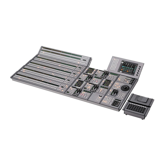
Names and Functions of Parts of the Control Panel Example Control Panel Configuration Device control block (joystick) (page 56) Auxiliary bus control block (page 63) Numeric keypad control block (page 60) “Memory Stick”/USB connections block (page 65) Menu control block (page 64) Keyframe control block (page 57) Key control block (page 67) Device control block... - Page 49 Device control block (joystick) (page 56) Auxiliary bus control block (page 63) Numeric keypad control block (page 60) “Memory Stick”/USB connections block (page 65) Menu control block (page 64) Keyframe control block (page 57) Key control block (page 67) Device control block (page 71) Utility/Shotbox control block (page 78)
-
Page 50: Cross-Point Control Block
Cross-Point Control Block In the cross-point control block, you can select the signals to be used in this M/E bank or PGM/PST bank. 2 Source name displays Key row 4 XPT HOLD button 5 SHIFT button 3 Key row delegation buttons Background B row Background A row 1 Cross-point buttons... -
Page 51: Transition Control Block
background video on this M/E bank or display, for each source separately. You can PGM/PST bank. set the source name display mode and Background B row: Press the desired background color in a Setup menu. button to select the signal as the c Key row delegation buttons background after the next transition on Use these buttons to assign buses to the key... - Page 52 9 PRIOR SET button 1 Next transition selection buttons 8 Key status display 2 Transition type selection buttons 0 Independent key/downstream key transition execution section 7 KF button 6 Pattern limit buttons 5 TRANS PVW button 3 Transition execution section 4 Wipe direction selection buttons a Next transition selection buttons In the PGM/PST bank, this inserts or...
- Page 53 priority after the next transition appears zero in the second half while the new in the key status display. video is maintained at 100%. ALL: Pressing this button turns on a PST (preset) COLOR MIX: In the first preselected set of the [BKGD], [KEY1] transition, the current video is replaced to [KEY8], and [KEY PRIOR] buttons.
- Page 54 f Pattern limit buttons transition of the set transition rate (duration). The transition starts PTN (pattern) LIMIT: Pressing this immediately, and the button lights button, turning it on, enables the amber. When the transition completes, pattern limit function. the button goes off. LIMIT SET: Use this button to set a CUT button: Pressing this button carries pattern limit when the [PTN LIMIT]...
- Page 55 or keys 5 to 8, but not for combinations of keys from different groups. For example, it is not possible to set a priority sequence of keys 1, 5, and 2. For details, see “Setting the Key Priority in the Transition Control Block” (page 122). The following controls are used as the independent key transition control block.
-
Page 56: Device Control Block (Joystick)
Device Control Block (Joystick) The joystick type device control block is used for three-dimensional transform operations using a DME. 1 Operating buttons 2 Joystick 3 MENU button a Operating buttons the [SHIFT] button enables the shifted The functions of these buttons are function of the button. -
Page 57: Menu Button
b Joystick When the effect run control mode is When the three-dimensional transform enabled operation mode is enabled By moving the joystick sideways, you can By moving this, you can carry out run the keyframe effect, independent of the operations in the x-, y-, and z-axes. STOP NEXT KF, EFF LOOP, and similar When the following buttons are held down, settings in the keyframe control block. - Page 58 8 Effect execution direction selection buttons 0 EFF LOOP button 9 STOP NEXT KF button 1 EDIT ENBL button 4 Duration setting buttons 5 KF LOOP button 6 PAUSE button qa RUN CTRL button 3 Editing buttons 7 Effect execution section 2 Edit point specification buttons a EDIT ENBL (edit enable) button To move the edit point to the specified...
- Page 59 During macro editing, pressing this the edit point is between two button moves the edit point to the event keyframes, the immediately preceding immediately before the current event. keyframe is deleted. During macro NEXT KF (next keyframe): When this editing, pressing this button deletes the button is pressed, the edit point moves selected event.
-
Page 60: Numeric Keypad Control Block
h Effect execution direction selection mode is constant duration mode, and when off, variable duration mode. buttons REV (reverse): When this button is off, e KF LOOP (keyframe loop) button effect execution runs from the first Press this button, turning it on, to execute keyframe to the last keyframe. - Page 61 1 Mode selection buttons 5 Display 4 Numeric keypad 3 Function selection buttons 2 Region selection buttons a Mode selection buttons You can select more than one region at the EFF (effect): Press to save or recall an same time. effect.
- Page 62 DME1 to DME8: Select a DME channel. applies the effect dissolve attribute to a P-Bus: Select the P-Bus region. snapshot. GPI: Select the GPI region. CLR/AUTO TRANS (clear/auto RTR: Select the router region. transition): Clear an input value, DEV1 to DEV12: Select the Device 1 to returning to the previous state.
-
Page 63: Auxiliary Bus Control Block
Auxiliary Bus Control Block 4 SHIFT button 1 AUX delegation buttons 2 Bank selection buttons 3 KEY button b Bank selection buttons a AUX delegation buttons Press one of these buttons, turning it on, to These select the bank for which the AUX select the bus to assign to the key row of the delegation buttons are enabled. -
Page 64: Menu Control Block
Menu Control Block 1 Top menu selection buttons 2 Menu display 4 User preference buttons 3 Knobs a Top menu selection buttons c Knobs These select the menu appearing in the These adjust the parameter values menu display. appearing in the menu. It is also possible to change the assignment d User preference buttons of these buttons in setup. -
Page 65: Memory Stick"/Usb Connections Block
For details on the devices that can be • A “MagicGate Memory Stick” can also connected, consult your Sony be used, but this system does not support representative. the MagicGate function. - Page 66 Adaptor” (MSAC-M2 or equivalent). If you insert a “Memory Stick Duo” without using the adaptor, there is the possibility that the stick cannot be removed, resulting in a serious accident. Handling “Memory Sticks” When using “Memory Sticks,” pay attention to the following points. •...
-
Page 67: Key Control Block (Mks-8035 Key Control Module, Option)
Key Control Block (MKS-8035 Key Control Module, Option) Each of the M/E and PGM/PST banks desired keyer. In this control block, you can includes eight keyers (for keys 1 to 8), and adjust and modify keys. you can delegate this control block to any 3 Key fill/key source selection buttons 2 Key type selection buttons 1 Delegation buttons... - Page 68 M/E delegation: Press one of the [M/E 1] PTN: key wipe pattern key to [M/E 4], and [P/P] buttons to select For details, see “Key Types” (page 156). the bank (the M/E bank or PGM/PST bank) to which the key control block is c Key fill/key source selection buttons delegated.
- Page 69 BDR (border): Apply a border of a and subsequent parameters are assigned to uniform thickness to the whole key. the knobs, allowing them to be adjusted. DROP BDR (drop border): Apply a f SHOW KEY button border to two sides of the key (for While this button is held down, a key example, below and to the right, or processed key source signal is output from...
- Page 70 j ON AIR indicators source signals to which a DME effect is These light red when the corresponding applied are assigned; otherwise the key DME channels are included in the final fill and key source are assigned. program output. l OVERRIDE button k Output destination specification To select a DME channel already allocated buttons...
-
Page 71: Device Control Block (Mks-8031Tb Trackball Module, Option)
Device Control Block (MKS-8031TB Trackball Module, Option) The device control block is used for three- for VTR/disk recorder or frame memory dimensional transform operations using a clip operations. DME, for wipe pattern position setting, and 5 MENU button 1 Region selection buttons 3 Trackball 2 Operating buttons 4 Z-ring... -
Page 72: Operation Buttons
Press a button, turning it on, to select a The functions of the operation buttons, DME channel. You can select multiple trackball, and Z-ring vary with the buttons simultaneously. operation mode as follows. The number of valid buttons depends on the number of DME processor [FX CTRL] button: Leave this button off channels installed. - Page 73 this enables the trackball to move the ROT (RSZE: resizer): Press this button, pattern in the x-axis and y-axis turning it on, to enable the resizer. directions, and the Z-ring to adjust the CLR WORK BUFR (clear work buffer): size of the pattern. Pressing this button once returns the X, Y: These restrict the axes affected by the two-dimensional transformation...
-
Page 74: Device Control Block (Mks-8036A Search Dial Module, Option)
d Z-ring When the [LOC SIZE] or [LOC XYZ] When the positioner operation mode is button is held down, the Z-ring operation is enabled switched to a finer control. (fine mode) When the [USER] button is selected, by turning the ring you can adjust the size of When the VTR/disk recorder/frame the pattern. - Page 75 4 DELAY button 7 TIMELINE button 2 Device selection buttons 8 STOP button 6 External device 1 Timecode display operation buttons 5 Editing 9 Search dial buttons 3 SBOX buttons a Timecode display When the [TIMELINE] button is off: This shows the current time (CURRENT) Displays the Cueup &...
- Page 76 button, the second button will be the START TC: When pressed, this button reference device and light green. flashes amber, and sounds a beep, DEV: Assign external devices DEV1 to setting the timecode at that time as the DEV12. device start point (on the timeline when FM CLIP: Assign frame memory clips the [TIMELINE] button is On, and FM1 to FM8.
- Page 77 This button cannot be used for frame and the image from the selected device memory clip operations. is recorded. CUE: When pressed, this button flashes This button cannot be used for frame amber together with the [ALL STOP] memory clip operations. button, and the device selected with the f External device operation buttons device selection button is cued up to the...
-
Page 78: Utility/Shotbox Control Block (Mks-8033 Utility/Shotbox Module, Option)
Utility/Shotbox Control Block (MKS-8033 Utility/ Shotbox Module, Option) 1 Bank selection buttons 2 Memory recall buttons a Bank selection buttons lights orange, and the assigned register Press any of the [BANK1] to [BANK4] name appears. (If the register is empty, the buttons to select a bank of 24 memory recall button goes off.) In the case of a shotbox function, pressing the button executes the... -
Page 79: Downstream Key Control Block (Mks-8032 Dsk Fader Module, Option)
Downstream Key Control Block (MKS-8032 DSK Fader Module, Option) 1 Key delegation buttons 5 Key source name display/key snapshot buttons 4 Key snapshot setting buttons 2 Independent key transition type selection buttons 3 Independent key transition execution section a Key delegation buttons WIPE: Carry out a wipe with the key Press one of the [DSK1] to [DSK4] buttons selected with the key delegation... - Page 80 c Independent key transition execution section DSK1 (downstream key 1) ON to DSK4 ON buttons: Press these to instantaneously cut the downstream keys 1, 2, 3, and 4 in or, when the downstream keys are already inserted, cut them out. When the key corresponding to the button appears in the final program output, the button lights red, and otherwise lights amber.
-
Page 81: Basic Menu Operations
Basic Menu Operations To display the top menu Menu Organization In the same way as for the top menu selection buttons in the menu control block, Operations on the MVS switcher system press each button to display the particular make frequent use of menu operations. top menu in the menu display. - Page 82 Depending on the button, this may particular menu, or enter the menu display a fixed page or the page selected number with the numeric keypad, and last time you accessed the menu. press the Enter button. • Press the menu page selection button at For details of the VF buttons and HF the top left of the menu display.
- Page 83 Buttons Menus Function Engineering Setup Setup functions Chapter 18 to Chapter 24 SETUP (Volume 3) DIAG Diagnosis Status information display Appendix (Volume 3) Menus accessed by pressing a button twice For relevant buttons other than the top buttons of each control block, together with menu selection buttons, pressing twice in the menus they recall.
- Page 84 Transition control block Buttons Menus KEY1 (DSK1) • M/E-1 >Key1 >XX page 163 • PGM/PST >DSK1 >XX KEY2 (DSK2) • M/E-1 >Key2 >XX • PGM/PST >DSK2 >XX KEY3 (DSK3) • M/E-1 >Key3 >XX • PGM/PST >DSK3 >XX KEY4 (DSK4) • M/E-1 >Key4 >XX •...
- Page 85 Key control block Buttons Menus KEY1 • M/E-1 >Key1 >XX page 163 • PGM/PST >DSK1 >XX KEY2 • M/E-1 > Key2 > XX • PGM/PST >DSK2 >XX KEY3 • M/E-1 >Key3 >XX • PGM/PST >DSK3 >XX KEY4 • M/E-1 >Key4 >XX •...
- Page 86 a) The menu recalled depends on which of the M/E-1 bank and PGM/PST bank the numeric control block is delegated to. b) When other than [MASTR] is selected with the region selection buttons. c) When [MASTR] is selected with the region selection buttons. d) When the [SNAPSHOT] button or [EFF] button is set to On, or lit green.
-
Page 87: Displaying A Menu
Device control block (trackball) Buttons Menus DME1 to DME8 DME >XX Chapter 11 (Volume 2) DEV1 to DEV12 assigned • Device >DDR/VTR >Cueup & Play Chapter 12 buttons • Device >DDR/VTR >Timeline (Volume 2) FM1CLIP to FM8CLIP Frame Memory >Clip >Recall –... -
Page 88: Interpreting The Menu Screen
5 Status area qs b (previous) button and B (next) button 6 Function button area 2 Menu page number button 7 Parameter group button 1 Menu title 0 Keyframe status button qa Default recall button 4 HF buttons 8 Knob parameter 3 VF buttons buttons... - Page 89 d HF buttons Switching the VF buttons between the Key1 to Key4 and Key5 to Key8 button These indicate the items within the menu. displays Depending on the selected item, the menu Switch the displays with the [KEY1-4] and indications change. [KEY5-8] menu title buttons.
-
Page 90: Menu Operations
parameters, which can then be controlled • Function grouping: the functions within an HF menu under the VF button by the knobs. • Knob parameters (parameters currently h Knob parameter buttons controlled by the knobs) These show the parameters currently l b (previous) button and B (next) controlled by the knobs and their values. - Page 91 Lit pale blue: The function is enabled, and Setting parameters the parameters can currently be adjusted with the knobs. Lit orange: The function is enabled. Lit purple: Execution button. Pressing the mark button immediately executes the function. (Example: [Auto Start] This marking on a function button indicates button in the Chroma Adjust menu) that there are parameters which can be...
- Page 92 This returns the settings within the This returns the knob parameter value function grouping to the default state, to the default state, and the [Default and the [Default Recall] button goes Recall] button goes off. off. Notes Notes • In the following table, “Menus allowing a return to default settings,”...
- Page 93 Top menu selection VF number Menu number Menu name button name (HF number) M/E2 1210-series/1610-series Key1/Key5 1220-series/1620-series Key2/Key6 1230-series/1630-series Key3/Key7 1240-series/1640-series Key4/Key8 1250-series Wipe 1260-series DME Wipe 1270-series Misc M/E3 1310-series/1710-series Key1/Key5 1320-series/1720-series Key2/Key6 1330-series/1730-series Key3/Key7 1340-series/1740-series Key4/Key8 1350-series Wipe 1360-series DME Wipe 1370-series...
- Page 94 Top menu selection VF number Menu number Menu name button name (HF number) FRAME MEM 2510-series Still 2520-series Clip 2530-series Reposition/Lock 2540-series File 2550-series Folder 2311 Aux Bus 4110-series Edge 4120-series Video Modify 4131 Freeze 4141 Non-Linear 4150-series Light/Trail 4160-series Input/Output 4170-series Enhanced Video...
- Page 95 Knob parameters to which default recall does not apply Menu name Button name Knob Parameter Menu number 1113 Main Mask [Pattern] Pattern [Multi] Invert Type 1116 Transition [Wipe] in <ON Transition Type> Transition group Rate Pattern [Wipe] in <OFF Transition Type> Transition group Rate...
- Page 96 Knob parameters subject to restriction on default recall Menu number Menu name Button name Knob Parameter 1111.1 Type >CRK Adjust [Sample Mark] in the <Auto> group Position H Position V 1112.1 Edge >Matte [Position] Adjust 1113 Main Mask [Position] 1116.1 Transition >Wipe [Position] Adjust...
- Page 97 Numeric keypad window “Setting the Signal Format (Format Menu)” in Chapter 18 (Volume 3)) as follows: 00:00:00:00 to 23:59:59:nn, 1 Item display where nn = (number of frames per 2 Max./min. value indication second) – 1. 3 Input value f – (minus) button This toggles the sign of the entered value.
- Page 98 Keyboard window space, \, /, :, ;, , (comma), . (dot), <, >, Notes *, ?, ", | Except when changing source names, the following characters cannot be used. 4 BS button 1 Item display 2 Input string 3 Close button qd Line feed button 7 Space button...
-
Page 99: Clear Button
j Left button MS-DOS does not distinguish case in filenames, and therefore you are This moves the cursor one character to the recommended to enter filenames in capital left in the input string. letters. k Right button f Shift button This moves the cursor one character to the This selects the characters on the shift side right in the input string. - Page 100 a Top menu selection buttons Shutting down the menus These are the same as the top menu selection buttons in the menu control block. In the menu screen, press the menu Pressing one of these buttons closes the top page number button to open the top menu window and displays the selected menu window.
- Page 101 1Color palette buttons 2Operation buttons 3Color display 4Numeric keypad a Color palette buttons color palette button is set to the default Press one of these to enter the color. corresponding color in the display. c Color display By default the following settings are This shows the setting color, and the available.
-
Page 102: Switching Between The Main Menu Site And Subsidiary Menu Site
Switching Between the Main Menu Site and Subsidiary Menu Site For menu transitions, you can store two separate versions in the main and subsidiary menu sites. By switching sites, and pressing the b button and the B button you can trace the In the [Group Select] box, select the history in each menu. - Page 103 Press [Yes]. This deletes the settings. To register a menu on a button You can register 15 buttons in one group. In the Home >Favorites >Shortcut menu, press [Button Edit]. With the cursor, select the group name (in this case a blank button) for the operation.
- Page 104 To change the button color, press To execute a menu macro with a button [Color Set]. See “Recalling a Menu Macro Register and Button color samples appear. Executing a Menu Macro” in Chapter 16 (Volume 2). Press the desired color. This completes the assignment of the menu to the button.
-
Page 105: Chapter 3 Signal Selection And Transitions
Chapter 3 Signal Selection and Transitions... -
Page 106: Video Processing Flow
Video Processing Flow The switch from the current video stream (appearing on the corresponding program monitor) to a new video stream is referred to as a transition. The following illustration shows the flow of operations for carrying out a transition on an M/E bank or the PGM/PST bank. Video Processing Flow... - Page 107 Select current background video (page 108) Select next transition (page 116) Background Keys 1 to 8 Select new background video (page 108) Make key settings (page 155) Select transition type (page 116) DME wipe Super Preset color Wipe Make wipe settings (page 229) Make DME wipe settings (page 273)
-
Page 108: Signal Selection
Signal Selection You carry out signal selection with the cross-point buttons in the cross-point control block of the M/E bank or PGM/PST bank, and the buttons in the auxiliary bus control block. Source name displays Key row XPT HOLD button Key delegation buttons SHIFT button Background B row... -
Page 109: Bus Selection
Bus Selection The key row is shared by multiple buses. To assign a bus to the cross-point buttons in the auxiliary bus control block, press one of the AUX delegation buttons to select the bus. The following table illustrates the correspondence between buses and cross- point button rows, and the delegation operations. -
Page 110: Signal Assignment And Selection
Bank Bus name Cross-point Delegation operation button row Auxiliary AUX1 to AUX48 buses The key row of Turn on the appropriate bus control the bank selected buttons in accordance with Frame memory source block with the bank the signal assignment made 1 and frame memory selection buttons in the Setup menu. - Page 111 Each button has assigned to it a video signal and a key signal, forming a pair. You can set these video and key combinations in a Setup menu. For details of Setup menu operations, see “Cross-Point Settings (Xpt Assign Menu)” in Chapter 19 (Volume 3). Cross-point button control block button numbers On the M/E and PGM/PST banks, each cross-point button has two button numbers, and you use the [SHIFT] button to switch between these numbers.
- Page 112 Button numbers when all 12 buttons are used as cross-point buttons. SHIFT button When the SHIFT button is off: When the SHIFT button is on: Button numbers when the rightmost buttons (12th buttons) are used as SHIFT buttons. SHIFT button SHIFT buttons When the SHIFT button is off: When the SHIFT button is on:...
- Page 113 Inhibiting cross-point button operations For each cross-point button, you can temporarily inhibit operations. Notes This setting is cleared when you reset the control panel. Assigning a button to the function of disabling cross-point button operation You can assign the button to be used for the operation to a user preference button, in setup.
-
Page 114: Signal Name Display
For details of the setting, see “Cross-Point Settings (Xpt Assign menu)” in Chapter 19 (Volume 3). Notes • For details of audio mixers that can be connected, contact your Sony service or sales representative. • When the signal is switched with a snapshot, keyframe, and so on, the audio mixer is not linked. - Page 115 Significance of colors of lit cross-point buttons Color State Significance Amber Low tally Does not appear in final output video High tally Appears in final output video Signal Selection...
-
Page 116: Transitions
Transitions Selecting the Next Transition To execute a transition, it is first necessary to decide how the image will be changed as a result of the transition. This selection is carried out using the next transition selection buttons (see page 52) in the transition control block of each M/E or PGM/PST bank. - Page 117 Notes This transition type is not available for an independent key transition. Super mix In this dissolve, the current video is maintained at 100% output for the first half of the transition as the new video is mixed while increasing progressively to 100%, then the current video is progressively reduced from 100% to zero in the second half with the new video maintained at 100% output.
- Page 118 Clip transitions Linked to a mix (dissolve) or wipe transition, a frame memory clip (movie) is played back. A cut switches instantaneously from the current video to the new video. When the next transition is a key transition, the key cuts in or out instantaneously. Transitions...
-
Page 119: Procedure For Basic Transition Operation
Procedure for Basic Transition Operation The positions of the principal buttons used for basic transition operation are as follows. 1 2 3 4 1 2 3 4 1 2 3 4 1 2 3 4 BKGD KEY1 KEY2 KEY3 KEY4 Next transition SUPER PRIOR... - Page 120 To allocate a particular next transition button to the [ALL] button function, see “Operation Settings (Operation Menu)” in Chapter 19 (Volume 3). For the transition to change the key priority, set the priority for after the transition. When using keys 1 to 8, see “Priority Setting for Keys 1 to 8” (page 127). For details of the key priority setting operation, see “Key Priority Setting”...
- Page 121 – When carrying out a cross fade in some DME wipes (for example, “picture in picture”) – When executing a preset color mix in two-stroke mode • For details of audio mixers that can be used, contact your Sony service or sales representative. Procedure for Basic Transition Operation...
-
Page 122: Key Priority Setting
Key Priority Setting If a number of keys are already inserted in the current video, you can check or change the key priority, that is to say, the order in which the keys are overlaid. When a key priority ([KEY PRIOR]) is selected as the next transition, you can also change the key priority in the new video. - Page 123 Next transition selection buttons KEY PRIOR button PRIOR SET button Transition control block Changing the currently inserted key priority If the next transition selection button [KEY PRIOR] is on, press another next transition selection button to turn the [KEY PRIOR] button off. (When the [KEY PRIOR] button is on, the transition control block switches to the mode for changing the key priority for after the transition.) Holding down the [PRIOR SET] button, press the one of the next transition...
- Page 124 Key 1 selected. Key priority: 3, 1, 4, 2 Key priority: 1, 3, 4, 2 To change the priority of more than one key, repeat this operation as required. Changing the key priority for after the transition When executing a transition, turning on the next transition selection button [KEY PRIOR] causes the keys to be rearranged based on the set priority.
-
Page 125: Setting The Key Priority By A Menu Operation
When the next transition selection button [KEY PRIOR] is on, the selected key appears on top on the preview monitor. The priority of keys other than the selected one does not change. To change the priority of more than one key, repeat the previous operation as required. -
Page 126: Display Of The Key Output Status And Key Priority
The keys appear in the set order on the program monitor. Changing the key priority for after the transition In the M/E or PGM/PST menu, select first VF7 ‘Misc,’ then HF4 ‘Next Key Priority.’ The Next Key Priority menu appears. For each of <Priority1>, <Priority2>, <Priority3>, and <Priority4>, select a key, to determine the key priority sequence. - Page 127 To display the key priority for after the transition, press the [KEY PRIOR] button in the transition control block, turning it on. For keys for which the priority after the transition is different from the current priority, the corresponding numerals 1 to 4 flash. For a key with the same priority, the indication remains on.
- Page 128 The button you pressed lights green, and this becomes the reference group. Set the reference group priority. In <Higher Group>, select the other group. Set the priority for the other group. Key Priority Setting...
-
Page 129: Selecting The Transition Type By A Menu Operation
Selecting the Transition Type by a Menu Operation You can also select the required transition type by a menu operation. In the M/E or PGM/PST menu, select first VF7 ‘Misc,’ then HF1 ‘Transition.’ The Transition menu appears. Select the required transition type in the <Transition Type> group. The parameter settings can now be adjusted with the knobs according to the selected transition type. -
Page 130: Super Mix Settings
Super Mix Settings You can set the output levels of the current and new video signals at the mid- point of the transition, in the range 0 to 100%. Notes This transition type is not available for an independent key transition. In the M/E or PGM/PST menu, select first VF7 ‘Misc,’... -
Page 131: Color Matte Settings
Color Matte Settings You can specify the color matte by luminance, saturation, and hue values. Also, in place of a color matte you can use an image selected on the utility 2 bus. Notes • This transition type is not available for an independent key transition. •... - Page 132 When a key is inserted Key fades out When a key is selected as the next transition When no key is selected Key fades in Preset color mix (transition including key) By means of a Setup menu setting, it is possible to preserve the key state while carrying out the color matte mix.
- Page 133 Knob Parameter Adjustment Setting values Saturation Saturation 0.00 to 100.00 359.99 to 0.00 Color Matte Settings...
-
Page 134: Executing A Transition
Executing a Transition There are two modes of executing a transition: an auto transition by button operation or a manual transition using the fader lever. It is also possible to combine both methods, taking control with the fader lever of an auto transition which has partly completed, or complete a transition started with the fader lever as an auto transition. -
Page 135: Setting The Transition Rate
Setting the Transition Rate There are two ways of setting the transition rate: using the numeric keypad control block to enter a numeric value, or using the Misc menu to access the Transition menu for the M/E or PGM/PST bank. You can also display the transition rate and independent key transition rate for each of the M/E and PGM/PST banks, and change the settings. - Page 136 Timecode display mode: Values are shown as timecode values, consisting of seconds and frames. In this display mode, a value entered in frame input mode is converted for display as a timecode value. If the value consists of four or more digits, the last digit is not shown. Example: A value of 9 seconds 23 frames appears as “9.23”...
-
Page 137: Pattern Limit
This confirms the entry, and the selected region name and the set transition rate appear in the numeric keypad control block display. The transition control block display of the same bank (M/E or PGM/PST) also shows the setting. To enter a difference from the current value After pressing the [+/–] button, enter the difference and press the [TRIM] button. - Page 138 • When the limit value is set to the maximum 100%, the image changes in exactly the same way as when the pattern limit function is off, but when the transition is completed, the cross-point selections on the background A and B buses do not interchange.
- Page 139 Setting the pattern limit by a menu operation When a wipe is selected as the transition type, in the M/E or PGM/PST menu, select first VF5 ‘Wipe,’ then HF4 ‘Edge/Direction.’ When a DME wipe is selected as the transition type, in the M/E or PGM/ PST menu, select first VF6 ‘DME Wipe,’...
-
Page 140: Executing An Auto Transition
Carry out the transition. The [PTN LIMIT] button goes off, and the pattern limit state is released. Depending on the way in which the transition was executed, the action will be as follows. • When you press the [CUT] button, the pattern limit is immediately released, and the image switches instantaneously. - Page 141 A cut switches instantaneously from the current video to the new video. When the next transition is a key transition, the key cuts in or out instantaneously. Auto transition The transition from the current video to the new video is carried out automatically at a constant rate, using the transition effect selected as the transition type.
-
Page 142: Executing A Transition With The Fader Lever (Manual Transition)
Executing a Transition With the Fader Lever (Manual Transition) Using the fader lever, you can manually control the progress of the transition. Moving the fader lever from one end of its travel to the other completes the transition. To execute a manual transition with the transition control block fader lever, use the following procedure. -
Page 143: Fader Lever Operation In Bus Fixed Mode
In a non-sync state, two lit LEDs indicate the position from which a normal transition can be carried out. This is either at one end position or both end positions of the fader lever travel. Moving the fader lever toward the position of the lit LEDs does not carry out a transition, but when the fader lever reaches the end position the non-sync state is released, and it is now possible to carry out the next transition. - Page 144 background output is always from the background A bus. This is called “flip- flop mode.” The alternative is known as “bus fixed mode,” in which there is no bus interchange. In this mode, when the fader lever is at the top of its travel the output from the A bus is always 100%, and when the fader lever is at the bottom of its travel the output from the B bus is 100%.
- Page 145 LEDs light at both end positions of the fader lever travel. Moving the fader lever does not carry out a transition, but when the fader lever reaches the end position the non-sync state is released, and it is now possible to carry out the next transition.
-
Page 146: Transition Preview
Transition Preview With the preview output of the M/E banks and PGM/PST bank, you can check the effect of a transition in advance. To carry out a transition preview, press the [TRANS PVW] button in the transition control block. Notes In multi-program mode, DSK mode or bus fixed mode (page 143), it is not possible to carry out a transition preview. - Page 147 Transition Preview Switcher setup Panel setup mode (Transition menu) (Operation >Custom Button <Transition Preview> group menu) <Trans Pvw> group Hold Normal Hold One Time One Time – Notes • During a transition, whether executed with the [AUTO TRANS] button or the fader lever, it is not possible to press the [TRANS PVW] button.
-
Page 148: Independent Key Transitions
Independent Key Transitions What is an independent key transition? In addition to common transitions, it is possible to carry out independent transitions on the keyers of the M/E banks and PGM/PST bank. These are called “independent key transitions.” By carrying out an independent key transition in combination with a common transition, different transition types can be used for the background and keys. - Page 149 The key is deleted, Wipe and mix even if the (dissolve) are independent key carried out transition has not simultaneously. completed. Deleting a key with simultaneous transitions Inserting a key with simultaneous transitions: With the key not inserted, it is inserted simultaneously with the two transitions. If the common transition or independent key transition ends first, the other continues to completion.
- Page 150 Example: When the independent key transition [AUTO TRANS] button is pressed later The key is deleted, even if the Common transition Independent key independent key (wipe) start transition (mix) start transition has not completed. Time offset execution with the key inserted Time offset execution with the key not inserted: With the key not inserted, it is inserted with the transition whose [AUTO TRANS] button is pressed first.
-
Page 151: Basic Independent Key Transition Operations
Basic Independent Key Transition Operations Independent key/downstream key transition execution section DSK1 TRANS DSK2 TRANS DSK3 TRANS DSK4 TRANS Transition control block You can set independent transitions for the keyers on the M/E or PGM/PST bank. To execute an independent key transition, press the appropriate button in the independent key/downstream key transition execution section of the transition control block. -
Page 152: Setting The Independent Key Transition Type By A Menu Operation
Setting the Independent Key Transition Type by a Menu Operation You can also select the required independent key transition type by a menu operation. In the M/E or PGM/PST menu, select first the desired one from VF1 ‘Key1’ to VF4 ‘Key4,’ then HF6 ‘Transition.’ The Transition menu for the selected appears. - Page 153 With the numeric keypad, enter the transition rate. • Enter a value of up to three digits. • To clear the entry value, press the [CLR] button. For details of frame input mode and timecode input mode, see page 135. Press the [ENTER] button.
- Page 154 Independent Key Transitions...
-
Page 155: Chapter 4 Keys
Chapter 4 Keys... -
Page 156: Overview
Overview A key is an effect in which a part of the background image is replaced by an image or superimposed text. The signal determining how the background is cut out is termed “key source,” and the signal that replaces the cut-out part is termed “key fill.”... -
Page 157: Chroma Key
Clean mode In a luminance key, linear key or color vector key, you can enable the clean mode. When the clean mode is on, the key source does not affect the key fill, which is added unchanged to the background. This improves the keyed image quality, but means that the part of the key fill signal which is not to be inserted must be completely black, or it will color the background. -
Page 158: Key Modifiers
Wipe pattern key This uses the wipe pattern selected for a transition as the key source. Key wipe pattern key This uses the wipe pattern selected for an independent key transition as the key source. Note on wipe pattern modifiers In a wipe pattern key or key wipe pattern key, you can apply various modifications, depending on the pattern used, and the modifiers in common with a wipe. - Page 159 Name Effect Image Drop This applies a border below and to the right border for example, of the key. You can adjust the border width, position, and density. Shadow This applies a shadow below and to the right for example, of the key. You can adjust the shadow width, position, and density.
- Page 160 Key drop ON mode: The key fill/key source position moves downward by eight scan lines or four scan lines. When a drop border or shadow is selected, it is possible to apply a border to the top edge of the key. Key drop OFF mode: The key fill/key source position does not move.
-
Page 161: Key Memory
Key mask and background mask There are two types of mask: a key mask and a background mask. Key mask: This masks out a part of the key, which will result in the background appearing. Background mask: This masks out a part of the background, which will result in the key fill appearing. -
Page 162: Key Default
However, in the case of a chroma key, it excludes color cancel, Y balance, foreground CCR, window, and shadow.) Full mode: All settings except transition (the same parameters as simple mode, Fine Key, key modifiers, main and sub mask settings, chroma key detailed settings, and so on) For the settings for these modes, see “Settings Relating to Keys, Wipes, Frame Memory and Color Correction (Key/Wipe/FM/CCR Menu)”... -
Page 163: Key Setting Operations Using Menus
Key Setting Operations Using Menus There are two ways of making key settings: either using menus, or using the key control block. This section describes basic procedures for making key settings using the menus, taking the M/E-1 >Key1 menu as an example. Operations in the Key menus are the same for all banks (M/E-1 to M/E-3 and PGM/PST). -
Page 164: Key Type Setting
• Press the [KEY1] button in the key delegation row of the M/E-1 bank twice in rapid succession. • In the key control block, press the M/E delegation button [M/E1], then press the key delegation button [KEY1] twice in rapid succession. Any of the above operations displays the M/E1 >Key1 menu. - Page 165 When clean mode is enabled, key fill is added to the background without cutting out with key source. When chroma key is selected: Select [Chroma Adjust] to access the Chroma Adjust menu (see page 170), and make the required settings. When a wipe pattern key is selected: In the M/E-1 >Wipe menu (see page 229), select the pattern and set any modifiers, then return to the M/E-1 >Key1 menu.
-
Page 166: Chroma Key Composition
Parameter group [1/2] Knob Parameter Adjustment Setting values Density Key density 0.00 to 100.00 Parameter group [2/2] Knob Parameter Adjustment Setting values Y Filter Luminance signal filter coefficient 1 to 9 C Filter Chrominance signal filter 1 to 9 coefficient •... - Page 167 Additive mix: The background, which has been cut out with the key signal, is combined with the unshaped foreground. This is effective for a natural- looking composite when the scene includes glass or other translucent objects. Plane function In an additive mix, the foreground is not shaped by the key signal, and variations in the (blue) background appear in the composite image.
-
Page 168: Chroma Key Adjustments
Knob Parameter Adjustment Setting values Luminance Luminance level 0.00 to 100.00 Chroma Key Adjustments Methods of adjusting the composite obtained from chroma keying include automatic adjustment with the auto chroma key function, and manual adjustment carrying out the necessary processing separately. The optimum results will be obtained by first carrying out adjustments with the auto chroma key function, then making any fine adjustments as required. - Page 169 Angle Reference color specified by Hue setting Crop Range of colors remaining Range of colors creating the key signal as foreground (to be replaced by background signal) a) The Crop and Angle values do not change even if you use the auto chroma key function. Window adjustment Y balance In normal chroma keying, the key signal is based on the chrominance...
- Page 170 Making auto chroma key adjustments Auto chroma key is an automatic adjustment function which allows you to specify a part of the foreground video (for example, the blue background color) and use it as a reference for creating the chroma key image. In the M/E-1 >Key1 menu, select HF1 ‘Type,’...
- Page 171 Knob Parameter Adjustment Setting values Gain Key gain –100.00 to +100.00 359.99 to 0.00 Density Density 0.00 to 100.00 Filter Filter coefficient 1 to 9 Making color cancel adjustments If the background color is leaking into the foreground video, turning the color cancel function on allows you to eliminate this leakage.
- Page 172 Knob Parameter Adjustment Setting values Gain Color cancel key gain –100.00 to +100.00 Make the following settings, as required, in the <Color Cancel> group. • When setting [Key Position] on and adjusting the color cancel key edge position Knob Parameter Adjustment Setting values H Phase...
- Page 173 Knob Parameter Adjustment Setting values Crop Crop value 100.00 to 0.00 Angle Angle value 180.00 to 0.00 Adjusting the Y balance Setting the Y balance on allows you to specify that, even if the hue is the same, only portions of a particular luminance will be replaced by the background. For an overview of the Y balance, see “Y balance”...
-
Page 174: Selecting Key Fill And Key Source
Adjusting the video signal You can change the gain of the foreground signal, or vary the Hue. There are separate adjustments for the gain of the whole video signal, or Y and C individually. In the Chroma Adjust menu, set [FRGD CCR] on. Adjust the following parameters. - Page 175 color or two-color combination color matte. Select whether to use a single- color matte or a two-color combination in the <Fill Matte> group. Flat Color: Adjust color 1 with the following parameters. Knob Parameter Adjustment Setting values Luminance Luminance 0.00 to 100.00 Saturation Saturation 0.00 to 100.00...
- Page 176 To select a video signal assigned to a cross-point button By selecting the key source bus with an auxiliary bus control block AUX delegation button, and pressing the cross-point button, it is possible to select the video signal assigned to the cross-point button. (If you press the cross-point button with holding down [KEY], the key signal assigned to the cross-point button.) Notes...
- Page 177 If you selected [Split], using any of the following methods, select the key source signal. • Press directly on the list on the right. • Press the arrow keys to scroll the reverse video cursor. • Turn the knob. Knob Parameter Setting Values...
-
Page 178: Key Edge Modifications
Knob Parameter Adjustment Setting values Size Pattern size 0.00 to 100.00 Soft Softness of the edge of the 0.00 to 100.00 pattern Select the combining pattern in the <Mix Pattern> group. Key Wipe: The wipe pattern selected for an independent key transition is used for combination. - Page 179 Select the edge type in the <Edge> group. For an overview of the key edge modifications, see “Edge modifiers” (page 158). Normal: unadorned edge Border: edge with border applied Drop Border: edge with drop border applied Shadow: edge with shadow applied Outline: edge used as outline Emboss: embossing effect applied to edge If you select [Normal], skip to step 7.
- Page 180 When drop border or shadow is selected: The setting parameter values depend on the on/off setting of key drop and the selection of 4H mode/ 8H mode (see page 159). • “Key drop OFF” mode Knob Parameter Adjustment Setting values Width Width 0.00 to 8.00...
- Page 181 When the edge type is outline, in place of the edge fill signal, the selected key fill signal fills the outline, and elsewhere remains as the background. Carry out the following operation, depending on the selection in step 4. When [Utility 1 Bus] is selected: Press the key delegation button [UTIL1], turning it on, and select the signal in the key row.
- Page 182 Parameter group [1/2] Knob Parameter Adjustment Setting values Bottom Key bottom edge position –2.00 to +2.00 Parameter group [2/2] Knob Parameter Adjustment Setting values H Phase Key horizontal position Left edge position value shown V Phase Key vertical position Top edge position value shown Notes In the emboss function it is not possible to set [Fine Key] on.
- Page 183 Adjust the following parameters. Knob Parameter Adjustment Setting values Size Pattern size 0.00 to 100.00 Soft Softness of pattern edge 0.00 to 100.00 Pattern Pattern number 1 to 24 a) The patterns are the same as standard wipes. (For details, see “Wipe Pattern List” in (page 412).) To select the pattern, display the Mix Pattern Select menu by pressing [Mix Pattern] in the edge fill Matte Adjust menu.
- Page 184 Knob Parameter Adjustment Setting values V Multi Number of repetitions of pattern 1 to 63 vertically Invert Type Replication layout 1 to 4 a) See page 247. • When turning [Aspect] on and setting the aspect ratio of the pattern Knob Parameter Adjustment...
-
Page 185: Masks
Notes If in the pattern selection described below you select “Mask Pattern,” and “Box” for the main mask, the “Size” parameter here cannot be adjusted. Set “Size” in the Main Mask menu. To adjust the pattern and color, press [Zabton Adjust]. The Zabton Adjust menu appears. - Page 186 Using the main mask For example, to use the main mask for key 1 on the M/E-1 bank, use the following procedure. In the M/E-1 >Key1 menu, select HF3 ‘Main Mask.’ The Main Mask menu appears. In the <Mask Type> group, select the mask type. Key Mask: Masks a part of a key.
- Page 187 Knob Parameter Adjustment Setting values Size Pattern size 0.00 to 100.00 Soft Edge softness 0.00 to 100.00 To invert the black and white sense of the mask source, press the [Mask Invert] button, turning it on. When a pattern is selected as the mask source, set the pattern modifiers as required.
- Page 188 • When turning [Speed] on in the <Rotation> group and setting the rate of pattern rotation Knob Parameter Adjustment Setting values Speed Rate of pattern rotation –100.00 to +100.00 a) See page 244. Using the subsidiary mask For example, to use the subsidiary mask for key 1 on the M/E-1 bank, use the following procedure.
-
Page 189: Applying A Dme Effect To A Key
• When utility 1 bus is selected Knob Parameter Adjustment Setting values Clip Reference level for creating mask +109.59 to –7.31 signal Gain Gain –100.00 to +100.00 To invert the black and white sense of the mask source, press the [Mask Invert] button, turning it on. -
Page 190: Specifying The Key Output Destination
The lit colors of [DME1] to [DME8] indicate the DME assignment. Lit green: Shows the DME assigned to the currently selected key. Lit amber: Shows the DME assigned to a key other than the currently selected key. Off: DME is not assigned. To select a DME being used by another keyer Press [Override], turning it on, then select the DME channel. -
Page 191: Key Modify Clear
When a DME is selected on the keyer, the key fill and key source signals to which a DME effect is applied are assigned. Notes You cannot select the PROC V and PROC K signals using the cross-point selection buttons of the M/E or PGM/PST bank. Using the key processed keyer signals or signals to which a DME effect is applied in frame memory (frame memory feed) To use the key processed keyer key fill and key source signals on the frame... -
Page 192: Video Processing
Using the blink function For example, to make the required settings for key 1 on the M/E-1 bank, use the following procedure. In the M/E-1 >Key1 menu, select HF6 ‘Transition.’ The Transition menu appears. In the <Blink> group, select [Key Blink] or [Edge Blink] to set it on. Set the blink parameters. - Page 193 Knob Parameter Adjustment Setting values C Gain Chrominance gain –200.00 to +200.00 Hue Delay Hue delay –180.00 to +180.00 Black Level Luminance black level –7.31 to +109.59 To return adjustment values to their defaults Press [Unity]. Key Setting Operations Using Menus...
-
Page 194: Key Setting Operations With The Cross-Point Control Block
Key Setting Operations With the Cross- Point Control Block You can make a key signal selection using the cross-point control block of the M/E-1 or PGM/PST bank including the relevant key. Applying a DME Effect to a Key Checking the DME status As an example, to check the DME status for M/E1 key 1, hold down the key row delegation button [KEY1] in the M/E1 bank. - Page 195 Notes When the signal format is 1080P, the combination of two consecutively numbered DME channels that can be selected is DME1 and DME2, DME3 and DME4, DME5 and DME6, or DME7 and DME8. It is not possible to combine three or more DME channels. •...
- Page 196 When two or more DME channels are assigned, select the video signal for each DME in the same way. Key Setting Operations With the Cross-Point Control Block...
-
Page 197: Key Setting Operations With The Key Control Block
Key Setting Operations With the Key Control Block This section describes the basic procedures for key settings using the key control block. Key delegation buttons M/E delegation buttons Displays Knobs Key type selection buttons Key fill/key source selection buttons Edge type selection buttons MORE button Notes To select [M/E 4], [Key5] to [Key8], and [DSK5] to [DSK8] in the key control... -
Page 198: Operations In The Key Control Block
Operations in the Key Control Block Parameter adjustment with the knobs When the button for a function requiring parameter settings is pressed (that is, on), you can set the parameters with the four knobs. If there are more than four values to be assigned to the knobs, the [MORE] button lights amber. - Page 199 • When the [LUM] or [LIN] button is lit green Knob Parameter Adjustment Setting values Clip Reference level for generating the +109 to –7 key signal Gain Key sensitivity –100 (shown as –00) to +100 Density Key density 0 to 100 Filter Filter coefficient 1 to 9...
-
Page 200: Selecting Key Fill
• When the [PTN] button is lit green Knob Parameter Adjustment Setting values Size Pattern size 0 to 100 Soft Edge softness 0 to 100 Density Key density 0 to 100 Selecting key fill Select whether to use a color matte as key fill, or the signal on the key fill bus. When using a color matte: Press the [MATTE FILL] button, setting it on. -
Page 201: Key Edge Modifications
Selecting key source • To use the key source paired with the key fill signal selected on the key fill bus, press the [AUTO SEL] button, turning it on. The pairing of the cross- point buttons for key fill and key source is carried out in the Setup menu. (See “Cross-Point Settings (Xpt Assign Menu)”... - Page 202 a) In the “4H mode” and when [Fine Key] (page 181) is on, the setting value range is 0 to 4. b) When a wipe pattern key or key wipe pattern key is selected as the key type • Separate edge on The border width settings can be made independently for left, right, top, and bottom sides.
- Page 203 • “Key drop ON” mode Knob Parameter Adjustment Setting values Width Width 0 to 8 Position Position 359 to 0 Density Density 0 to 100 a) In the “4H mode” and when [Fine Key] (page 181) is on, the setting value range is 0 to 4. To adjust the edge fill color When [DROP BDR] or [SHDW] is selected, the [MORE] button lights amber.
- Page 204 Knob Parameter Adjustment Setting values Right Right edge width 0 to 8 Bottom Bottom edge width 0 to 8 a) In the “4H mode” and when [Fine Key] (page 181) is on, the setting value range is 0 to 4. When [Outline] is selected with separate edge on, the [MORE] button lights amber.
-
Page 205: Masks
Knob Parameter Adjustment Setting values Size Pattern size 0 to 100 Soft Pattern edge softness 0 to 100 Press the [MORE] button lit amber, changing it to green, then adjust the following parameters. Knob Parameter Adjustment Setting values Luminance Luminance 0 to 100 Saturation Saturation... -
Page 206: Applying A Dme Effect To A Key
Knob Parameter Adjustment Setting values Pattern Pattern number 1 to 24 a) The pattern is the same as a standard wipe. (See “Wipe Pattern List” (page 412).) Using the subsidiary mask In the key control block, press the [SUB MASK] button, turning it on. The parameter settings depend on the mask source selected as [Wipe] or [Utility 1 Bus] in the <Mask Source>... -
Page 207: Other Key Setting Operations
Lit amber: Shows the DME assigned to a key other than the currently selected key. Off: DME is not assigned. To select a DME being used by another keyer Press [Override], turning it on, then select the DME channel. The later selection is valid, and the button lights green. You can check the DME operating status in the Status menu (see page 365). -
Page 208: Using The Show Key Function
When a DME is selected on the currently selected keyer, the key fill and key source signals to which the DME effect is applied are assigned to PROC V and PROC K. Notes You cannot select the PROC V and PROC K signals using the cross-point selection buttons of the M/E or PGM/PST bank. - Page 209 Key modify clear When an M/E delegation button is held down, holding down a key delegation button together returns the key settings to the initial status settings. For details of the initial status, see “Selecting the State After Powering On (Start Up Menu)”...
-
Page 210: Resizer
Resizer Resizer allows you to apply DME-like effects such as image shrinking, magnification and movement, as well as change of the aspect ratio, to the processed key. The following functions are available. • Two-dimensional transformations of keys • Resizer interpolation settings •... - Page 211 Menu operations for key shrinking, magnification and movement For example, to shrink, magnify or move key1 of the M/E-1 bank, use the following procedure. In the M/E-1 >Key1 >Processed Key menu, press [Resizer], turning it on. Adjust the following parameters with the knobs. Parameter group [1/2] Knob Parameter Adjustment...
- Page 212 Key control block (MKS-8035 Key Control Module, option) operations for key shrinking, magnification and movement Delegation buttons Knobs RESIZER button MORE button Use the delegation buttons to select the key to which you want to apply a resizer function. Press the [RESIZER] button, turning it on. Adjust the following parameters with the knobs.
- Page 213 Parameter group [2/2] Knob Parameter Adjustment Setting values Change aspect 0.0 to 99 ratio horizontally Change aspect 0.0 to 99 ratio vertically Change aspect 0.0 to 2.0 ratio horizontally and vertically at a time Device control block (MKS-8031TB Trackball Module, option) operations for key shrinking, magnification and movement RSZR CTRL button Delegation buttons...
-
Page 214: Resizer Interpolation Settings
• To shrink, magnify, or move the key, turn on the [LOC XYZ(LOC)]. Hold these buttons down while carrying out the operation of step 5 to enable fine adjustment (fine mode). Use the trackball for the operation. For details of parameters, see step 3 of “Key control block (MKS-8035 Key Control Module, option) operations for key shrinking, magnification and movement”... -
Page 215: Resizer Crop/Border Settings
In the M/E-1 >Key1 >Processed Key menu, press [Resizer], turning it on. This enables the resizer function. Press [Resizer Process]. The Resizer Process menu appears. In the <Video Field/Frame Mode> and other groups, make the interpolation settings. Resizer Crop/Border Settings Making a crop setting for a key for which resizer is on For example, to make the crop settings for key 1 of the M/E-1 bank, use the following procedure. - Page 216 This enables the resizer function. Press [Border/Crop]. The Border/Crop menu appears. Press [Border], turning it on. This enables the adjustment of crop. Set the parameters. The valid ranges of the parameter values depend on the combination of signal format (SD/HD) and aspect ratio (4:3/16:9) selected in the system, as follows.
- Page 217 Knob Parameter Adjustment Setting Values 359.99 to 0.00 To soften the inner edge of a border In the Border/Crop menu, press [Border Soft]. Adjust the following parameters. Knob Parameter Adjustment Setting Values Inner Soft Border inner softness 0.00 to 100.00 To apply a beveled light edge In the <Border Mode>...
-
Page 218: Applying Resizer Effects
Set the color parameters. For details, see “To apply color to a border” (page 216) Press [Border Soft]. Adjust the following parameters. Knob Parameter Adjustment Setting values Inner Soft Border inner softness 0.00 to 100.00 Bound Soft Border boundary softness 0.00 to 100.00 Applying Resizer Effects For example, to apply effects to key 1 of the M/E-1 bank, use the following... - Page 219 Knob Parameter Adjustment Setting values Simultaneously adjust border 0.00 to +100.00 width of left and right edges Simultaneously adjust border 0.00 to +100.00 width of upper and lower edges Simultaneously adjust border Value of H shown width of all four edges Softness of border 0.00 to +100.00 Soft...
-
Page 220: Edge Enhancement
• HD format Knob Parameter Adjustment Setting values Horizontal position of shadow –24.00 to +24.00 (4:3)-32.00 to +32.00 (16:9) Vertical position of shadow –18.00 to +18.00 Size Shadow size 0.00 to 2.00 Softness of shadow 0.00 to 100.00 Soft Density Density of shadow 0.00 to 100.00 a) Shared with the wide key border “Soft”... - Page 221 Notes If mosaic is enabled, and in the <Mosaic/Defocus Mode> group you select Video/Key, then the crop and mask are disabled. Set the parameters. Knob Parameter Adjustment Setting values Horizontal defocusing 0.00 to 100.00 Vertical defocusing 0.00 to 100.00 Horizontal and vertical defocusing H value shown To make the mosaic like a relief pattern With [Mosaic] on, press [Relief], turning it on.
- Page 222 Press [Mask], turning it on. This enables the mask function. To make the mask settings, continue with steps 3 and following. Press [Mask Menu]. The Mask menu appears. In the <Mask Source> group, select either of [Box] and [Circle]. Box: Use a box pattern as the mask signal. Circle: Use a circle pattern as the mask signal.
- Page 223 In a dual resizer effect, predetermined combinations, key 1 and key 2, key 3 and key 4, key 5 and key 6, key 7 and key 8 are used. For example, if either of key 1 and key 2 has resizer set to On, the other key cannot be used for a dual resizer effect.
-
Page 224: Key Snapshots
Key Snapshots Key settings other than the key on/off status and the key priority can all be instantaneously saved in a dedicated register, for recall when required. A key snapshot comprises three values: a cross-point button number, key memory full mode, and independent key transition, and can be called in any combination. - Page 225 Notes To select [Key5] to [Key8] or [DSK5] to [DSK8] in the downstream key control block, a previous assignment in the Setup menu is required. For details, see “Assigning Buttons for Selection of Keys 5 to 8 in the Setup Menu”...
- Page 226 Key Snapshots...
-
Page 227: Chapter 5 Wipes
Chapter 5 Wipes... -
Page 228: Overview
Overview A wipe is a transition from the current video stream to a new video stream, using a wipe pattern. Changing the background by means of a wipe is referred to as a “background wipe,” and inserting or deleting a key with a wipe is termed a “key wipe.” There are two types of wipe: those that can be selected in a common transition, and those that can be selected in an independent key transition. -
Page 229: Basic Procedure For Wipe Settings
Basic Procedure for Wipe Settings You carry out wipe setting operations principally using the Wipe menu for each of the M/E-1 to M/E-3 and PGM/PST banks. This section describes the basic procedures for wipe settings, taking the M/E- 1 >Wipe menu as an example. For details of independent key transition wipe settings, see “Wipe Settings for Independent Key Transitions”... - Page 230 Random/Dust: random/diamond dust wipes The patterns from the selected pattern group appear on the screen. For details of wipe patterns, see “Types of Wipe Pattern” (page 228) and “Wipe Pattern List” (page 412). Press the button to select the desired pattern. The selected pattern is displayed on the screen.
-
Page 231: Pattern Mix
• When a diamond dust wipe is selected (pattern number 274) Knob Parameter Adjustment Setting values H Size Particle width 0.00 to 100.00 V Size Particle height 0.00 to 100.00 Flash Rate Rate of generation of particles 0.00 to 100.00 Notes When Flash Rate is set to 0.00, you cannot change the pattern. - Page 232 Positive NAM Negative NAM Morphing: As the transition progresses, the pattern morphs from the main pattern, through the “mix” combination, to the sub pattern. Basic Procedure for Wipe Settings...
- Page 233 Parameter settings Main pattern at 100% Start: Point in the course of the transition at which the main pattern Sub pattern at 100% is at 100% End: Point in the course of the transition at which the sub pattern is at 100% Transition (0.00 - 100.00) Mix ends during Mix combination of...
- Page 234 Main and sub modifier link function When carrying out a pattern mix, it is possible to link the modifier settings for the main pattern and sub pattern. There are two modes for this function. FULL LINK (fully linked) mode In this mode, all modifier settings are the same for the main pattern and sub pattern.
- Page 235 Main Sub pattern pattern Standard Enhanced Rotary Mosaic Random/ diamond dust Enhanced Rotary Mosaic Random/ diamond dust Select HF2 ‘Pattern Mix.’ The Pattern Mix menu appears. In the <Pattern Mix> group, select the type of pattern mix. Mix: mix +Nam: positive Nam –Nam: negative Nam Morphing: morphing For an overview of types of pattern mix, see “Types of pattern mix”...
-
Page 236: Setting Wipe Modifiers
Applying the effect of a diamond dust wipe to the selected pattern (Dust mix) In the Pattern Mix menu, press [Dust Mix], turning it on. Set the following parameters as required. Knob Parameter Adjustment Setting values Mix Ratio Proportion of diamond dust 0.00 to 100.00 pattern in mix H Size... - Page 237 • Aspect ratio • Pattern replication (MULTI) • Pairing • Modulation • Spring • Spiral The following sections show examples of modifying the main pattern. Specifying the wipe direction (Direction) You can specify the direction of the wipe: the regular direction is referred to as “normal,”...
- Page 238 Splitting the wipe pattern (Split) This splits the pattern, making the parts of the wipe move in opposite directions. Split off Split on The parameter Split No specifies the number of splits. The parameter Spacing specifies the spacing between adjacent patterns. In the M/E-1 >Wipe menu, select HF4 ‘Edge/Direction.’...
- Page 239 Soft border: You can adjust the border width, and the softness of the inner and outer edges of the border. When a border or soft border is selected, the signal filling the border is called edge fill. For the edge fill, you can use a matte generated by the dedicated color matte generator, or the signal selected on the utility 2 bus.
- Page 240 When ‘Matte’ is selected: In the same Edge/Direction menu, press [Matte Adjust] to display the Matte Adjust menu, then adjust the single-color or two-color combination color matte. Select whether to use a single- color matte or a two-color combination in the <Edge Matte> group. Flat Color: Adjust color 1 with the following parameters.
- Page 241 Knob Parameter Adjustment Setting values Pattern Pattern number 1 to 24 a) The patterns are the same as for a standard wipe. See “Wipe Pattern List” (page 412). If you selected Pattern, you can also carry out the pattern selection by pressing the [Mix Ptn Select] button in the Matte Adjust menu, to display the Mix Ptn Select menu.
- Page 242 • When turning [Angle] on in the <Rotation> group and slanting the pattern Knob Parameter Adjustment Setting values Angle Angle of pattern rotation –100.00 to +100.00 a) See page 244. • When turning [Speed] on in the <Rotation> group and rotating the pattern at a constant rate Knob Parameter...
- Page 243 You can set the position independently for the main pattern and sub pattern. In the M/E-1 >Wipe menu, select HF5 ‘Main Modify.’ The Main Modify menu appears. In the <Position> group, press [Position], turning it on, and set the pattern position.
- Page 244 Move the trackball or joystick, to set the wipe position. By pressing the [X] button, turning it on, you can restrict movement to the horizontal direction, and by pressing the [Y] button, turning it on, you can restrict movement to the vertical direction.
- Page 245 Magnitude Through the course of the transition the wipe pattern rotates through the specified angle. The parameter Angle determines an angle of pattern inclination at the beginning of the transition. • A value of –100.00 corresponds to the angle rotated one whole turn counterclockwise.
- Page 246 • When Speed is selected Knob Parameter Adjustment Setting values Speed Rotation rate of pattern –100.00 to +100.00 • When Magnitude is selected Knob Parameter Adjustment Setting values Angle Angle of pattern rotation at start of –100.00 to +100.00 transition Magnitude Angle of rotation through course –200.00 to +200.00...
- Page 247 Setting the wipe pattern replication (Multi) The same pattern can be repeated horizontally and vertically or both, up to 63 times. You can also change the orientation of alternate copies, or change the position. Multi on Multi off • The parameter H Multi determines the number of pattern replications horizontally, and the parameter V Multi determines the number of pattern replications vertically.
- Page 248 Set the following parameters. Knob Parameter Adjustment Setting values H Multi Number of repetitions of pattern 1 to 63 horizontally V Multi Number of repetitions of pattern 1 to 63 vertically Shift Replication layout –100.00 to +100.00 To make more adjustments, press the [Multi Adjust] button. The Multi Adjust menu appears.
- Page 249 the left, and the odd-numbered pairs move to the right. (The value –100.00 represents the maximum movement.) If a positive value is set, the even-numbered pairs of strip and slit move to the right, and the odd-numbered pairs move to the left. (The value +100.00 represents the maximum movement.) •...
- Page 250 Horizontal modulation This modulates the pattern, applying waviness in the horizontal direction to edges. The parameter Speed determines the speed of waves. A value of –100.00 generates the maximum downward speed of waves, and a value of +100.00 the maximum upward speed. Vertical modulation This modulates the pattern, applying waviness in the vertical direction to edges.
- Page 251 In the M/E-1 >Wipe menu, select HF5 ‘Main Modify.’ The Main Modify menu appears. Depending on the desired effect, in the <Modulation> group select one of the following. H (Horizontal modulation): Modulate the pattern, applying waviness in the horizontal direction to edges. V (Vertical modulation): Modulate the pattern, applying waviness in the vertical direction to edges.
- Page 252 The Main Modify menu appears. Press [Spring], turning it on. Set the following parameters. Knob Parameter Adjustment Setting values Gain Degree of barrel distortion –100.00 to +100.00 Applying a spiral effect to the wipe pattern (Spiral) This deforms the pattern spirally. Spiral off Spiral on •...
-
Page 253: Wipe Modify Clear
Possible combinations of wipe patterns and modifiers Yes: Can be used No: Cannot be used Modifiers Type of wipe Standard Enhanced Rotary Mosaic Random/ diamond dust Direction Split Edge Positioner Rotation Aspect ratio Pattern replication Pairing Modulation (H/V) Modulation (Fringe) Spring Spiral a) Not patterns 1 to 16, 19, and 20... -
Page 254: Wipe Settings For Independent Key Transitions
Wipe Settings for Independent Key Transitions You carry out independent key/downstream key transition wipe setting operations using the Wipe Adjust menu for each keyer. For an overview of independent key transitions, see “What is an independent key transition?” (page 148). This section describes the independent key transition wipe settings, taking the M/E-1 >Key1 >Transition >Wipe Adjust menu as an example. -
Page 255: Setting Independent Key Transition Wipe Modifiers
Notes In an independent key transition, you can only use the standard wipe patterns (pattern numbers 1 to 24). To select a wipe pattern for independent key1 on the M/E-1 bank, use the following procedure. In the Key1 Wipe Adjust menu, select [Pattern Select]. The Pattern Select menu appears. - Page 256 Setting the wipe position (Positioner) There are two methods of setting the wipe position: using the device control block, or in a menu. To set the wipe position using the trackball You can also set the wipe position using the trackball in the device control block.
- Page 257 and by pressing the [Y] button, turning it on, you can restrict movement to the vertical direction. To set the wipe position by a menu operation Press [Position] in the Key1 Wipe Adjust menu, turning it on. Set the following parameters. Knob Parameter Adjustment...
- Page 258 • When Magnitude is selected Knob Parameter Adjustment Setting values Angle Angle of pattern rotation at start of –100.00 to +100.00 transition Magnitude Angle of rotation through course –200.00 to +200.00 of transition a) See page 245. Setting the wipe pattern aspect ratio (Aspect ratio) Press [Aspect] in the Key1 Wipe Adjust menu, turning it on.
-
Page 259: Wipe Snapshots
Wipe Snapshots You can snapshot and save a wipe pattern together with the current settings of its modifiers and pattern limit in a dedicated register for recall when required. There are 10 wipe snapshot registers on each M/E bank and the PGM/PST bank. - Page 260 Saving a wipe snapshot from the menu Set up the wipe you want to save. In the Wipe Snapshot menu, press [Store], lighting it amber. Press the memory recall button for the register in which you want to save. Notes •...
-
Page 261: Chapter 6 Dme Wipes
Chapter 6 DME Wipes... -
Page 262: Overview
Overview A DME wipe is a wipe transition that uses a DME effect to change from one video image to the next. There are two types of DME wipe: those which can be selected for a normal transition, and those which can be selected for an independent key transition. For details of independent key transitions, see page 148. - Page 263 For each group (excluding user programmable DMEs), for schematic patterns and numbers, see “DME Wipe Pattern List” (page 418). The black part of the pattern represents the old video, and the white part the new video, with the wipe taking place in the direction of the arrow. Slide: The new video slides in over the old video.
- Page 264 Frame in-out: Completed in two transitions. In the first transition, the new video appears, then on the second transition the new video goes out and the old video returns. (Pattern numbers: 1201 to 1208, 1221 to 1224 (one-channel mode), 2851 to 2854, 2861 to 2864 (two-channel mode)) Picture-in-picture: The one-channel mode and two-channel mode differ as follows.
- Page 265 returning to the original image at 100%. (Pattern number: 1702 (one-channel mode)) Brick: In two-channel mode, a brick such that the side surface is visible slides in over the old video, then rotates so that the new video can be seen. (Pattern numbers: 2801 to 2804, 2811 to 2814 (two-channel mode)) In three-channel mode, a brick appears over the old video as the image is expanding and rotating, and switches to the new video.
- Page 266 • Frame in-out V (Frame I/O V): a type of frame in-out mode, which is specified when creating a transition effect in the vertical direction. The image movement is reflected at both the transition start point and end point. (See page 268.) Transition mode “Compress”...
- Page 267 First transition Transition start completion point Transition end Image created by interpolation Background A Background B Effect execution At the first transition completion point, if you move the image with the positioner, the transition appears as in the following figure. First transition Transition start completion point...
- Page 268 First transition Transition start completion point Transition end Image created by interpolation Background A Background B Effect execution At the first transition completion point, if you move the image with the positioner, the transition appears as in the following figure. First transition Transition start completion point...
- Page 269 First transition Transition start completion point Transition end Image created by interpolation Background A Effect execution Background B At the first transition completion point, if you move the image with the positioner, the transition appears as in the following figure. First transition Transition start completion point...
-
Page 270: Dme Wipe Pattern Variation And Modifiers
Signals forming part of the background for a DME wipe For a two-channel mode page turn, page roll, brick, frame in-out, and so on, the part of the pattern shown in gray (see page 412) is filled with the signal selected on the DME external video bus. -
Page 271: Relation Between Dme Wipes And Other Effects
• 1381, 1391, 1393, 1394, 1396 When these pattern numbers are selected, you can set the center of the transition effect. • 2651, 2652 When these pattern numbers are selected, you can move the pattern for each channel, or with values relative to the current position the two channels simultaneously. - Page 272 Relation to ordinary wipes • DME wipes do not use the wipe generator built into the switcher. Therefore, during the execution of a DME wipe, you can still use a pattern produced by the wipe generator as the source for a pattern key or mask. •...
-
Page 273: Basic Procedure For Dme Wipe Settings
Basic Procedure for DME Wipe Settings You carry out DME wipe setting operations principally using the DME Wipe menu for each bank. This section describes the basic procedures for DME wipe settings, taking the M/E-1 >DME Wipe menu as an example. For details of independent key transition DME wipe settings, see “DME Wipe Settings for Independent Key Transitions”... - Page 274 • Flip Tumble: flip tumble • Mirror/Sphere: mirror and sphere • Character Trail: character trail • Wave/Ripple: wave and ripple • Page Turn/Roll: page turn and page roll • Frame I/O/P in P: frame in/out and picture-in-picture • 2D Trans/3D Trans: 2D trans and 3D trans •...
- Page 275 a) The horizontal center position of the video pasted on Side V. At –100.00 the center is at the left edge of the screen, and at +100.00 the center is at the right edge of the screen. b) The vertical center position of the video pasted on Side V. At –100.00 the center is at the bottom edge of the screen, and at +100.00 the center is at the top edge of the screen.
-
Page 276: Setting Dme Wipe Modifiers
Parameter group [2/2] Knob Parameter Adjustment Setting values Side H Size X Side H horizontal 0.01 to 8.00 magnification Side H Size Y Side H vertical 0.01 to 8.00 magnification Height Height of brick 0.01 to 100.00 Side H Center X Side H horizontal center –100.00 to +100.00 position... - Page 277 To specify the DME wipe direction with a button in the transition control block In the transition control block of each of the M/E-1 to M/E-3 and PGM/PST banks, press the following direction selection buttons. NORM: Normal NORM/REV: Normal/Reverse REV: Reverse Modifying the DME wipe pattern edge In the M/E-1 >DME Wipe menu, select HF4 ‘Edge/Direction.’...
- Page 278 Display indications when multiple channels are selected at the same time The indications on the knobs show the settings of the lowest-numbered channel. When you turn the knobs to adjust the settings, this changes the settings on the other channels by the same amount. Setting the DME wipe position (Positioner) In the M/E-1 >DME Wipe menu, select HF5 ‘Modify.’...
- Page 279 In the <Position Select> group, the one of the [Top Left], [Top Right], [Bottom Left], and [Bottom Right] buttons that is on indicates the current display position of the DME wipe pattern. In the <Position> group, press [Position], turning it on. Depending on whether the DME wipe pattern is in one-channel mode or two-channel mode, proceed as follows.
- Page 280 The Modify menu appears. Depending on whether the selected pattern is in one-channel mode or two- channel mode, proceed as follows. For a pattern in one-channel mode: press [1st Ch], turning it on. For a pattern in two-channel mode: from the <Ch Select> group, select the corresponding channel.
- Page 281 Parameter group [1/2] Knob Parameter Adjustment Setting values Crop the left and right of the Left value shown image Crop the top and bottom of the Top value shown image Crop the top, bottom, left, and Left value shown right of the image Parameter group [2/2] Knob Parameter...
- Page 282 The Remove From Begin menu appears. In the <Crop Transition> group, select the execution mode for the DME wipe crop transition. Cut: Cut mode. The cropping does not change during the transition, but at the end point of the transition the cropping is removed (enlarges). Last 5%: The cropping is maintained for the first 95% of the transition, and is progressively removed during the last 5% of the transition (enlarges).
-
Page 283: Dme Wipe Modify Clear
Last 30%: The transition completes at the end of 70% of the transition execution time. The transition has a dead zone from 70% to 95% of the transition time. Last 5%: The transition completes at the end of 95% of the transition execution time. -
Page 284: Dme Wipe Settings For Independent Key Transitions
DME Wipe Settings for Independent Key Transitions You carry out independent key/downstream key transition DME wipe setting operations using the DME Wipe Adjust menu for each keyer. For an overview of independent key transitions, see page 148. This section describes the independent key transition DME wipe settings, taking the M/E-1 >Key1 >Transition >DME Wipe Adjust menu as an example. -
Page 285: Setting Independent Key Transition Dme Wipe Modifiers
In the <Pattern Select> group of the Key1 DME Wipe Adjust menu, press [1ch] for one-channel mode or [2ch] for two-channel mode. The Pattern Select menu appears. Select the desired DME wipe pattern group with one of the following buttons. (In two-channel mode, only Page Turn and Page Roll are selectable.) •... - Page 286 Knob Parameter Adjustment Setting values Horizontal position –200.00 to +200.00 Vertical position –200.00 to +200.00 To return the DME wipe pattern position to the center of the screen In the <Position> group, press [Center]. Setting the DME wipe pattern size (Size) For applicable pattern numbers, see page 271.
- Page 287 Parameter group [2/2] Knob Parameter Adjustment Setting values Bottom Cropping of the bottom of the –100.00 to +100.00 image To crop to 4:3 in 16:9 mode In the <Crop Mode> group, press [4:3 Crop], turning it on. To set the operation for DME wipe crop transition execution In the <Crop Mode>...
-
Page 288: Resizer Dme Wipe Setting
Resizer DME Wipe Setting You can carry out a DME wipe on a key using the resizer. Notes When the screen aspect ratio is 4:3 in HD format, when the resizer DME wipe is used to shrink a video image, this is applied to the 16:9 screen including the added video on the left and right sides. - Page 289 The patterns of the selected group appear. The wipe patterns that can be used for a resizer DME wipe are as follows. • Slide (pattern numbers: 7001 to 7008) • Squeeze (pattern numbers: 7021 to 7031) • Frame in-out (pattern numbers: 7201 to 7208, 7221 to 7224) Press the desired pattern to select it.
-
Page 290: Dme Wipe Snapshots
DME Wipe Snapshots You can snapshot and save a DME wipe pattern together with the current settings of its modifiers and pattern limit in a dedicated register for recall when required. There are 10 DME wipe snapshot registers for each of the M/E and P/P banks. Use the menu to save and recall these registers DME Snapshot Operations With the Menus In the same way as for wipe snapshots, you can save, recall, and delete DME... -
Page 291: Creating User Programmable Dme Patterns
Creating User Programmable DME Patterns With a user programmable DME, you can use DME effects created through the use of keyframes for a transition on the switcher system. Note the following points when creating a keyframe effect for use as a user programmable DME pattern. - Page 292 The following transition modes are available. Channels Transition mode Effect group One-channel mode Single transition mode Slide, Split, Door, Page turn, Page roll, Squeeze, Mirror, Sphere, Character Trail, Wave, Ripple, 2D Trans, 3D Trans, Sparkle, Split Slide Flip Tumble Flip Tumble, Mosaic, Defocus Frame in-out Frame in-out Frame in-out...
- Page 293 • Create the last keyframe with the image inverted so the back side is visible, and with the size at full size. • In the <Transition Mode> group of the Key Frame >DME User PGM menu, select [Flip Tumble]. Notes on frame in-out (one-channel mode) Create a minimum of three keyframes.
- Page 294 • Either create the first keyframe image outside the screen area, or set the image size to zero so that it cannot be seen within the screen. • Create the first transition to end such that the image can be seen within the screen.
- Page 295 It is recommended to make the priority settings at a keyframe point at which the two images are not overlapping. • During the course of a transition, there is a “dead zone” corresponding to the intermediate point of the whole effect (see following figure), during which the image does not change.
- Page 296 Creating User Programmable DME Patterns...
-
Page 297: Chapter 7 Frame Memory
Chapter 7 Frame Memory... -
Page 298: Overview
Overview Frame memory is a function whereby a frame of input video can be frozen and written to memory, for further use as material for editing. You can also play recorded frame memory clips (movies). Frame capacity The frame memory board has two blocks of memory, and the following table shows the maximum number of images that can be written to each block. - Page 299 Frame memory clip: A clip consists of a sequence of still images, which appears as a movie on playback. In this manual this is also referred to simply as a “clip.” The files (still files) constituting clips are referred to as a “clip file.”...
-
Page 300: Operation Modes
applies to the other pairs. When a pair of images are captured in pair mode, the image frozen in FM1 (3, 5, or 7) is referred to as the main file and the other frozen in FM2 (4, 6, or 8) is referred to as the sub file. Pair files and single files A file that can be recalled in pair mode is termed a “pair file.”... -
Page 301: Still Image Operations
Still Image Operations The frame memory functions provides the following still image file functions. • Freezing an input image • Saving a still image • Recalling a still image • Processing an image • Continuously capturing images (record) • Recalling a continuous sequence of images (animation) For an overview of frame memory concepts, see “Overview”... -
Page 302: Interpreting The Frame Memory Menu
Interpreting the Frame Memory Menu The menu screen consists of the following principal parts. The frame memory selection area display is the same for all except the Pattern Adjust/Pattern Select/Field Invert/File (excluding Pair Recombination menu)/ Folder/External Device menus. 1 Auto store status display 2 Display of available image capacity 4 Pair selection button Frame memory... - Page 303 b Display of available image capacity This shows the remaining number of frames. When no more frames can be stored, in pair mode “1” or “0” appears in red, and in single mode “0” appears in red. The lower figure shows the remaining number of frames that can be used as extended clips.
- Page 304 Still/duration display When a still image is selected, “Still” is shown. When a clip is selected, a duration indication such as “00:00:10” is shown. Reposition/Lock status display This shows “R” when the reposition function (see page 313) is on, and shows “L”...
- Page 305 File information detail display Selected file. When a pair file is selected each press switches the front and the back. Thumbnail indications Still image files and clip files: Still image files are displayed as gray buttons and clip files are displayed as yellow buttons. Single files and pair files: Single files are displayed with shadow and pair files are displayed with no shadow.
-
Page 306: Selecting An Input Image
Selecting an Input Image For the input image to frame memory, you can use either the signal selected on one of the two frame memory source buses or a dedicated color matte signal. When using the signal on frame memory source bus 1 or 2 for the input image, select the signal as described below. -
Page 307: Capturing And Saving An Input Image
The current status of frame memory appears. (See page 302.) From the pair selection buttons, press the buttons corresponding to FM1 and FM2. This assigns the signals to FM1 and FM2. To the right of the target FM selection buttons, the FM1 and FM2 output status appears (see page 303). - Page 308 Notes When the system is powered off, any freeze images written to temporary memory are lost. Freezing an image and writing it to memory To freeze the signal selected as input material, and write it to memory, use the following procedure. In the Frame Memory menu, select VF1 ‘Still’...
- Page 309 After carrying out the freeze, to return to the state immediately before the freeze, press [Undo] in the <Freeze> group. Notes • All freeze images written to temporary memory are lost when the system is powered off. • If you change the frame memory to use as in step 2 before saving the freeze images written to temporary memory, all the freeze images in temporary memory are lost, unless the auto store function has been enabled in setup.
- Page 310 This saves the still image file in memory. The destination folder is the folder selected in step 4 of “Freezing an image and writing it to memory.” If the entered folder name already exists, a message to confirm overwriting appears. When the system is powered off, the file saved in memory is erased.
-
Page 311: Recalling Still Images
Setting a mask Masks can be set separately for frame memory source buses 1 and 2. To apply a mask to the signal selected on frame memory source bus 1, for example, use the following procedure in the Still >Freeze/Store menu. Press [Box Mask] turning it on. - Page 312 Sub file Main file In the frame memory selection area, select the FM to be assigned. (See page 307.) If [Direct Recall] is on, press and turn it off. Select the desired folder in the folder selection area. By pressing [More] to switch the display, you can select from a maximum of 12 folders.
-
Page 313: Image Output
This immediately recalls the file. To display the subsidiary file in front With the direct recall mode on, press [Sub Display], turning it on. To search by file name Press the [Find] button. The Find window appears. Press [Find]. A keyboard window appears. Enter the string you want to search for, and press [Enter]. - Page 314 Normal mode: Movement in the horizontal direction is in two-pixel increments. Black and white mode: Movement in the horizontal direction is in one-pixel increments, and for each pixel moved the color is inverted. Notes It is not possible to save an image moved with the reposition function directly to frame memory.
-
Page 315: Continuously Capturing Still Images (Record)
In the Frame Memory menu, select VF3 ‘Reposition/Lock’ and HF2 ‘Lock.’ The Lock menu appears. In the frame memory selection area, select the FM output. (See page 307.) Press [Lock], turning it on. This fixes the currently selected frame memory output image. To release the lock, set [Lock] to off. - Page 316 Press a button in the frame memory folder selection area, to select the folder to hold the freeze image. For details of the selection method, see page 307. Notes The folder selected here is the destination folder for writing the freeze image.
-
Page 317: Recalling A Continuous Sequence Of Still Images (Animation)
Recalling a Continuous Sequence of Still Images (Animation) You can use a continuous sequence of images captured with the record function as keyframes to create an effect. By executing this effect you can recall the continuous sequence (animation). Notes • For example, to create an effect using FM1, FM1 must be assigned to a user region. - Page 318 In the frame memory selection area, select the frame memory to be assigned. This creates the effect in the user region to which the selected frame memory is assigned. For details of the operating procedures, see “Selecting outputs (FM) and target frame memory”...
- Page 319 • To clear the effect register selected in step 4, and create a new effect: press [Create Key Frame]. • To add to the end of the effect register selected in step 4, press [Append Key Frame]. A confirmation message for creating the effect appears. If there is an inappropriate condition for creating the effect, an error message appears.
-
Page 320: Frame Memory Clip Function
Frame Memory Clip Function What is a “frame memory clip”? Movies can be read into frame memory, and recalled and played back. A movie held in frame memory is called a “frame memory clip.” A frame memory clip can be named using up to four characters. (For details of frame memory clip names, see “Continuously Capturing Still Images (Record)”... -
Page 321: Frame Memory Clip Operations
Frame Memory Clip Operations For an overview of frame memory clip concepts, see “Frame Memory Clip Function” (page 320). Notes During playback of a frame memory clip of the pair assigned to either of the target FM selection buttons (see page 323), frame memory operations may not be performed properly. - Page 322 Frame memory Target selection buttons folder selection area Frame memory Pair selection buttons selection area Find button Clip file selection area Direct Recall button In the frame memory selection area, select an assigned target FM. (See page 306) If [Direct Recall] is on, press the button, turning it off. In the folder selection area, select the desired folder.
-
Page 323: Clip Playback
Press [Recall]. This recalls the clip file, which is assigned to the FM you selected in step 2. In pair mode, if a clip is selected, the main file is output to FM1, and the sub file to FM2. In single mode, when only one of FM1 and FM2 is selected, the front file on the thumbnail is output. - Page 324 Status buttons Current position These show the timecode values for (red bar) the start point, current position, and end point. Playback start point (pale blue bar) Playback end point (yellow bar) When [Pair] is Off, press a target FM selection button to select the target. To set loop playback, press [Loop], turning it on.
- Page 325 To specify the playback start point To set the current position as the playback start point, in the <Start TC> group, press [Set]. To set a different position, press the [Start] status button, and enter a timecode value from the numeric keypad window. To specify the playback stop point Start playback, and at the desired position press the [STOP] button to stop playback, then in the <Stop TC>...
- Page 326 To specify the playback start point To make the current position the playback start point, press the [START TC] button. To set a different position, press the [SET START TC] button, then enter the timecode from the numeric keypad control block. To specify the duration Press the [SET DUR] button, and enter a timecode from the numeric keypad control block.
-
Page 327: Clip Creation
For details of the playback start point, stop point, and duration settings, see the previous item, “Using the device control block (MKS-8036A Search Dial Module, option) to play back clips” (page 325). To carry out the variable speed playback Press any of the [SHTL], [JOG], and [VAR] buttons, then turn the Z-ring or move the joystick. - Page 328 Frame memory Pair selection selection area buttons Operation target Folder selection selection buttons area With [Pair] off, press the operation target selection button, to select the operation target. In the folder selection area, select the folder containing the clip to be recorded.
-
Page 329: Creating A New Folder
To set the clip duration Press [Clip Duration]. A numeric keypad window appears. Enter a timecode value or number of frames, and press Enter. This confirms the clip duration. Creating and Handling Frame Memory Folders You can create, rename, and delete frame memory folders. Creating a new folder In the Frame Memory menu, select VF5 ‘Folder.’... -
Page 330: Clip Output
Notes The following names cannot be used for folders: Default, Flash1, Flash2 CON, PRN, AUX, CLOCK$, NUL, COM0, COM1, COM2, COM3, COM4, COM5, COM6, COM7, COM8, COM9 LPT0, LPT1, LPT2, LPT3, LPT4, LPT5, LPT6, LPT7, LPT8, LPT9 This changes the folder name. Deleting a folder In the Frame Memory >Folder menu, select the folder with the arrow keys or by turning the knobs. -
Page 331: Clip Transition Operations
Clip Transition Operations A frame memory clip (movie) is played back, linked to a transition using a mix (dissolve) or wipe. The following restrictions apply to the use of a clip transition. • Key frame capture is not possible. • It is not possible to apply a pattern limit. •... - Page 332 Clip transition display area Background transition display area Clip display area Press the [Clip] button. The Clip menu appears, and the status area shows a list of clips. Select the clip to use in the clip transition. Return to the Clip Transition menu, and in the <BKGD Transition Type> group, select the background transition type.
- Page 333 • Turn knob 1 to set the number of frames. (The left end of the reference axis (see following figure) is the position of frame 0.) Position of frame 0 Reference axis Using either of the following methods, set the end point of the background transition.
-
Page 334: Image Data Management
Image Data Management You can carry out the following operations on the files in which images are saved. • Pair file processing • Move • Delete • Rename Notes During playback of a frame memory clip of the pair assigned to either of the target FM selection buttons (see page 323), frame memory operations may not be performed properly. -
Page 335: Moving Files
Press [Couple]. This converts the files output to FM1 and FM2 to a pair. Splitting a pair file into two single files Notes Carrying out the following operation automatically switches [Pair] to Off. The following description applies to the case of FM1and FM2, but the procedures are similar for the other cases. -
Page 336: Deleting Files
Select the destination folder and file. Press [Move]. To confirm the move press [Yes], and to cancel press [No]. Deleting Files In the Frame Memory menu, select VF4 ‘File’ and HF5 ‘Delete.’ The Delete menu appears. In the status area, whether pair mode is on or off, all of the saved files appear as thumbnails. -
Page 337: Renaming Files
Renaming Files In the Frame Memory menu, select VF4 ‘File’ and HF6 ‘Rename’ The Rename menu appears. In the status area, whether pair mode is on or off, all of the saved files appear as thumbnails. Using either of the following methods, select the file to be renamed. If necessary, press the arrow keys to scroll the display. -
Page 338: External Hard Disk Drive Access
Carry out frame memory operations after stopping clip playback. • When the signal format is 1080P, this function cannot be used. Consult your Sony service representative or sales representative about the hard disk drives that can be connected. Hard Disk Formatting When you connect a hard disk drive for the first time, it is necessary to format the hard disk. -
Page 339: Saving Files
A popup window for confirming formatting appears. Notes Carrying out formatting erases any existing data on the hard disk. Press [Yes]. This starts the hard disk formatting. A progress bar and numerical indication appear to show the progress of the operation. When the operation is completed, a popup window reading “Success!!”... -
Page 340: Recalling Files
In the <Backup> group, do either of the following. • To replace the existing data, press [Replace]. • To save in addition to the existing data, press [Append]. A popup window for confirming file saving appears. Notes When you execute [Replace], all of the saved files in the logical drive is erased immediately before the saving operations. - Page 341 • To replace the existing data with the recalled data, press [Replace]. • To add the recalled data to the existing data, press [Append]. A popup window for confirming file recall appears. Notes When you execute [Replace], any existing data in frame memory is lost immediately before the recalling operations.
-
Page 342: Managing Images Using A Ddr/Vtr
Managing Images Using a DDR/VTR Using a DDR/VTR for High-speed Backup and Restoring You can save all files currently held in frame memory as a backup data set, by high-speed recording on video tape or other medium. To restore the folder structure, it is necessary to save the automatically generated file list (of file name, length of clip, and so on) in memory. - Page 343 To save the file list in memory, press [File >File Name Data]. The File >File Name Data menu appears. The name of the file that is saved is fixed (FM_Bkup). For details, see the section “Overview of File Operations” in Chapter 17 (Volume 2).
-
Page 344: Extracting Images From Video Tape
Notes Make sure to include that the red or blue image inserted at the beginning when the backup was made. If this image is not found, the clip or still image will not be played back correctly. This starts the restore operation, and when completed a message appears. Stop the playback at the external device, and press the [OK] button. - Page 345 Example 2: When a video signal clip is followed by a key signal clip with the same number of frames (pair file) V: video K: key Red: red marker frame Blue: blue marker frame Video tape Result of extraction: The section surrounded by red marker frames is extracted as the main file, and the section surrounded by blue marker frames is extracted as the sub file.
- Page 346 This starts the extraction, analyzes the currently selected single clip, and automatically extracts a movie (Clip) or still image (Still). When there is key data, a pair file is created. To check the details of the images (still image/clip) Use the following knob operations. Knob Parameter Setting...
-
Page 347: Chapter 8 Color Backgrounds, Copy And Swap, And Other Settings
Chapter 8 Color Backgrounds, Copy and Swap, and Other Settings... -
Page 348: Color Background
Color Background The dedicated generators generate color signals, and these can be used as color backgrounds in video effects. Color background selection There are two color backgrounds, color background 1 and color background 2, which you use by assigning to cross-point buttons. Color combinations (“color mix”) The color generators can output the result of combining two colors, which are color 1 and color 2. - Page 349 In the <Matte> group of the Color Bkgd 1 menu, press [Flat Color], turning it on. You can now adjust color 1. Set the following parameters. Knob Parameter Adjustment Setting values Luminance Luminance 0.00 to 100.00 Saturation Saturation 0.00 to 100.00 359.99 to 0.00 Making a color combination (color mix) To combine color 1 and color 2, use the following procedure.
- Page 350 Knob Parameter Adjustment Setting values 359.99 to 0.00 If required, set the pattern modifiers. • When turning [Position] on and setting the pattern position Knob Parameter Adjustment Setting values Position H Horizontal position –200.00 to +200.00 Position V Vertical position –200.00 to +200.00 a) See page 242.
- Page 351 • When turning [Speed] on in the <Rotation> group and rotating the pattern at a constant rate Knob Parameter Adjustment Setting values Speed Rotation rate of pattern –100.00 to +100.00 a) See page 244. • When selecting H (horizontal) or V (vertical) in the <Modulation> group and applying waviness to the pattern (The modulation is always a sine wave.) Notes...
-
Page 352: Copy And Swap
Copy and Swap You can copy or swap the settings among the switcher banks or between keyers. The following settings can be copied or swapped. • Overall settings for the M/E-1 to M/E-4, and PGM/PST banks • Keyer settings • Wipe settings in a transition control block •... - Page 353 Target bank Target keyer Target data M/E-1 Keys 1 to 8 Key settings excluding the following data items: PGM/PST Downstream keys 1 to 8 • Setup data • Key snapshots • Key memory Notes If a DME is being used on the source keyer for a copy or either keyer for a swap, then if for example there are insufficient DME channels, or the limit on using DME channels within an M/E bank is exceeded, it may not be possible to select the DME.
- Page 354 DME wipe copy and DME wipe swap in the independent key transition control block You can copy and swap the DME wipe settings among the keyers listed in the following table. Target bank Target keyer Target data M/E-1 Keys 1 to 8 DME wipe settings in the independent key transition control block.
- Page 355 DME channel copy and swap You can copy and swap the channel data among DME channels 1 to 4 or DME channels 5 to 8. It is not possible to copy or swap the channel data between DME channels 1 to 4 and DME channels 5 to 8.
-
Page 356: Copy And Swap Operations
Copy and Swap Operations Copy and Swap Menu Operations Accessing the Copy/Swap menu In the menu operation section top menu selection buttons, press the [Copy/ Swap] button, then press VF1 ‘Copy/Swap.’ The Copy/Swap menu appears. Here a copy/swap operation on wipe data is described by way of example, using the Copy/Swap >Wipe menu, but the same general procedure applies to all of the following menus. -
Page 357: Copy By Button Operation
Using any of the following methods, select the data to be copied or swapped. • Press directly on the list in the status area. • Press the arrow keys to scroll the reverse video cursor. • Turn the knobs to make the setting. Knob Parameter Adjustment... -
Page 358: Misc Menu Operations
Misc Menu Operations In the Misc menu, you can carry out the following operations. • Enabling and disabling operation from an external device, System Manager, or an editing keyboard. • Enabling and disabling side flags on the background bus of each of the M/E- 1 and PGM/PST banks. -
Page 359: Editing Keyboard Settings
For details, see “Interfacing With External Devices (Device Interface Menu)” in Chapter 19 (Volume 3). DME override In the menu control block, press the top menu selection button [MISC], then select VF1 ‘Enable’ and HF1 ‘Port Enable.’ The Misc >Enable >Port Enable menu appears. In the <DME Override>... -
Page 360: Safe Title Settings
“Installation and Device Setup (Install/Unit Config Menu)” in Chapter 18 (Volume 3). Enabling or disabling control from the editing keyboard In the menu control block, press the top menu selection button [MISC], then select VF1 ‘Enable’ and HF2 ‘Plug-In Editor.’ The Misc >Enable >Plug-In Editor menu appears. -
Page 361: Displaying A List Of Transition Rates And Changing The Settings
For more information about the Setup menu settings referred to above, see “Signal Input Settings (Input Menu)” and “Signal Output Settings (Output Menu)” in Chapter 20 (Volume 3). Press [Safe Title] to set it on or off. Displaying a List of Transition Rates and Changing the Settings In the Transition menu, for each bank you can display a list of the M/E (or PGM/PST) transition rates and independent key (or DSK) transition rates, and... - Page 362 In the <M/E-1 Transition Rate> group of the Misc >Transition menu, press [Transition]. Turn the knob to set the number of frames. Knob Parameter Adjustment Setting values Transition Rate Transition rate 0 to 999 (frames) Notes When a clip transition is selected as the transition type, it is not possible to change the transition rate in this menu.
- Page 363 Knob Parameter Adjustment Setting values Transition Rate Transition rate 0 to 999 (frames) Misc Menu Operations...
-
Page 364: Aux Menu Operations
AUX Menu Operations AUX Bus Settings Making video process settings for an AUX bus In the Aux >Aux Bus menu, using any of the following methods, select the AUX bus to which the settings apply. • Directly press the list in the status area. •... -
Page 365: Status Menu
Status Menu The Status menu shows the following information. • Operating status of the DME Viewing the DME operating status To view the DME operating status, press the top menu selection button [STATS] in the menu control block. This selects VF1 ‘DME Status’ and the Status menu appears. DME status display For each DME channel, you can see how the DME is being used in the corresponding operation block. -
Page 366: Router Control Menu Operations
Router Control Menu Operations Using the Router >Router Control >Router Control menu, you can carry out router switching operations. Checking the List of Inputs for Each Destination You can check the list of signals currently input for each destination. In the menu control block, press the top menu selection button [RTR], then select VF1 ‘Router Control’... -
Page 367: Switching The Source For Each Destination
Switching the Source for Each Destination You can switch the source for each destination with a menu operation. For the assignment of destinations and sources to buttons, use the Setup >Panel >Aux Assign >RTR Mode Setting menu. For details, refer to “Using the Auxiliary Bus Control Block for Router Control”... -
Page 368: Video Process
Video Process The term “video process” is applied to adjustments to the luminance and hue of the input video signal. There are two types of adjustment, depending on the application: • Adjustment of an individual input signal • Image effects on a particular bus Notes These types of adjustment may be carried out independently. -
Page 369: Video Process Memory
Applicable bus Menu used for operation See page M/E-1 bank Key fill buses for keys M/E-1 menu page 192 1 to 8 Background A and B Video Process menu page 370 buses Utility 1 and 2 buses PGM/PST bank Key fill buses for PGM/PST menu page 192 DSK1 to DSK8... -
Page 370: Video Process Settings
Video Process Settings This section describes operations on the M/E-1 and PGM/PST background A and B buses, and utility buses 1 and 2. For these operations, use the Misc >Video Process menu in the respective operating bank. For video process settings on other buses, see the following. •... -
Page 371: Chapter 9 Color Corrector
Chapter 9 Color Corrector... -
Page 372: Preparations
Preparations The color corrector enables video signal color correction (black balance/white balance adjustment, gamma correction, knee correction, etc.). Notes To use the color corrector, the BZS-8420X Color Corrector Software. To use the software, you are required to input an install key. For the method of inputting an install key, see “Installation and Device Setup (Install/Unit Config Menu)”... - Page 373 Selecting the color corrector output signal By assigning the signal output from the color corrector to a cross-point button, you can make that signal available on that button. For details of the assignment process, see “Cross-Point Settings (Xpt Assign Menu)” in Chapter 19 (Volume 3). Accessing the CCR menu For color correction operations, use the CCR menu.
-
Page 374: Overall Color Corrector Operations
Overall Color Corrector Operations Enabling Color Corrector To enable the functions of color corrector 1, for example, use the following procedure. In the CCR menu, press VF1 ‘CCR1’ and any HF. In the <CCR> group, press [CCR], turning it on. This enables the functions of color corrector 1. - Page 375 Knob Parameter Adjustment Setting values Left No Select copy source data 1 or 2 Right No Select copy destination 1 or 2 data Press [Copy]. This carries out the copy. Swapping color corrector data Refer to the procedure described in the previous item “Copying color corrector data.”...
-
Page 376: Color Corrector Functions
Color Corrector Functions This section describes the color corrector functions. For each of the following operations, it is possible to copy or swap data between two color correctors (CCR1 and CCR2). Input Video Processing Operations Carry out the following corrections to a YUV signal before conversion to an RGB signal. -
Page 377: Primary Color Correction Operations
Primary Color Correction Operations Carry out the following corrections to each of the R, G, and B signals. Black balance adjustment: setting the output level for a 0% level input signal. White balance adjustment: setting the output level for a 100% level input signal. - Page 378 Depending on the selection in step 3, adjust the following parameters. • When Black or Gamma is selected Knob Parameter Adjustment Setting values Red signal adjustment –100.00 to +100.00 Green Green signal adjustment –100.00 to +100.00 Blue Blue signal adjustment –100.00 to +100.00 Simultaneous RGB adjustment Red value is shown...
- Page 379 The Mask1 Adjust menu appears. In the <Mask Source> group, select the mask source. Box: signal from dedicated box generator Pattern: signal from dedicated pattern generator Depending on the selection in step 3, adjust the following parameters. • When Box is selected Knob Parameter Adjustment...
- Page 380 a) See “Setting the wipe position (Positioner)” (page 242). • When turning [Multi] on and replicating the same pattern Knob Parameter Adjustment Setting values H Multi Number of repetitions of pattern 1 to 63 horizontally V Multi Number of repetitions of pattern 1 to 63 vertically Invert Type...
-
Page 381: Secondary Color Correction Operations
Secondary Color Correction Operations For the six colors R (red), G (green), B (blue), Y (yellow), C (cyan), and M (magenta), adjust the luminance and saturation, and also the hue within a range of ±30 degrees of the center value for each color. You can mask a part of the region to be corrected. - Page 382 Over Bright point Bright/Middle point Under Dark point Middle/Dark point Dark Middle Bright Input signal luminance level There are three modes for luminance processing, as follows. Tint mode: adding a specified color to the original video signal. Color Modify mode: adjusting the original video signal. Y Modify mode: adjusting the output levels of the input luminance signal.
- Page 383 The Luminance Process menu appears. In the <Luminance Process> group, press [Luminance Process], turning it In the <Mode> group, specify the adjustment mode. Tint: add a specified color to the original video signal. Color Modify: adjust the original video signal. Y Modify: adjust the output levels of the input luminance signal.
-
Page 384: Spot Color Adjustment
Knob Parameter Adjustment Setting values Under D Soft Degree of softness at Under Dark 15.00 to 70.00 point In the <Luminance Process Adjust> group, press [Dark], [Mid], or [Bright], and adjust the following parameters for the three regions. • In tint mode Knob Parameter Adjustment... - Page 385 In the <Spot CCR> group, press [Spot CCR], turning it on. In the <Auto> group, press [Sample Mark], turning it on. Notes When [Sample Mark] is on, the effects of color adjustment outside the region of spot color adjustment (see page 386) and output video processing (see page 387) are temporarily disabled.
-
Page 386: Output Video Processing Operations
In the <Spot CCR> group, press [Spot CCR] to display the parameters, and adjust the replacement color. Knob Parameter Adjustment Setting values Luminance Luminance 0.00 to 100.00 Saturation Saturation 0.00 to 100.00 359.99 to 0.00 To return the parameters to their default settings In the <Spot CCR>... -
Page 387: Yuv Clip Operations
Applying output video processing effects In the CCR menu, press VF1 ‘CCR1’ and HF6 ‘Spot CCR/Output.’ The Spot CCR/Output menu appears. In the <Output Process> group, press [Output Process], turning it on. Adjust the following parameters. Knob Parameter Adjustment Setting values Video Gain Video signal gain –200.00 to +200.00... -
Page 388: Rgb Clip Operations
Depending on the selection in step 3, adjust the following parameters. • When Luminance is selected Knob Parameter Adjustment Setting values White Clip White clip adjustment –6.85 to +109.13 Dark Clip Dark clip adjustment –6.85 to +109.13 • When Chroma is selected Knob Parameter Adjustment... - Page 389 Knob Parameter Adjustment Setting values Red signal adjustment –50.00 to +149.99 –49.99 to +150.00 Green Green signal adjustment –50.00 to +149.99 –49.99 to +150.00 Blue Blue signal adjustment –50.00 to +149.99 –49.99 to +150.00 Simultaneous RGB adjustment Red value is shown a) When Dark is selected b) When White is selected To return the parameters to their default settings...
- Page 390 Color Corrector Functions...
-
Page 391: Chapter 10 Special Functions
Chapter 10 Special Functions... -
Page 392: Side Flags
Side Flags Overview The term “side flags” refers to the areas to left and right of an image with aspect ratio 4:3 embedded within a 16:9 frame, when these areas are filled with a separate image selected from the utility 1 bus. You can adjust the width of the side flag area. - Page 393 The Misc >Enable >Side Flags menu appears. The status area shows the buttons for Bkgd A and Bkgd B for each of the M/E-1 to M/E-4, and PGM/PST (P/P) banks. In the <M/E-1 Side Flags> group, press [Bkgd B]. Each time you press the button toggles between Enable and Disable. To display a menu for the aspect ratio 4:3, auto side flags, and auto crop settings In the Misc >Enable >Side Flags menu, press [Setup >SWER >Side Flags].
-
Page 394: Wipe Action On Images With Side Flags
In the M/E-1 bank cross-point control block, hold down the [UTIL] button, and in the background A row select the signal (utility bus 1 signal) you want to insert in the side flag areas. In the background B row, press the cross-point button corresponding to the 4:3 video material. -
Page 395: Dme Wipe Action For An Image With Side Flags
Wipe from a 4:3 image to another 4:3 image (when side flags are on for both images) Side flag areas Side flag areas 4:3 image (Side flags on) The circles indicate the position of the wipe pattern edge when the transition is half finished. - Page 396 DME wipe from a 4:3 image to a 16:9 image Wipe action using slide (No. 1001) Side flag area Auto crop off Side flag areas Auto crop on 16:9 image 4:3 image (Side flags on) DME wipe from a 4:3 image to another 4:3 image (when side flags are on for both images) Wipe action using squeeze (No.
-
Page 397: Multi Program 2
(If the software has been factory installed, the install key is not required.) For the method of obtaining an install key, contact your Sony representative. To obtain a key, you may be required to submit the unique device ID of the switcher you are using. -
Page 398: Sequence Of Operations In Multi Program 2
Example 1: Assigning M/E-1 main and sub to a single switcher bank, and switching between them Used switched between M/E-1 main and sub Example 2: Assigning separate switcher banks as “M/E-1 main dedicated” and “M/E-1 sub dedicated” Used for M/E-1 main operations Used for M/E-1 sub operations Video creation operations in Multi Program 2 mode For each of main and sub, there are differences from the operations in standard... -
Page 399: Basic Operations (Required)
↓ For each switcher bank, make a main/sub assignment (one of main dedicated, sub dedicated, and main and sub shared) ↓ For a switcher bank assigned to main and sub shared, assign the [MAIN] and [SUB] delegation buttons ↓ Create the main and sub images ↓... - Page 400 Shut down the menus. (see page 100.) Power the switcher and SCU off and on again. Setting the operating mode for each switcher bank To set a desired switcher bank to Multi Program 2 mode, use the following procedure. Display the Engineering Setup >Switcher >Config menu. Select the switcher bank from M/E-1 to M/E-4, and P/P.
- Page 401 Key configuration: Key1 can be set to “Enable” only when the background is Clean, Bkgd A, or Bkgd B. For details, see “Setting the Operation Mode” in Chapter 20 (Volume 3). To set the key preview configuration Use the Engineering Setup >Switcher >Config >K-PVW Config menu. The following are the differences from standard mode.
- Page 402 In the status area of the Engineering Setup >Panel >Config >MP2 Main/ Sub Assign menu, select 1st Row (M/E-1), then press [Main] in the <Main/ Sub Assign> group. Press [Dual M/E Assign] to assign M/E to two banks. In this state, both 1st Row and 2nd Row are set to main. Set 2nd Row to [Sub].
-
Page 403: Examples Of Operations In The Multi Program 2 Mode
Examples of Operations in the Multi Program 2 Mode (When Sharing a Switcher Bank) To create video on the M/E or PGM/PST bank assigned to both main and sub operations, use the following procedure. Press the [MAIN] button, turning it on, and turning off the [SUB] button. With the normal operations, create the main video. - Page 404 For details, see “Cross-Point Settings (Xpt Assign Menu)” in Chapter 19 (Volume 3). Enabling DME wipe operations for sub By factory default, DME wipe operations are inhibited for sub background. To enable them, in the Engineering Setup >Switcher >Config menu, set [DME Wipe Sub Enable] to On.
- Page 405 For details of the above data, see “Setting the operating mode for each switcher bank” (page 400) and “Assigning output signals for Multi Program 2 mode” (page 400). This setting applies to the whole control panel (all M/E banks and PGM/PST bank).
- Page 406 When [136×138] is selected, as for the bus number of the utility 3 bus, a DME Key bus number is used as follows. Bus (Standard) Bus (MP2) M/E-1 DME Key M/E-1 Utility3 M/E-2 DME Key M/E-2 Utility3 M/E-3 DME Key M/E-3 Utility3 P/P DME Key P/P Utility3...
-
Page 407: Functions Added In Multi Program 2 Mode
• A maximum of ten re-entry stages are possible, with the final output having a delay of 5H. • The selection order of re-entry signals affects the number of lines by which the output signal is lowered. • If a delay occurs in the image, even when the through mode is set, the ancillary data does not pas through. -
Page 408: Differences Between Multi Program 2 Mode And Standard Mode
which [M/E-x Sub] is assigned, the [TRNS] button operates as a button for the sub region. • You can assign [SUB TRANS] to the key control block. This button functions as a [TRNS] button for the sub region. Differences Between Multi Program 2 Mode and Standard Mode The differences from operation in standard mode are as follows. -
Page 409: Restrictions On Using Multi Program 2 Mode
Item Main Transitions Key priority Cannot be used Transition Cannot be used preview Preset color Color matte or video signal Color matte only selected on the utility 2 bus Snapshots Cross-point Utility 2 cannot be set Utility 3 is added. BKGD hold A/B and Key1 cannot be set. - Page 410 – Key – M/E Config – DME external video bus and utility 1 bus • When a macro attachment is set on the DME utility 1 bus or DME utility 2 bus, it is not possible to make separate main and sub settings. •...
-
Page 411: Appendix (Volume 1)
Appendix (Volume 1) -
Page 412: Wipe Pattern List
Wipe Pattern List Standard Wipes Wipe Pattern List... -
Page 413: Enhanced Wipes
Enhanced Wipes Wipe Pattern List... -
Page 414: Rotary Wipes
Rotary Wipes Wipe Pattern List... -
Page 415: Mosaic Wipes
Mosaic Wipes Wipe Pattern List... - Page 416 Wipe Pattern List...
-
Page 417: Random/Diamond Dust Wipes
Random/Diamond Dust Wipes Wipe Pattern List... -
Page 418: Dme Wipe Pattern List
DME Wipe Pattern List DME Wipe Patterns Available in One-Channel Mode Slide Split DME Wipe Pattern List... - Page 419 Squeeze Door DME Wipe Pattern List...
- Page 420 2D trans 3D trans DME Wipe Pattern List...
- Page 421 Flip tumble Frame in-out DME Wipe Pattern List...
- Page 422 Picture-in-picture Page turn DME Wipe Pattern List...
- Page 423 Page roll Mirror DME Wipe Pattern List...
- Page 424 Sphere Character trail Wave Ripple DME Wipe Pattern List...
- Page 425 Split slide Sparkle Mosaic Defocus DME Wipe Pattern List...
-
Page 426: Dme Wipe Patterns Available In Two-Channel Mode
User programmable DME The illustrations for patterns 1901 to 1999 show an effect register number or register name. DME Wipe Patterns Available in Two-Channel Mode Slide Squeeze DME Wipe Pattern List... - Page 427 3D trans Picture-in-picture DME Wipe Pattern List...
- Page 428 Page turn DME Wipe Pattern List...
- Page 429 Page roll DME Wipe Pattern List...
- Page 430 Brick Frame in-out User programmable DME The illustrations for patterns 2901 to 2999 show an effect register number or register name. DME Wipe Pattern List...
-
Page 431: Dme Wipe Patterns Available In Three-Channel Mode
DME Wipe Patterns Available in Three-Channel Mode Brick User programmable DME The illustrations for patterns 3901 to 3999 show an effect register number or register name. DME Wipe Pattern List... -
Page 432: Resizer Dme Wipe Pattern List
Resizer DME Wipe Pattern List Slide Squeeze Resizer DME Wipe Pattern List... - Page 433 Frame in-out Resizer DME Wipe Pattern List...
-
Page 434: Menu Tree
Menu Tree Recalling Menus This section details the menu structure, and shows the top menu selection buttons in the menu control block which are used to access the menus. Top menu selection buttons Menu control block Some menus can also be accessed by pressing other buttons twice in rapid succession. - Page 435 M/E-1 menus: 11xx, M/E-2 menus: 12xx, M/E-3 menus: 13xx, M/E-4 menus: 81xx In this section, the numbers for the M/E-1 menus are given as examples. [M/E 1], [M/E 2], and [M/E 3] buttons to next page The functions in the Key 2 to Key 8 menus are the same as those in the Key 1 menu, with the following menu page numbers.
- Page 436 [M/E 1], [M/E 2], and [M/E 3] buttons to previous page a) In Multi Program 2 mode, the menus for sub are displayed with 400 higher numbers than the aboves for main. Menu Tree...
-
Page 437: Pgm/Pst Menu
PGM/PST Menu [P/P] button to next page The functions in the DSK 2 to DSK 8 menus are the same as those in the DSK 1 menu, with the following menu page numbers. DSK 2 menu: 142x, DSK 3 menu: 143x, DSK 4 menu: 144x, DSK 5 menu: 181x, DSK 6 menu: 182x, DSK 7 menu: 183x, DSK 8 menu: 184x a) For VF1 to VF4, either of the groups Key1 to Key4 and Key5 to Key8 appears. - Page 438 [P/P] button to previous page a) In Multi Program 2 mode, the menus for sub are displayed with 400 higher numbers than the aboves for main. Menu Tree...
-
Page 439: Frame Memory Menu
Frame Memory Menu [FRAME MEM] button Menu Tree... -
Page 440: Color Bkgd Menu
Color Bkgd Menu [COLOR BKGD] button AUX Menu [AUX] button Menu Tree... -
Page 441: Ccr Menu
CCR Menu [CCR] button Menu Tree... -
Page 442: Copy/Swap Menu
Copy/Swap Menu [COPY SWAP] button Misc Menu [MISC] button Menu Tree... -
Page 443: Status Menu
Status Menu [STATS] button Menu Tree... -
Page 444: Dme Menu
DME Menu [DME] button Menu Tree... -
Page 445: Global Effect Menu
Global Effect Menu [GLB EFF] button Device Menu [DEV] button Menu Tree... -
Page 446: Macro Menu
Macro Menu [MCRO] button Menu Tree... -
Page 447: Key Frame Menu
Key Frame Menu [KEY FRAME] button Menu Tree... -
Page 448: Effect Menu
Effect Menu [EFF] button Menu Tree... -
Page 449: Snapshot Menu
Snapshot Menu [SNAPSHOT] button Menu Tree... -
Page 450: Shotbox Menu
Shotbox Menu [SHOTBOX] button Menu Tree... -
Page 451: File Menu
File Menu [FILE] button Menu Tree... -
Page 452: Engineering Setup Menu
Engineering Setup Menu [ENG SETUP] button to following pages Menu Tree... - Page 453 to previous pages to pages after to next page Menu Tree...
- Page 454 to previous pages to previous pages to following pages Menu Tree...
- Page 455 [ENG SETUP] button to previous pages to next page Menu Tree...
- Page 456 [ENG SETUP] button to previous pages Menu Tree...
-
Page 457: Diagnostic Menu
Diagnostic Menu [DIAG] button Menu Tree... -
Page 458: Using The M/E-4 Bank
Using the M/E-4 Bank Assigning a Button for M/E-4 Selection in the Setup Menu • In the factory defaults for this system, M/E-4 is not assigned to buttons on the control panel. • To select M/E-4, assign buttons in the Setup menu according to the following table. -
Page 459: Using Keys 5 To 8
Using Keys 5 to 8 Notes Keys 5 to 8 cannot be used when the signal format is 1080P. Assigning Buttons for Selection of Keys 5 to 8 in the Setup Menu In the factory defaults for this system, keys 5 to 8 are not assigned to buttons on the control panel. -
Page 460: Selecting Keys 5 To 8 For Next Transition
Selecting Keys 5 to 8 for Next Transition Buttons to which keys can be assigned To select keys 5 to 8 for the next transition, in addition to assigning [KEY5] to [KEY8] for the operation, it is also possible to make the selection with [KEY1/ 5], [KEY2/6], [KEY3/7], [KEY4/8], [SHIFT], and [ADD]. - Page 461 This selects keys 1 and 5 simultaneously. Using Keys 5 to 8...
- Page 462 Using Keys 5 to 8...
- Page 463 The material contained in this manual consists of infor- mation that is the property of Sony Corporation and is intended solely for use by the purchasers of the equip- ment described in this manual. Sony Corporation expressly prohibits the duplication of...
- Page 464 Sony Corporation MVS-8000X System (SY) ©2010 4-177-908-02 (1)
-
Page 465: Volume 2
MVS-8000X System (With CCP-9000 Series Center Control Panel) User’s Guide Multi Format Switcher System [English] Volume 2 1st Edition (Revised 1) Software Version 10.00 and Later... - Page 466 NOTICE TO USERS © 2010 Sony Corporation. All rights reserved. This manual or the software described herein, in whole or in part, may not be reproduced, translated or reduced to any machine readable form without prior written approval from Sony Corporation.
-
Page 467: Chapter 11 Dme Operations
Chapter 11 DME Operations... -
Page 468: Dme
DME (Digital Multi Effects) allows you to add three-dimensional effects such as image movement, rotation, magnification and shrinking, as well as a wide variety of special effects. DME is the general name for all of these effects. You can use up to eight channels as dedicated DME channels. Each channel can be used on its own or in combination with other channels, which allows you to create advanced effects with more complexity. - Page 469 to the plane of the monitor screen, and the z-axis is defined perpendicular to the plane of the monitor screen. The coordinates do not move even if the image moves. Source coordinate space Target coordinate space Source coordinate space and target coordinate space For example, as shown in the following figure, the image moves in a different direction when you move it along the x-axis of the source coordinate space and along the x-axis of the target coordinate space.
- Page 470 Rotation around y-axis in local coordinate space Rotation around y-axis in global coordinate space Local coordinate space and global coordinate space Three-dimensional parameters Three-dimensional parameters are x, y, and z values which define the position of an image, its axis of rotation, the position of an imaginary point of view on the image, and so on.
- Page 471 y-axis z-axis + x-axis x-axis z-axis – y-axis The plus direction on the z-axis is depth into the image or monitor screen. a) The value in parentheses is for HD format. Values for x-, y-, and z-axes (4:3 mode) Values for 16:9 mode •...
- Page 472 y-axis z-axis + x-axis x-axis z-axis – The plus direction on the y-axis z-axis is depth into the image or monitor screen. a) The value in parentheses is for HD format. Values for x-, y- and z-axes (16:9 mode) Limits of three-dimensional parameters The following table shows the limits of three-dimensional transformation parameters.
- Page 473 Detents The system defines points called detents at regular intervals on the three- dimensional space. Pressing the [CTR] button (page 483) in the device control block sets the current three-dimensional parameter values to the closest detent points. The following table shows the interval between successive detents for each transformation operation mode (see page 474).
-
Page 474: Transformation Operation Modes
coordinate space, the setting values in the source coordinate space (three- dimensional parameter values) are converted to values in the target coordinate space (source/target conversion). Once a conversion has taken place, the original source coordinate space parameters do not return to their original values when you switch back to the source coordinate space. -
Page 475: Axis Location
Rotation Rotates the image on the x-axis, y-axis, or z-axis. The type of rotation differs depending on whether you are manipulating the image in the source coordinate space or the target coordinate space. Image rotation in the source coordinate space Rotation around the y-axis Rotation around the x-axis Rotation around the z-axis... - Page 476 Axis movement Movement on the x-axis Movement on the y-axis Movement on the z-axis Location Size Changes the size of the whole image. • Because shrinking and magnification of the image in the source coordinate space is done in three-dimensional space, magnifying the image emphasizes the sense of perspective.
- Page 477 Aspect In the source coordinate space, changes the aspect ratio in the x-axis direction and y-axis direction, either independently or simultaneously. Change of aspect ratio in Change of aspect ratio in Simultaneous change x-axis direction y-axis direction aspect ratio in x-axis direction and y-axis direction Perspective In the target coordinate space, changes the perspective on the image by...
-
Page 478: Graphics Display
Graphics Display Graphics display is a function that allows you to display wire frames, coordinate axes and a grid over the current DME image, to make it easier to create effects in three-dimensional coordinate space. Graphics displayed by this function can also be output to the monitor output connector. - Page 479 Grid This is a grid pattern representing the whole of the monitor screen. The grid makes it easy to set the position of an image in two-dimensional coordinates. Grid (16:9 mode) Shrinking the graphics display You can shrink the graphics display so that you can see beyond the range displayed on the normal monitor screen.
-
Page 480: Three-Dimensional Parameter Display
Three-Dimensional Parameter Display You can display a three-dimensional parameter list for the currently controlled image. When more than one DME channel is selected, the status of the reference channel is displayed. For the method of displaying a parameter list and an example display, see “Viewing the three-dimensional parameter details”... -
Page 481: Three-Dimensional Transformation Operations
Three-Dimensional Transformation Operations To carry out three-dimensional DME transformations, use either part of the device control block (joystick) and numeric keypad control block or the optional device control block (MKS-8031TB trackball module). Basic Operations Region selection buttons (DME1 to 4) Part of the numeric keypad control block Joystick... - Page 482 Function assignment buttons Region selection buttons (DME1 to 8) Trackball Operating buttons Z-ring Device control block (MKS-8031TB) Buttons used when the three-dimensional transform operation mode is enabled LOCAL: Enable operations in the DME local coordinate space. GLB (global): Enable operations in the DME global coordinate space. The [LOCAL] and [GLB] buttons can be selected at the same time.
- Page 483 When the [TRGT] button is lit, pressing this button enables the trackball to control the perspective of the image in the x-axis and y-axis directions. The Z-ring controls the distance to the viewpoint. LOC (location) SIZE: When this button is lit, the Z-ring controls the image size.
- Page 484 SRC button: Selects the source coordinate space. TRGT button: Selects the target coordinate space. ([SRC] and [TRGT] cannot be selected at the same time.) Press the button for the operation you want to do, turning it on, to select the transformation mode. The joystick is assigned to the selected three-dimensional coordinate space transformation mode.
- Page 485 • To change on the x-axis, move the joystick horizontally. Parameter values increase as you move to the right, and decrease as you move to the left. • To change on the y-axis, move the joystick vertically. Parameter values increase as you move upward, and decrease as you move downward.
-
Page 486: Three-Dimensional Parameter Display
This enables the joystick on the selected axis only. Functions assignable to joystick operations Button Usable coordinate Joystick Joystick Joystick space x-direction y-direction z-direction LOC XYZ Source, target Move image on x- Move image on y- Move image on z- axis axis axis... - Page 487 Type of three-dimensional space Operation mode for three-dimensional transforms Value of X Value of Y Value of Z a) This shows one of Local Target, Local Source, Global Target, and Global Source. b) This shows one of Loc XYZ, Loc Size, Rot, Spin, Axis Loc, Skew, Asp, and Pers.
-
Page 488: Entering Three-Dimensional Parameter Values
Example three-dimensional parameter details Entering Three-Dimensional Parameter Values In addition to setting three-dimensional parameter values with the trackball and Z-ring, you can enter them directly from the numeric keypad control block. Entering three-dimensional parameter values In the device control block, press the [X], [Y], or [Z] button, turning it on. The numeric keypad control block enters a mode in which you can enter parameters for the selected axis. -
Page 489: Graphics Display Operation
To enter difference values You can enter difference values by pressing the [+/–] button, entering the difference from the current value, and pressing the [TRIM] button to confirm. The [+/–] button toggles between “+” (plus) and “–” (minus) each time it is pressed. - Page 490 Turn [Graphic] on. The system enters graphics display mode, enabling graphics to be displayed in the monitor screen. Turn on the buttons of the graphics you want to show. To show axes: Turn [Axis] on. To show axis names: Turn [Axis Name] on. To show the channel ID: Turn [Ch ID] on.
-
Page 491: Canceling Virtual Images
Canceling Virtual Images When a transformation is executed with an extreme degree of perspective, the part of the image which is beyond the imaginary view point can wrap around and show on the other side. The wrapped-around portion is referred to as a virtual image. -
Page 492: Dme Special Effect Operations
DME Special Effect Operations You can use DME to add a variety of special effects. Usable function differs depending on the model. For details, see “Functional Differences With Models of DME” (page 876). Special Effects Edge effects Name Effect/Image Border Adds a border to the image frame. - Page 493 Name Effect/Image Beveled Edge Gives an image a beveled edge. You can set the edge width and color. The (See page 511.) inner edge softness and edge boundary softness can also be set. Color Lights Key Border Adds borders to keys or gives a key consisting of an outline only. (See page 513.) DME Special Effect Operations...
- Page 494 Name Effect/Image Art Edge Adds edges to the inner and outer side of the input image. (See page 514.) The following items can be set. • Art edge width and position • Separate softening of the art edge inner and outer sides •...
- Page 495 Name Effect/Image Flex Shadow Allows a shadow to be added to the image using only one DME channel. (See page 522.) The following settings can be made for the shadow. • The signal to use for the shadow -External: Generate shadow using input key signal. -Internal: Generate shadow using an internally generated, full-size DME key signal.
- Page 496 Effects for entire image Name Effect/Image Defocus Defocuses the whole image. The degree of defocusing can be set (See page 535.) simultaneously for video and key signals or only for video signals. You can also cancel the black level leaking that occurs at the edge of the screen when the Defocus effect is used.
- Page 497 Name Effect/Image Nega Reverses the luminance or chroma of the image. (See page 540.) Contrast Changes the contrast of the luminance and chroma of the image. (See page 541.) Mosaic Divides the image into small tiles so that it looks like a mosaic. You can (See page 542.) specify the size and aspect ratio of the tiles.
- Page 498 Name Effect/Image Sketch Provides a sketch-like effect based on the outlines of the image, using (See page 542.) different touches such as sketch, edge color, drawing, relief, and sharp. SKETCH Metal Provides a metallic gloss like that from gold, silver, or a rainbow colored (See page 545.) surface.
- Page 499 Freeze effects Freezes the input video. The video can also be frozen at a specified interval (see page 551). Nonlinear effects Name Effect/Image Wave Produces a wave-like effect in the image. (See page 553.) Mosaic Glass Makes the image rougher and finer at a (See page 558.) specified interval.
- Page 500 Name Effect/Image Rings Partitions the image into rings that rotate (See page 564.) while moving in the same direction. Broken Glass Partitions the image like broken glass, with (See page 565.) shards flying outward. Flying Bar Divides the image into bars which peel off in (See page 566.) two blocks as they move.
- Page 501 Name Effect/Image Mirror Partitions the image vertically and (See page 570.) horizontally, creating an image like a reflection in a mirror. Multi Mirror Divides the image into originals and (See page 570.) reflections, lining them up vertically and horizontally. Kaleidoscope Creates an image like a view into a (See page 571.) kaleidoscope.
- Page 502 Name Effect/Image Page Turn Turns the image like a turning page. (See page 575.) Roll Rolls the image up. (See page 576.) Cylinder Winds the whole image onto a cylinder. (See page 576.) Sphere Winds the whole image onto a sphere. (See page 577.) Explosion Divides the image into fragments which...
- Page 503 Name Effect/Image Melt Melts the image away from a specified part. (See page 580.) Character Trail Extends the edge of the image like a trail. (See page 581.) Corner Pinning effect Name Effect/Image Corner Pinning Provides the effect of inserting the foreground in the background, allowing (See page 582.) the four corners to be positioned freely, so that the image fills the quadrilateral outlined by the corners.
- Page 504 Lighting effects Name Effect/Image Lighting Provides the effect of light striking the image. (See page 585.) Normal Specular Spotlighting Creates the effect of a spotlight striking the surface of the image. (See page 601.) Recursive effects Name Effect/Image Trail Recursively freezes the input video at (See page 591.) regular intervals so that a trail of afterimages is created.
-
Page 505: Background Color
Name Effect/Image Keyframe Strobe Freezes the video each time the effect passes a keyframe. You can make the (See page 597.) afterimages stardust trails. Wind Strobes the image at regular intervals, and (See page 599.) moves the frozen image in a fixed direction, leaving an afterimage. -
Page 506: Operations Common To All Dme Special Effects
Horizontal inversion Input signal Vertical inversion Inversion of input signal Key density adjustment Adjusts the key density for the key signal input to the DME (see page 621). Key source selection Selects either the key signals received from the switcher or the key signals generated in the DME for application to the front and back of the image (see page 505 or page 621). -
Page 507: Border Settings
Border Settings Adding a border In the DME menu, select VF1 ‘Edge’ and HF1 ‘Border/Crop.’ The Border/Crop menu appears. Press [Border], turning it on. The Border effect is enabled. You can adjust the border width parameters with the knobs. Set the parameters. The valid ranges of the parameter values depend on the combination of signal format (SD/HD) and aspect ratio (4:3/16:9) selected in the system, as follows. -
Page 508: Setting The Border Color
• 16:9 mode Parameter group [1/2] Knob Parameter Adjustment Setting values Border width on left and right Left value shown sides Border width on top and bottom Top value shown sides Border width on all sides Left value shown Density Border density 0.00 to 100.00 Parameter group [2/2]... -
Page 509: Crop Settings
Knob Parameter Adjustment Setting values Luminance Luminance 0.00 to 100.00 Saturation Saturation 0.00 to 100.00 359.99 to 0.00 If Mix Color or Ext Video selected, the border color changes according to the mix color signal or external video signal. Softening the border edges Press [Border Soft], turning it on, and set the following parameters. - Page 510 Parameter group [2/2] Knob Parameter Adjustment Setting values Crop position on top side –3.00 to +3.00 (SD) –9.00 to +9.00 (HD) Left Crop position on left side –4.00 to +4.00 (SD) –12.00 to +12.00 (HD) Right Crop position on right side –4.00 to +4.00 (SD) –12.00 to +12.00 (HD) Bottom...
-
Page 511: Beveled Edge Settings
To soften the edges of the image, press [Edge Soft], turning it on, and set the following parameter. Knob Parameter Adjustment Setting values Soft Softness of edges 0.00 to 100.00 Notes Edges cannot be softened when the Crop effect is disabled. To specify whether to invert the crop area when inverting the video image In the <Invert/Crop Process>... - Page 512 • 4:3 mode Knob Parameter Adjustment Setting values Simultaneously adjust width of left 0.00 to 4.00 (SD) and right edges 0.00 to 12.00 (HD) Simultaneously adjust width of top 0.00 to 3.00 (SD) and bottom edges 0.00 to 9.00 (HD) Simultaneously adjust width of all Value of H shown four edges...
-
Page 513: Key Border Settings
To soften the inside of the edges and the boundaries between adjacent edges, turn on [Edge Soft], and adjust the following parameters. Knob Parameter Adjustment Setting values Inner Soft Softness of the inside of edges 0.00 to 100.00 Bound Soft Softness of the edge boundaries 0.00 to 100.00 Bound Soft... -
Page 514: Art Edge Settings
Knob Parameter Adjustment Setting values Simultaneously adjust width of left 0.00 to 100.00 and right key borders Simultaneously adjust width of top 0.00 to 100.00 and bottom key borders Simultaneously adjust width of all Value of H shown four key borders Soft Softness of the key borders 0.00 to 100.00... - Page 515 Set the parameters. The valid ranges of the parameter values depend on the combination of signal format (SD/HD) and aspect ratio (4:3/16:9) selected in the system, as follows. • 4:3 mode Parameter group [1/2] Knob Parameter Adjustment Setting values Simultaneously adjust width of left Value of Left shown and right edges Simultaneously adjust width of top...
- Page 516 Parameter group [2/2] Knob Parameter Adjustment Setting values Left Width of left edge 0.00 to 8.00 (SD) 0.00 to 32.00 (HD) Right Width of right edge 0.00 to 8.00 (SD) 0.00 to 32.00 (HD) Bottom Width of bottom edge 0.00 to 6.00 (SD) 0.00 to 18.00 (HD) Density Density of edges...
- Page 517 Example: Moving the right edge position in the “minus” direction. Moving in the minus direction Position after Position before Art edge portion moving moving Softening the inner and outer sides of art edges In the Art Edge menu, press [Soft], turning it on. Adjust the following parameters.
- Page 518 Rainbow Gradation: Color 3 (see “Color 3 settings” (page 521)) overwrites Radial Rainbow, giving a gradation effect. Flat Color Gradation Matte Rainbow Matte Radial Gradation Radial Rainbow Rainbow Gradation When you select other than [Flat Color], set the gradation border lines for the selected pattern.
- Page 519 Radial Gradation and Radial Rainbow parameters Knob Parameter Adjustment Setting values Soft Softness of gradation border 0.00 to 100.00 region Rainbow Gradation parameters The valid ranges of the parameter values depend on the combination of signal format (SD/HD) and aspect ratio (4:3/16:9) selected in the system, as follows.
- Page 520 a) –100.00 is four rotations per second in counterclockwise direction. +100.00 is four rotations per second in clockwise direction. 0.00 is no rotation. Border Position determined by H and V values (When Angle (see step 3) is 0.) Determined by the value of Angle (see step 3).
- Page 521 • Color 3 settings Notes Color 3 can be set only when [Rainbow Gradation] is selected in the <Art Edge Source> group. Knob Parameter Adjustment Setting values Luminance Luminance 0.00 to 100.00 Saturation Saturation 0.00 to 100.00 Hue Offset Hue range –540.0 to +540.0 Relationship between Hue and Hue Offset For example, when the Hue value of Color 1 is 180.00, and the Hue Offset...
-
Page 522: Flex Shadow Settings
Flex Shadow Settings Notes • The Flex Shadow function is not supported on the MVE-8000A. • “Mix Color” or “Ext Video” can only be applied to one of the background (see page 619), flex shadow, trail (see page 591), and wind (see page 599) effects. - Page 523 Knob Parameter Adjustment Setting values Softness of shadow 0.00 to 100.00 Soft Density Density of shadow 0.00 to 100.00 a) The Soft parameter is valid only when [Internal] is selected in the <Flex Shadow Source> group. • 16:9 mode Knob Parameter Adjustment Setting values...
- Page 524 Set the following parameters. Knob Parameter Adjustment Setting values Size H Enlarge or shrink horizontally 0.00 to 2.00 Size V Enlarge or shrink vertically 0.00 to 2.00 Size All Enlarge or shrink horizontally and Value of Size H vertically shown Softness of shadow 0.00 to 100.00 Soft...
- Page 525 When the default Axis Loc setting is used Picture Axis Loc V Flex shadow Axis Loc position Axis Loc H Shadow skewed Shadow size and Shadow skewed with with Axis Loc set at perspective adjusted Axis Loc set at the the lower left corner with default Axis Loc midpoint on the left...
- Page 526 Perspective Perspective Perspective Perspective H = –100 H = +100 V = –100 V = +100 Inverting the flex shadow In the <Invert> group of the Flex Shadow menu, select the direction to invert the shadow. H: Invert the shadow in the horizontal direction. The inversion is applied around the axis of the knob 2 parameter Axis Loc V set with [Axis Loc].
- Page 527 Example 1: When Flex Shadow is enabled on both of two channels. Video Video Shadow Shadow No combine shadow is set. Combine shadow is enabled. Combine shadow is enabled. Density is set to 100.00. Density is set to 0.00. Example 2: Flex Shadow is enabled on one channel only. Video Video Shadow...
- Page 528 Adjust the following parameter. Knob Parameter Adjustment Setting values Density Density of combine shadow 0.00 to 100.00 Notes • The Combine Shadow effect is applied to all shadows, not only the sections where shadows overlap. • Combine Shadow is enabled when the Flex Shadow effect and the global effect Combiner are enabled.
-
Page 529: Wipe Crop Settings
(For HD format and 16: 9 mode: Size V = 1.50) Press [Skew], turning it on, and use knob 1 to set the Skew H parameter so that the parallel lines appear to emerge from the depth at the right. (For HD format and 16:9 mode: Skew H = –50.00) Wipe Crop Settings Notes... - Page 530 The setting range for the parameters depends on the signal format (SD/ HD) and aspect ratio (4:3/16:9) selected in the system, as follows. • For SD format Knob Parameter Adjustment Setting values Horizontal position –8.00 to +8.00 Vertical position –6.00 to +6.00 –4.50 to +4.50 Size Pattern size...
- Page 531 Knob Parameter Adjustment Setting values Aspect Aspect ratio –100.00 to +100.00 a) When set to a negative value, the image is stretched vertically, to become taller. When set to a positive value, the image is stretched horizontally, to become wider. Rotating the wipe crop pattern (Rotation) In the <Rotation>...
- Page 532 Knob Parameter Adjustment Setting values Frequency Frequency of modulation 0.00 to 100.00 Speed Speed of waves –100.00 to +100.00 Replicating the wipe crop pattern (Multiplication) In the Wipe Crop menu, press [Multi], turning it on. Set the following parameters. Knob Parameter Adjustment Setting values...
-
Page 533: Color Mix Settings
• When Soft is selected Knob Parameter Adjustment Setting values Soft Edge softness 0.00 to 100.00 • When Soft Border is selected Knob Parameter Adjustment Setting values Width Border width 0.00 to 100.00 Inner Soft Border inner softness 0.00 to 100.00 Outer Soft Border outer softness 0.00 to 100.00... - Page 534 Creating a color combination pattern To select the pattern In the DME menu, select VF1 ‘Edge’ and HF7 ‘Color Mix.’ The Color Mix menu appears. Press [Mix Pattern Select]. The Mix Pattern Select menu appears. Press any of the displayed patterns (standard wipe patterns 1 to 24) to select it.
-
Page 535: Defocus Settings
Knob Parameter Adjustment Setting values Vertical position –18.00 to +18.00 Size Pattern size 0.00 to 100.00 Soft Softness of the pattern 0.00 to 100.00 Pattern Pattern number 1 to 24 a) For 4:3 mode b) For 16:9 mode To invert the regions of the two colors In the Color Mix menu, press [Color Invert], turning it on. - Page 536 The Defocus effect is enabled. You can adjust the defocusing of video and key signals with the knobs. Notes On the MVE-8000A, the Defocus and Glow effects cannot be enabled at the same time. The effect which was turned on most recently is enabled. In the <Defocus Mode>...
-
Page 537: Blur Settings
Blur Settings Applying the Blur effect In the DME menu, select VF2 ‘Video Modify’ and HF1 ‘Defocus/Blur.’ The Defocus/Blur menu appears. Press [Blur], turning it on. The Blur effect is enabled. You can adjust the blurring of video and key signals with the knobs. -
Page 538: Sepia Settings
The Multi Move effect is enabled. You can adjust the center point of shrinking, the ratio of shrinking, and the aspect ratio of the shrunken images with the knobs. Set the parameters. The valid ranges of the parameter values depend on the combination of signal format (SD/HD) and aspect ratio (4:3/16:9) selected in the system, as follows. -
Page 539: Mono Settings
The Sepia effect is enabled. You can adjust the degree of mixing between the sepia image and the original image with the knobs. Set the following parameters. Knob Parameter Adjustment Setting values Mix Y Y signal mix amount 0.00 to 100.00 Mix C Chroma signal mix amount 0.00 to 100.00... -
Page 540: Posterization And Solarization Settings
Posterization and Solarization Settings You can specify the degree of luminance coarsening. You can specify the degree of chroma coarsening. Applying the Posterization or Solarization effect In the DME menu, select VF2 ‘Video Modify’ and HF3 ‘Color Modify.’ The Color Modify menu appears. Press [Poster/Solar], turning it on. -
Page 541: Contrast Settings
Nega Y: Reverse the luminance. Nega C: Reverse the chroma. Masking the Nega effect with a selected pattern Press [Mask] to display the Mask menu, and set the pattern type and modifiers. For details, see “Mask Settings” (page 548). Contrast Settings Applying the Contrast effect In the DME menu, select VF2 ‘Video Modify’... -
Page 542: Mosaic Settings
Masking the Contrast effect with a selected pattern Press [Mask] to display the Mask menu, and set the pattern type and modifiers. For details, see “Mask Settings” (page 548). Mosaic Settings Applying the Mosaic effect In the DME menu, select VF2 ‘Video Modify’ and HF4 ‘Mosaic.’ The Mosaic menu appears. - Page 543 Press [Sketch], turning it on. The Sketch effect is enabled. Select the method for applying outlines in the <Sketch Mode> group. Sketch: Apply an effect like a sketch. Edge Color: Enhance the outlines. Draw: Apply an effect like a line drawing. Relief: Apply a bas-relief effect.
- Page 544 b) The larger the Clip value, the narrower the outline width. • When Relief is selected Knob Parameter Adjustment Setting values Mix amount for Relief video and 0.00 to 100.00 input video Offset Relief luminance level –100.00 to +100.00 Gain Image gain for outline extraction –100.00 to +100.00 Angle...
-
Page 545: Metal Settings
• To select the signal to mix with the relief pattern for Relief In the <Chroma Type> group, select the signal to mix with the relief pattern. Matte: Select a single color. The following parameters can be adjusted. Knob Parameter Adjustment Setting values Saturation... -
Page 546: Dim And Fade Settings
Gold: Give a gold gloss to the input video. Silver: Give a silver gloss to the input video. Rainbow: Give a rainbow color gloss to the input video. Variable: Give a metallic gloss to the input video in any color by adjusting the following parameters. -
Page 547: Glow Settings
Knob Parameter Adjustment Setting values Luminance Luminance 0.00 to 100.00 Saturation Saturation 0.00 to 100.00 359.99 to 0.00 Applying the Fade effect In the DME menu, select VF7 ‘Enhanced Video Modify’ and HF3 ‘Dim & Fade.’ The Dim & Fade menu appears. Press [Fade], turning it on. -
Page 548: Mask Settings
Set the parameters. Knob Parameter Adjustment Setting values Clip Reference level for highlight 0.00 to 100.00 detection Gain Amount of gain for highlights –100.00 to +100.00 Soft Softness 0.00 to 100.00 Press [Matte] and set the glow color. Knob Parameter Adjustment Setting values Luminance... - Page 549 Notes On the MVE-8000A, Effect Gp 1 and Effect Gp 2 cannot be turned on at the same time. Press [Position/Size]. Set the mask source parameters. The valid ranges of the parameter values depend on the combination of signal format (SD/HD) and aspect ratio (4:3/16:9) selected in the system, as follows.
- Page 550 a) When a minus value is specified, the picture is extended in the vertical direction. When a plus value is specified, the picture is extended in the horizontal direction. • When turning [Angle] on in the <Rotation> group and slanting the pattern Knob Parameter...
-
Page 551: Freeze Settings
Image 2: State with [Effect Gp1] only set to On Portion 2 has ‘Mono’ Portion 1 has both masked, and ‘Defocus’ ‘Mono’ and ‘Defocus’ only applied. applied. In the state corresponding to image 2, if you switch [Effect Gp2] to On, then the mask should be applied to portion 2 only, but in fact the border or beveled edge is also masked. - Page 552 Applying the Hard Freeze effect In the <Freeze Timing> group, select the signal freeze timing. Frame: Freeze one frame of signal. Field 1: Freeze the first field of signal. In the <Freeze> group, press [Hard Freeze], turning it on. The Hard Freeze is executed, displaying a still image. Applying the Time Strobe effect In the <Freeze Timing>...
-
Page 553: Nonlinear Effect Settings
Set the parameter. Knob Parameter Adjustment Setting values Film Ratio of frame advance 0.00 to 100.00 Nonlinear Effect Settings You can add a variety of effects, including effects that change the shape of the image as a whole. In the DME menu, select VF4 ‘Non Linear/Corner Pin’ and HF1 ‘Non Linear.’... - Page 554 In the <Mode> group, select the wave modulation mode. H&V: Modulate vertically and horizontally without changing the size of the image. This mode allows waves to be created in both the vertical and horizontal directions at the same time. Size: Create waves by reducing and expanding the image. This mode allows waves to be created in one direction only.
- Page 555 Parameter group [2/2] Knob Parameter Adjustment Setting values Amp V Amplitude of waves in vertical 0.00 to 100.00 direction Freq V Frequency of waves in vertical 0.00 to 100.00 direction Vertical direction in which to offset Offset V –16.00 to +16.00 wave phase and amount of –64.00 to +64.00 movement...
- Page 556 To stop the waves Press [Lock], turning it on. With each press, the waves alternately stop and start moving again. To select the waveform Press [Form] and set the following parameters. • When H&V mode is selected Knob Parameter Adjustment Setting values Form H Waveform in horizontal direction...
- Page 557 To limit the wave range Press [Range], turning it on. Set the following parameters. • When H&V mode is selected Knob Parameter Adjustment Setting values Size H Amount of horizontal wave 0.00 to 100.00 modulation Offset H Center point of horizontal –8.000 to +8.000 modulation range –32.000 to +32.000...
- Page 558 Set the following parameters. • When H&V mode is selected Knob Parameter Adjustment Setting values Envelope H Smoothness of envelope in 0.00 to 100.00 horizontal direction Envelope V Smoothness of envelope in vertical 0.00 to 100.00 direction • When Size mode is selected Knob Parameter Adjustment...
- Page 559 Twist settings You can twist the image in the horizontal or vertical direction. You can set the size and frequency of waves in the image, the wave form, the amount of wave movement, and other parameters. To apply the Twist effect With the Twist menu displayed, set the following parameters.
- Page 560 5 (CIRCLE): Circular wave 6 (CUBIC): Cubic wave Ripple settings There are four modes: Radial, Angular, Both, and Shape. The direction of modulation differs depending on the mode. You can set the size and frequency of the ripples, their direction and speed, their center point, and other parameters.
- Page 561 Knob Parameter Adjustment Setting values Ripple direction along radius –100.00 to +100.00 Speed R and speed Amp A Ripple amplitude along 0.00 to 100.00 periphery a) Set when Lock is on. b) Set when Lock is off. c) Setting for SD 4:3, SD 16:9 d) Setting for HD 4:3, HD 16:9 •...
- Page 562 a) Set when Lock is on. b) Set when Lock is off. c) Setting for SD 4:3, SD 16:9 d) Setting for HD 4:3, HD 16:9 • When Shape mode is selected Parameter group [1/2] Knob Parameter Adjustment Setting values Amp R Ripple amplitude 0.00 to 100.00...
- Page 563 Knob Parameter Adjustment Setting values Ripple center point in vertical –3.000 to +3.000 direction –12.000 to +12.000 a) Setting for SD 4:3, SD 16:9 b) Setting for HD 4:3, HD 16:9 • When other than Shape is selected Knob Parameter Adjustment Setting values Ripple center point in...
- Page 564 Knob Parameter Adjustment Setting values Size A Amount of ripple modulation 0.00 to 100.00 along periphery Offset A Center of modulation range –8.000 to +8.000 along periphery a) Setting for SD 4:3, SD 16:9 b) Setting for HD 4:3, HD 16:9 To reverse the ripple range When modulation mode is Radial, Both, or Shape: Press [Range Rev R], turning it on.
-
Page 565: Broken Glass Settings
To set the partition method, press [Partition] and set the following parameters. Knob Parameter Adjustment Setting values Width Width of partition 0.000 to 100.000 Random Degree of randomness in partition 0.000 to 100.000 width Angle Starting angle of effect –8.000 to +8.000 To set the ring center position, press [Position] and set the following parameters. - Page 566 To fix the direction in which shards scatter Press [Direction], turning it on. Flying Bar settings You can set the degree of transition, the degree of randomness in the distance moved by each block, the direction of movement, the width of the partitions, the degree of randomness in partition width, the partition angle, and other parameters.
- Page 567 Knob Parameter Adjustment Setting values Rotation Number of rotations of the blocks –8.000 to +8.000 Perspective Degree of randomness in distance 0.000 to 100.000 moved by each block To set the partition method, press [Partition] and set the following parameters. •...
- Page 568 To apply the Split effect With the Split menu displayed, use the following procedure. In the <Mode> group, select the split method. Single: Leave gaps between splits. Double: Fill gaps between splits with the same image. Set the following parameters. Parameter group [1/2] Knob Parameter...
- Page 569 To apply the Split Slide effect With the Split Slide menu displayed, set the following parameters. Parameter group [1/2] Knob Parameter Adjustment Setting values Transition H Degree of transition in horizontal –100.00 to +100.000 direction Random H Degree of randomness in distance 0.00 to 100.00 moved by blocks in horizontal direction...
-
Page 570: Mirror Settings
Mirror settings You can choose to reflect in the directions left to right, right to left, bottom to top, top to bottom, or any combination of directions. You can also set the position of the border between original and reflections. To apply the Mirror effect With the Mirror menu displayed, press [Left to Right], [Right to Left], [Top to Bottom], or [Bottom to Top] to set the reflection method (multiple selections... - Page 571 To apply the Multi Mirror effect With the Multi Mirror menu displayed, set the following parameters. Knob Parameter Adjustment Setting values Interval H Horizontal distance between 0.000 to 10.000 mirrors (original width) 0.000 to 40.000 Offset H Amount of horizontal offset of –4.000 to +4.000 image with mirrors fixed –16.000 to +16.000...
- Page 572 Knob Parameter Adjustment Setting values Offset V Amount of vertical offset –3.000 to +3.000 –12.000 to +12.000 a) Setting for SD 4:3, SD 16:9 b) Setting for HD 4:3, HD 16:9 To reflect the kaleidoscope image as if in a mirror To reflect in the horizontal direction, press [Mirror H], turning it on.
- Page 573 • Heart • Bar • Cross Depending on the selected lens shape, set the following parameters. • When Circle, Rectangle, Star, or Heart is selected Knob Parameter Adjustment Setting values Magnify H Magnification ratio –100.00 to +100.00 Curve H Curve ratio –100.00 to +100.00 Size H Size...
-
Page 574: Circle Settings
Set the following parameters. Knob Parameter Adjustment Setting values Horizontal lens center position –5.000 to +5.000 –20.000 to +20.000 Vertical lens center position –4.000 to +4.000 –16.000 to +16.000 a) Setting for SD 4:3, SD 16:9 b) Setting for HD 4:3, HD 16:9 Circle settings You can set the size of the circle, and make the axis of modulation vertical. - Page 575 Page Turn settings There are four modes: H&V, H, V, and Off. You can select the turn position, the radius of the turned portion, the amount and angle of turning, and the input video for the front and back pages. To apply the Page Turn effect With the Page Turn menu displayed, use the following procedure.
- Page 576 • When Flat is selected Knob Parameter Adjustment Setting values Luminance Luminance 0.00 to 100.00 Saturation Saturation 0.00 to 100.00 359.99 to 0.00 • When Hue Rotation is selected Knob Parameter Adjustment Setting values Luminance Luminance 0.00 to 100.00 Saturation Saturation 0.00 to 100.00 Speed...
- Page 577 Knob Parameter Adjustment Setting values Radius Degree to which image is wound onto 0.00 to 100.00 the cylinder Min R Radius of the cylinder 0.00 to 100.00 Offset Horizontal position of the image –100.00 to +100.00 wound onto cylinder The procedure for selecting the input signal in the <Back Video> group is the same as for the Page Turn menu.
- Page 578 To apply the Explosion effect With the Explosion menu displayed, use the following procedure. In the <Mode> group, select the explosion pattern. • Circle • Rectangle • Star • Heart • Ellipse Set the following parameters. • When Circle was selected in step 1 Knob Parameter Adjustment...
- Page 579 Set the following parameters. Knob Parameter Adjustment Setting values Center point in horizontal –5.000 to +5.000 direction –20.000 to +20.000 Center point in vertical direction –4.000 to +4.000 –16.000 to +16.000 a) Setting for SD 4:3, SD 16:9 b) Setting for HD 4:3, HD 16:9 Swirl settings You can set the amount of swirl, the swirl region, the amount of rotation, and the swirl center position.
- Page 580 Knob Parameter Adjustment Setting values Horizontal center position of swirl –8.000 to +8.000 –32.000 to +32.000 Vertical center position of swirl –6.000 to +6.000 –18.000 to +18.000 a) Setting for SD 4:3, SD 16:9 b) Setting for HD 4:3, HD 16:9 Melt settings You can set the degree of transition, the degree of extension in the image, the jaggedness of the melting sections, and the amplitude, frequency, amount of...
-
Page 581: Character Trail Settings
a) Set when Lock is on. b) Set when Lock is off. c) Setting for SD 4:3, SD 16:9 d) Setting for HD 4:3, HD 16:9 To stop the waves in the melting part Press [Lock], turning it on. With each press, the waves alternately stop and start moving again. To select the shape of the part beginning to melt Press [Form] and set the following parameter. -
Page 582: Corner Pinning Settings
Knob Parameter Adjustment Setting values Expand Degree of expansion 0.00 to 100.00 Trans Angle Angle of slanting in effect region –8.000 to +8.000 Trail Angle Direction of trail –100.00 to +100.00 a) Setting for SD 4:3, SD 16:9 b) Setting for HD 4:3, HD 16:9 To make the tip of the swirl stardust Press [Pixel], turning it on. - Page 583 Marker for selected corner Other markers In the <Corner Select> group, select the corner to operate on. Top Left: Top left Top Right: Top right Bottom Left: Bottom left Bottom Right: Bottom right All: All four corners Turn the knobs to adjust the position of the corner selected in step 4. The parameter setting ranges depend on the system’s selected signal format (SD/HD) and aspect ratio (4:3/16:9) combination, as follows.
- Page 584 a) When the selection for operation is “All,” the Top Left value appears, and the knobs move all four corners correspondingly. Resetting the corner positions In the Corner Pinning menu, press [Reset Corner]. Selecting the area used for pinning When the foreground is cropped, press [Crop Link] to select either of the following.
-
Page 585: Lighting Settings
Adjusting the zoom You can enlarge the image around the corner being adjusted, to allow fine positioning of the corner. Notes • This setting is not saved in a key frame or snapshot. • This function is only enabled when combine is set. •... - Page 586 Notes The function for setting the bar mode of the lighting area is not supported on the MVE-8000A. Applying the Lighting effect In the DME menu, select VF5 ‘Light/Trail’ and HF1 ‘Lighting.’ The Lighting menu appears. Press [Lighting], turning it on. The Lighting effect is enabled.
- Page 587 Notes The Total Ambient parameter is not supported on the MVE-8000A. • When Preset is selected Knob Parameter Adjustment Setting values Light Intensity of light in highlight area 0.00 to 100.00 Ambient Intensity of light in ambient area 0.00 to 100.00 Shade Intensity of light in shade area 0.00 to 100.00...
- Page 588 Knob Parameter Adjustment Setting values Y-value of bar center point –6.00 to +6.00 –4.50 to +4.50 c) d) –18.00 to +18.00 Angle of bar –8.00 to +8.00 Angle Width Width of bar 0.00 to 100.00 Soft Softness of edges 0.00 to 100.00 a) For SD 4:3 b) For SD 16:9 c) For HD 4:3...
- Page 589 Knob Parameter Adjustment Setting values X-value of bar center point –8.00 to +8.00 –24.00 to +24.00 –32.00 to +32.00 Width Width of bar 0.00 to 100.00 Soft Softness of edges 0.00 to 100.00 a) For SD 4:3 and SD 16:9 b) For HD 4:3 c) For HD 16:9 Setting the color of the shade in the shade area...
- Page 590 Knob Parameter Adjustment Setting values Offset Offset of center of diffuse light –4.00 to +4.00 area –12.00 to +12.00 –16.00 to +16.00 Width Width of diffuse light area 0.00 to 100.00 Soft Softness of diffuse light area 0.00 to 100.00 a) For SD 4:3 and SD 16:9 b) For HD 4:3 c) For HD 16:9...
-
Page 591: Trail Settings
With no selection made in With a selection made in the <Bar Light Mode> the <Bar Light Mode> group group Width Bar Light Diffuse Light Diffuse Light Bar Light Offset = 0 Trail Settings Notes • Of the three effects of trail, motion decay and keyframe strobe, only one can be on at a time. - Page 592 The Trail effect is enabled. You can adjust the parameters with the knobs. Set the parameters. Knob Parameter Adjustment Setting values Decay Degree to which the trail is left 0.00 to 100.00 Interval Freeze interval 1 to 255 (frames) Live Proportion of the interval 0.00 to 100.00 between two successive freeze...
- Page 593 Knob Parameter Adjustment Setting values 359.99 to 0.00 Hue Rotate: Use a color matte whose hue varies slightly with each frame for the trail of the afterimages. You can set the following parameters with the knobs. Knob Parameter Adjustment Setting values Luminance Luminance 0.00 to 100.00...
- Page 594 Defocusing the afterimage portion (Defocus) Notes The function to defocus the trail afterimage portion is not supported on the MVE-8000A. Press [Defocus], turning it on. Set the following parameters. Knob Parameter Adjustment Setting values Defocus V Defocusing of the video 0.00 to 100.00 signal Defocus K...
-
Page 595: Motion Decay Settings
• When you do not combine images, the Trail effect only is applied, regardless of the selection in the <Combine Process> group. Select one of the following in the <Combine Process> group. Combine –> Trail: Add the Trail effect after the combine. As the trail parameters, the data for the channel with the lowest number among the channels being combined is enabled. - Page 596 Knob Parameter Adjustment Setting values Video Decay Degree of blurring of the video 0.00 to 100.00 signal a) At the setting 0.00, there is no afterimage. At a setting of 100.00, the afterimage does not decay. In the <Decay Mix Mode> group, select the way in which the video signal is blurred.
-
Page 597: Keyframe Strobe Settings
Knob Parameter Adjustment Setting values Dust Soft Timing with which stardust 0.00 to 100.00 disappears Dust Size Size of stardust 0.00 to 100.00 Dust Aspect Aspect ratio of stardust –100.00 to +100.00 a) The way in which the afterimage disappears is affected by both the Video Decay and Decay Dust parameter adjustments for the motion decay. - Page 598 Mix: the movie and still images are mixed; adjust the following parameter with the knob. Knob Parameter Adjustment Setting values Mix amount of the still image with 0.00 to 100.00 respect to the movie a) The 0.00 setting is the same as Over, and the 100.00 is the same as Under. Selecting the freeze timing In the <KF Freeze Timing>...
-
Page 599: Wind Settings
a) The way in which the afterimage disappears is affected by both the Decay and KF Strobe Dust parameter adjustments for the keyframe strobe. Disabling the keyframe strobe afterimage Press [KF Strobe Disable], turning it on. If you turn this function on when creating a keyframe, even as the effect passes a keyframe, no afterimage remains. - Page 600 Press [Wind], turning it on. This enables the wind, and you can now adjust the parameters with the knobs. Set the following parameters. Knob Parameter Adjustment Setting values Decay Amount of afterimage 0.00 to 100.00 displayed Shift H Extension in the horizontal –100.00 to +100.00 direction Shift V...
-
Page 601: Spotlighting Settings
Knob Parameter Adjustment Setting values Luminance Luminance 0.00 to 100.00 Saturation Saturation 0.00 to 100.00 Hue Speed Rate at which hue changes –12.00 to +12.00 Mix Color: Insert a mix color signal (see page 533) in the afterimage portion. Ext Video: Insert the external video signal input to the Ext IN connector in the afterimage portion. - Page 602 • When the global effect Combiner is enabled, the settings of the smallest- numbered channel selected for the Combiner are used. Adjustments to the image surface The following adjustments can be made to the image surface struck by the light. •...
- Page 603 Image before movement Coordinate axis = Move Texture moves together with DME image. Fix: The texture does not move, even if the DME image moves. Image before movement Coordinate axis = Fix Texture does not move, even if DME image moves. Texture deformations You can change the texture pattern, position, and size, and use the repetition function.
- Page 604 Setting lights Light source types The following type of light sources are available (see figure). Parallel: Parallel light source Point: Point light source. As the light source is placed further away, the illuminated range becomes wider and the light become weaker. Line: Line light source Whole: Non-directional light source which illuminates the whole image.
- Page 605 FRGD: The light strikes the image foreground. BKGD: The light strikes the image background. Both: The light strikes both foreground and background. Background Spotlight Foreground No effect FRGD selected BKGD selected Both selected Surface Flat For the currently selected light source only, you can forcibly make the image surface effect flat.
- Page 606 Angle: Rotation angle Initial center position Angle Radius Offset Fill blending modes Specifies the way in which the light is blended with the image. Mix: Light as if reflected from a mirror. The light can be given a color. Multiply: Light as if reflected from a dull surface (diffuse reflection). Relation between test spheres and parallel rays The following figure shows an example of the effect of parallel rays on a test sphere.
- Page 607 Z-axis Parallel rays Latitude=+0.25 Latitude X-axis Longitude Input picture Y-axis Test sphere Latitude=−0.25 The unit of these direction parameters is the number of rotations, with 360° (1 rotation) expressed as 1.00, in the same way as 3D rotation parameters. The following relationships apply in the example shown in the figure. Parameter Setting Angle...
- Page 608 KF1 = 0.88 KF2 = 0.12 Test sphere KF2 = 1.12 Keyframe trajectory Setting the surface where light strikes the image ’ .’ In the DME menu, select VF5 ‘Light/Trail and HF6 ‘Spot Lighting The Spot Lighting menu appears. Press [Spot Lighting], turning it on. This enables Spotlighting, and you can now use the knobs to adjust the parameters.
- Page 609 Notes • The BZDM-9050 Texture Lighting Software (for MVE-9000) is required to enable Texture or Non Linear. An install key must be entered to use the software (For details, see “Installation and Device Setup (Install/Unit Config Menu)” in Chapter 18 (Volume 3).) •...
- Page 610 a) Light appears from Z direction. At –100.00 the light goes deepest, at +100.00 the whole image is lit like a flat effect. If you selected Texture in step 4, select the pattern as explained in the next section “To select a texture pattern.” If you selected Texture in step 4, select the way it is applied in the <Surface Axis>...
- Page 611 Press [Set]. The texture selected in step 2 appears in the list on the left of the status area. To set a test sphere In the Spot Lighting menu, press [Test Sphere], turning it on. A test sphere effect appears on the image surface. Adjust the following parameter.
- Page 612 In the <Spot Lighting Adjust> group of the Spot Lighting menu, press [Light 1]. The Light 1 menu appears. Press [Light 1], turning it on. This enables the Light 1 light source, and you can now use the knobs to adjust the parameters.
- Page 613 When you selected Point • SD format Knob Parameter Adjustment Setting values Movement in X-axis direction –6.00 to +6.00 Movement in Y-axis direction –6.00 to +6.00 Movement in Z-axis direction –6.00 to +6.00 a) Minus moves left, plus moves right. b) Minus moves down, plus moves up.
- Page 614 b) Minus moves down, plus moves up. c) Minus moves forward, plus moves deeper. d) Minus moves counterclockwise, plus moves clockwise. In the <Axis Select> group, select the coordinate space in which to place the light source. Source: Place the light source in the source coordinate space. The spotlight moves when the image moves.
- Page 615 To select Surface Flat Press [Surface Flat], turning it on. If you have selected anything other than Flat in the <Surface Select> group of the Spot Lighting menu, the part corresponding only to the surface being struck by the currently set light from the light source is shown in the same way as if Flat had been selected.
- Page 616 The display on knob 5 that was visible when [Shape] was selected changes. Set the following parameter. Knob Parameter Adjustment Setting values Speed Rotation direction and speed –100.00 to +100.00 a) –100.00 is four rotations per second in the counterclockwise direction, and +100.00 is four rotations per second in the clockwise direction.
- Page 617 Notes There is no Radius setting when Line is selected in the <Spot Mode> group. To rotate the ring Press [Ring Speed], turning it on. The display on knob 3 that was visible when [Ring] was selected changes. Set the following parameter. Knob Parameter Adjustment...
- Page 618 Knob Parameter Adjustment Setting values Brilliancy Brilliance of surface struck by light 0.00 to 100.00 a) 100.00: The image beneath the light shines through. • When you selected Hue Rotation Knob Parameter Adjustment Setting values Luminance Luminance 0.00 to 100.00 Saturation Saturation 0.00 to 100.00...
-
Page 619: Background Settings
Background Settings Adds a color or inputs an external signal to the background of the image. Notes Signal selection for this purpose is not supported on the MVE-8000A. Applying the Background effect In the DME menu, select VF6 ‘Input/Output’ and HF1 ‘Bkgd.’ The Bkgd menu appears. -
Page 620: Separate Sides Settings
• When executing combining four channels of DME images, “Mix Color” and “Ext Video” cannot be selected. Only if Flat Color is selected in step 1, adjust the following parameters. Knob Parameter Adjustment Setting values Luminance Luminance 0.00 to 100.00 Saturation Saturation 0.00 to 100.00... -
Page 621: Key Density Settings
In the <Front> group (to invert front signals) or the <Back> (to invert back signals), press the following buttons, turning them on. H Invert: Invert video and key signals horizontally. V Invert: Invert video and key signals vertically. Key Density Settings You can adjust the key density for the key signal input to the DME. -
Page 622: Interpolation Settings
In the <Front Key> group or <Back Key> group respectively, press one of the following, turning it on. Ext Key: Use the key signal sent from the switcher as the key source. Int Key: Use the full-size DME internal key signal as the key source. Lum Key: Use the input video luminance signal as the key source. - Page 623 Further, you can apply an anti-moire filter to reduce the moire patterns created by interpolation. Notes • Interpolation processing is possible for the following signal formats and DME systems. – MVE-8000A: 480i/59.94, 576i/50 – MVE-9000: 480i/59.94, 576i/50, 1080i/59.94, 1080i/50 • The anti-moire filter is only effective when the MVE-8000A is used in an HD system.
- Page 624 Knob Parameter Adjustment Setting values Mode Degree of motion detection 1 to 4 In the <Interpolation Mode> group, set the number of pixels to use in interpolation. Multi: Use multi-point interpolation. This gives higher picture quality. Linear: Use two-point interpolation. In the <Filter Mode>...
-
Page 625: Global Effect Operations
Global Effect Operations Global effects are special effects created by combining the images of successive channels. The Global Effect menu is used to add these effects. The following types of global effects are available. Notes When the signal format is 1080P, of the following effects, three or more channel combiner and brick effects cannot be used. -
Page 626: Combiner Settings
In the menu control block, press the top menu selection button [GLB EFF], then select VF1 ‘Ch1 - Ch4.’ The Global Effect >Ch1 - Ch4 menu appears. Combiner Settings When multiple channels are selected on one keyer or for one transition, the Combiner automatically combines the selected images. - Page 627 Combination of Ch1, Ch2, and Ch3 Combiner Combination of Ch1 and Ch2 / combination of Ch3 and Ch4 Combiner Combiner Global Effect Operations...
- Page 628 Combination of Ch1, Ch2, Ch3, and Ch4 Combiner Mixing Ch1 and Ch2 If the Mix1 setting is 70, the proportion of the channels in the mixed portion in the previous illustration is as shown in the following table. Combination Indication in figure Ch1 and Ch2 Mixing Ch1, Ch2, and Ch3 Global Effect Operations...
- Page 629 If the Mix1 setting is 70 and the Mix2 setting is 40, the proportions of the channels in the mixed portions in the previous illustration are as shown in the following table. Combination Indication in figure Ch1 and Ch2 – Ch2 and Ch3 –...
- Page 630 Setting the combiners The setting menu differs according to the combiner usage status. This section shows the cases of “Ch1+Ch2+Ch3” and “Ch1+Ch2, Ch3+Ch4” as examples. In the Global Effect >Ch1- Ch4 menu, select HF1 ‘Combiner Priority.’ The Combiner Priority menu appears. If [Mix], [Auto] or [Depth] is on, turn it off.
- Page 631 Mixing the images of up to four consecutive channels In the Combiner Priority menu, press [Mix], turning it on. Adjust the following parameters. For case “Ch1+Ch2” Knob Parameter Adjustment Setting values Mix degree 0.00 to 100.00 a) See “Mixing Ch1 and Ch2” (page 628). For case “Ch1+Ch2+Ch3”...
- Page 632 Knob Parameter Adjustment Setting values Mix2 Mix degree for channels 0.00 to 100.00 2 and 3 a) See “Pairwise mixing of Ch1 and Ch2, and Ch3 and Ch4” (page 629). Automatically setting the priority of overlapping images To set the system so that the priority of overlapping images is automatically determined by their position on the z-axis, in the Combiner Priority menu, press [Auto], turning it on.
-
Page 633: Brick Settings
Crossing images from channels 1 and 2, and channels 3 and 4 in three dimensions Notes The three-dimensional crossing function is not supported on the MVE-8000A. In the Combiner Priority menu, press [Combiner1 Depth], turning it on. Set the following parameter. Knob Parameter Adjustment... - Page 634 Combinations of Ch2, Ch3, and Ch4 Upper side: Ch2 image Side V: Ch3 image Side H: Ch4 image You can adjust the height of the brick, the overlap between the three images and the way to insert the side images. Applying the Brick effect In the Global Effect >Ch1 - Ch4 menu, select HF2 ‘Brick.’...
- Page 635 The valid ranges of the parameter values depend on the combination of signal format (SD/HD) and aspect ratio (4:3/16:9) selected in the system, as follows. • 4:3 mode Knob Parameter Adjustment Setting values Position of left crop –4.00 to +4.00 (SD) –12.00 to +12.00 (HD) Position of top crop –3.00 to +3.00 (SD)
- Page 636 • 16:9 mode Knob Parameter Adjustment Setting values Position of top crop –2.12 to +2.25 (SD) –8.50 to +9.00 (HD) Left Position of left crop –4.00 to +3.87 (SD) –16.00 to +15.50 (HD) Right Position of right crop –3.87 to +4.00 (SD) –15.50 to +16.00 (HD) Bottom Position of bottom crop...
-
Page 637: Shadow Settings
Shadow Settings The effect uses two successive channels. You can adjust the position and density of the shadow with respect to the image, and the color of the shadow. The channel with the largest number (for example, Ch2 in the case of Ch1 and Ch2) becomes the shadow. - Page 638 Knob Parameter Adjustment Setting values Position H Horizontal shadow position –8.00 to +8.00 –32.00 to +32.00 Position V Vertical shadow position –8.00 to +8.00 –32.00 to +32.00 Density Density of shadow 0.00 to 100.00 a) Setting for SD 4:3, SD 16:9 b) Setting for HD 4:3, HD 16:9 In the <Ch1 Shadow Source>...
-
Page 639: Chapter 12 External Devices
Chapter 12 External Devices... -
Page 640: Control Of External Devices
• Disk recorder (Sony disk 9-pin protocol and video disk communications protocol) • Extended VTR (Abekas A53 protocol) For details on the devices that can be connected, consult your Sony representative. Use the Device menu to carry out operations for controlling above external devices. -
Page 641: Shared Functions For External Device Control
Shared Functions for External Device Control Keyframe functions There are 250 registers, numbered 1 to 250, holding external device control data as keyframe data (only 99 registers for the GPI timeline). The following are the keyframe functions that can be used. •... - Page 642 File related functions As effect data, you can save and recall, using the File menu. Control of External Devices...
-
Page 643: Control Of P-Bus Devices
Control of P-Bus Devices You can control P-Bus devices from this system through the 9-pin serial port of a DCU. P-Bus device control modes There are two modes of P-Bus device control, as follows. Trigger: Operating a previously specified button outputs the command for an action assigned to that button. - Page 644 Setting an action In the Device menu, press VF2 ‘P-Bus Timeline.’ The Device >P-Bus Timeline menu appears. The status area shows two lists. The left list is for setting combinations of devices and actions. The settings in this list will be saved as keyframe point data.
- Page 645 Repeat steps 2 to 5 as required for other devices. Testing an action command To produce a test output of the action command, press [Test Fire]. The action command is output from the 9-pin serial port of the DCU according to the setting in the list on the left of the status area.
-
Page 646: P-Bus Trigger
Using any of the following methods, select the device. • Press directly on the list on the left of the status area. • Press the arrow keys to scroll the reverse video cursor. • Turn the knob. Knob Parameter Setting Setting values Device ID 0 to 23... - Page 647 • REWIND: Trigger 4 • NEXT KF: Trigger 7 • PREV KF: Trigger 8 Outputting an action command As an example, to output a Recall, use the following procedure. In the numeric keypad control block, press the [EFF] button, turning it on. The [RCALL] button in the numeric keypad control block lights.
-
Page 648: Control Of Gpi Devices
Control of GPI Devices You can control GPI devices from the control panel of this system, or through the GPI output port of a DCU. GPI timeline For a keyframe effect controlled from the center control panel, the GPI timeline allows you to set an action (setting a trigger output from a particular GPI output port) at a keyframe point on the GPI timeline. - Page 649 The “GPI Output” list (on the left) shows the relation between ports 1 to 8 for the GPI timeline and the trigger pulse output destination ports. The content of this list is saved as keyframe data. The “GPI Port” list (on the right) is for selecting the GPI trigger pulse output destination.
- Page 650 Press [Set]. This specifies the SCU/DCU GPI port whose number you specified in step 4 as the pulse output destination for the GPI output port selected in the list on the left of the status area. Repeat steps 1 to 5 for other GPI output ports as required. Testing trigger output To test the trigger output, press [Test Fire].
- Page 651 For details of the setting, see “Setting the First Keyframe When a Rewind Is Executed” in Chapter 19 (Volume 3). Control of GPI Devices...
-
Page 652: Control Of Vtrs, Extended Vtrs, And Disk Recorders
Control of VTRs, Extended VTRs, and Disk Recorders In this system, for up to 12 VTRs, disk recorders or Extended VTRs connected to a DCU, you can carry out the following manual operations and timeline settings. • Controlling manually from the device control block (MKS-8031TB or MKS- 8036A, option) •... -
Page 653: Manual Operation
Manual Operation In the device control block, you can carry out the following operations manually. • VTR, disk recorder or Extended VTR selection • Tape transport and disk drive control: You can use the following tape transport and disk drive control buttons: REC, REW, PLAY, FF, CUE UP, VAR PLAY, SHTL, JOG, STANDBY OFF, STOP, and ALL STOP. - Page 654 Device control block in the VTR/disk recorder operation mode (trackball module) In the device control block (search dial module), there is no such a mode selection button and you can directly select a device. Buttons used when the VTR/disk recorder/frame memory operation mode is enabled DELAY: Press this button, turning it on, to enter a delay value from the numeric keypad control block.
- Page 655 When the [MENU] button is On: stop point of the timeline When the [MENU] button is Off: stop point of Cueup & Play VAR (variable speed playback): Pressing this button and turning the Z-ring plays back the tape, disk or frame memory clip at a variable speed and direction proportional to the rotation angle of the Z-ring.
- Page 656 If an appropriate setup setting has been made, VTR, Extended VTR, or disk recorder can also be operated with the transition control block. For more details of the effect of buttons in VTR/disk recorder operation mode, see “Transition Control Block” in Chapter 2 “Menus and Control Panel” (Volume 1).
- Page 657 Still image speed speed Forward direction Reverse direction Maximum Maximum speed speed Variable mode Press the [VAR] button, lighting the button amber, to switch the dial to variable mode. In this mode, the playback speed varies according to the rotation angle of the dial from –1 to +3 times normal speed.
- Page 658 Wide operating angle • Shuttle mode: approx. –180 to +180° • Variable mode: approx. –200 to +348°(+1 times normal speed is +200°) Recording to VTRs and disk recorders You can record to the VTR or disk recorder selected in the device control block.
-
Page 659: Checking Vtr/Disk Recorder/Extended Vtr Information
The REMOTE/LOCAL switch Port is not open. of the device is set to LOCAL. Tape Out No tape is loaded (VTR). No file loaded. No file loaded. (Sony disk 9-pin protocol or Extended VTR) Recording. Recording. Cue> Cueing up in the forward —... -
Page 660: Cueup & Play
Operating When VTR, Extended VTR, or When video disk status display Sony disk 9-pin protocol is communications protocol is used used Fast forwarding. — Rewind Rewinding. — Shtl> Playing in the forward direction — in shuttle mode. Shtl< Playing in the reverse direction —... - Page 661 Notes • In an effect register set on the VTR/disk recorder timeline, Cueup & Play settings are not possible. To add Cueup & Play settings to such a register, first clear the VTR/disk recorder timeline setting before carrying out the operation.
- Page 662 Notes Check that the [MENU] button is not lit. If it is lit, press to turn it off. With the device selection buttons in the device control block, select the VTR, Extended VTR, or disk recorder for which you want to make the setting.
- Page 663 • Using the [SET STOP TC] button of the optional device control block (search dial module): Press the [SET STOP TC] button in the search dial module. The display in the numeric keypad control block shows “STOP TC.” Enter the desired timecode from the numeric keypad control block, and press [ENTER].
- Page 664 In the numeric keypad control block, press the [EFF] button, turning it on. The [RCALL] button in the numeric keypad control block lights. With the region selection buttons in the numeric keypad control block, select the region. You can select more than one button. Enter the number of the register to be recalled with the numeric keypad buttons.
- Page 665 Press the [SET STOP TC] button, and enter “200” from the numeric keypad control block. This automatically sets DUR. START TC 00:00:00:00 STOP TC 00:00:02:00 (DUR 0:02:00) Press the [SET DUR] button, and enter “–100” from the numeric keypad control block. START TC remains the same, and STOP TC changes.
- Page 666 Setting the start point, stop point, and start delay time in a menu In the Device menu, you can set the start point, stop point, and start delay time. In the Device menu, press VF3 ‘DDR/VTR’ and HF1 ‘Cueup & Play.’ The Device >DDR/VTR >Cueup &...
- Page 667 Using any of the following methods, select the device for which you want to clear the settings. • Press directly on the list in the status area. • Press the arrow keys to scroll the reverse video cursor. • Turn the knob. Knob Parameter Setting...
-
Page 668: Vtr/Disk Recorder/Extended Vtr Timeline
In the <Mode> group, press [Loop] or [Recue], turning it on. VTR/Disk Recorder/Extended VTR Timeline For a keyframe effect controlled from the center control panel, the timeline allows you to set a VTR, disk recorder or Extended VTR action at a keyframe point on the timeline. - Page 669 Example: When the recorded clip for keyframe 1 has a duration of 15 frames 30 frames 30 frames 15 frames 15 frames : Interval for which clip is recorded : Interval in which still frame is displayed In this example, when keyframe 1 is executed, the first 15 frames consist of clip playback and the remaining 15 frames show the 15th frame as a still image.
- Page 670 Playback Playback at set variable speed a) In keyframe 2, set variable speed only, and do not set the start point. • When using a disk recorder with the VTR/disk recorder timeline, if you carry out the following sequence of operations, the system may freeze on the frame of the start point.
- Page 671 – Partial operating limitation: KF1 action setting Operating status of file KF2 action setting Start Playing Variable Speed set Variable Speed set Playing at variable speed Variable Speed set Cueup Cueup Variable Speed set a) Failure to operate when variable speed is set to minus value. However, operates when the file B action is set to Start, and then variable speed is set to minus after file B starts playing.
- Page 672 Knob Parameter Setting Setting values Device number 1 to 12 To set the name of a file when using an Extended VTR or disk recorder, recall the file using the Device >DDR/VTR >File List menu. Notes • There is a limit of eight disk recorder files that can set on a single timeline.
- Page 673 Set the start point as a timecode value. Press [Enter]. The new start point setting is reflected in the status area. To set the stop point, in the <Stop TC> group press the [Set] button. A timecode window appears. If you do not want to set the stop point, skip to step 11. Set the stop point as a timecode value.
- Page 674 [START TC] button: Set the start point of the keyframe point to the current time. [STOP TC] button: Set the stop point of the keyframe point to the current time. [SET START TC] button (of the search dial module, option): Enable to input the timecode of the start point of the keyframe point with the numeric keypad control block.
-
Page 675: Disk Recorder/Extended Vtr File Operations
Alternatively, you can select the reverse arrangement, whereby when the [REWIND] button is pressed, this executes the action set for the first keyframe, and when the [RUN] button is pressed the first keyframe action is not executed. In this case, the Rewind Action setting is still valid. For details of the setting, see “Setting the First Keyframe When a Rewind Is Executed”... - Page 676 Refreshing (recalling) the disk recorder/Extended VTR file list In the Device menu, press VF3 ‘DDR/VTR’ and HF3 ‘File List.’ The Device >DDR/VTR > File List menu appears. In the status area, two lists appear. The upper list shows the selected device name, and the currently selected file name (register number), and set file name.
- Page 677 Select the device for which you want to recall the file list, using the knob. Knob Parameter Setting Setting values Device number 1 to 12 In the <Sort> group, press one of [File Name], [File No], and [Update]. File Name: Sort in alphabetical order of file name. File No: Sort in ascending file number order.
- Page 678 The keyboard window appears. Enter a file name and press [Enter]. When using the Sony disk recorder 9-pin protocol: Up to 23 characters. When using the video disk communications protocol: Up to 8 characters (in Fixed 8 Character mode) or 23 characters (in Variable...
-
Page 679: Chapter 13 Keyframe Effects
Chapter 13 Keyframe Effects... -
Page 680: Regions
Regions The term “region” refers to some sort of functional block of the system. When saving or recalling snapshot registers and effect registers, or creating or editing effects, you first select the region to which the operation applies. You can also select multiple regions simultaneously. Classification of the regions The regions are classified as follows. - Page 681 • To reproduce a frame memory still image or a clip of them by recalling a snapshot or keyframe, you must have the same images that were present in the frame memory when you saved the snapshot or keyframe. Therefore, when saving a snapshot or keyframe using frame memory, you must also save the images to a storage media such as the hard disk.
-
Page 682: Registers
Registers A register is an area of memory in a device which holds a snapshot, keyframe, macro, and so on. For details of macros, see “Macros” (page 784). Keyframe effect registers Dedicated effect registers There are 99 dedicated registers for keyframe effects in each region, numbered 1 to 99. - Page 683 Master timeline registers There are 99 master timeline registers, numbered 1 to 99, for each control panel. They store keyframe effect regions and the register numbers saved in the regions. Snapshot registers These are registers for snapshots, and there are 99, numbered 1 to 99 for each region.
-
Page 684: Keyframes
Keyframes A keyframe represents an instantaneous state of an image; it can be saved and recalled for reuse. Effects By arranging a number of keyframes on the time axis, and interpolating between successive keyframes, you can create an effect in which there is a continuous change from each keyframe to the next. -
Page 685: Effect Editing
These conditions are called “attributes” of the effect, and can be added when the keyframe effect is saved or recalled. Type of attribute The attribute that can be attached to an effect is as follows. Effect dissolve: The transition from the state before the effect recall to the state at the effect start point is carried out smoothly, by a dissolve. -
Page 686: Time Settings
Duration modes In keyframe editing, there are two duration modes; switch between them in the keyframe operation section. (See “Creating and Editing Keyframes” (page 709).) Variable duration mode: In this mode, inserting or deleting a keyframe increases or reduces the duration. Constant duration mode: In this mode, inserting or deleting a keyframe does not change the duration. - Page 687 Keyframe duration: This is the time from the keyframe to the next keyframe. You can set this time in the keyframe control block. (See “Setting the Keyframe Duration” (page 722).) In constant duration mode (see page 686), it is not possible to change the keyframe duration setting.
- Page 688 Notes In constant duration mode (see page 686), the duration of the current keyframe is reduced to zero, and the new keyframe is inserted with the previous duration of the current keyframe. Thus the effect duration does not change. Insertion position Change in effect duration Insertion before the first keyframe...
- Page 689 Notes In constant duration mode (see page 686), the duration of the keyframe before the deleted keyframe is increased by the duration of the deleted keyframe. Thus the effect duration does not change. Deletion position Change in effect duration Deletion of the first keyframe Deletion of an intermediate keyframe...
-
Page 690: Paths
Paths The term “path” refers to the specification of how interpolation is carried out from one keyframe to the next. Images are interpolated from an edit point to the next one according to the path setting. For details of the path setting procedure, see “Path Setting” (page 725). Switcher path settings Carry out path settings in the Key Frame menu. - Page 691 User1 to User8 menus The items that can be adjusted depend on the settings in the Setup menu. For details, see “Settings for Switcher Configuration (Config Menu)” in Chapter 20 (Volume 3). Item Paths that can be set User1 All to User8 All Overall path settings for the following items for each “User”...
- Page 692 Item Paths that can be set Loc XYZ Overall path settings for items relating to image movement are made simultaneously. Loc XYZ All Loc X, Loc Y, Loc Z Paths for the x-, y- and z-axes Overall path settings for items relating to image rotation are made simultaneously.
- Page 693 Item Paths that can be set Loc XYZ Overall path settings for items relating to image movement are made simultaneously. Loc XYZ All Loc X, Loc Y, Loc Z Paths for the x-, y- and z-axes Overall path settings for items relating to image rotation are made simultaneously.
- Page 694 Item Paths that can be set Video Modify Overall path settings for video modify items are made simultaneously. Video Modify All Defocus/Blur Path for defocus/blur Multi Move Path for “multi-move” Color Modify Path for color modify Mosaic Path for mosaic Mask Path for mask Sketch...
-
Page 695: Effect Execution
Types of path Path types for Curve There are five types, as follows. OFF: Executing the effect causes no change. Step: There is no interpolation between keyframes, so that the effect parameters are updated each time a keyframe is passed. Linear: Linear interpolation between keyframes, resulting in constant speed movement. -
Page 696: Master Timelines
pause set on a keyframe, the execution range is up to that point. Pressing the [RUN] button again resumes the effect, which then runs to the next pause point or the end of the effect. Run mode setting You can select from the following run modes for when the effect is executed. DIRECTION: Specify the effect execution direction. - Page 697 Creating and editing keyframes (see page 709) Create the keyframes that make up the effect, using operations to create, insert, modify, or delete keyframes. Time settings (see page 722) Set the overall duration of the effect or the duration of each keyframe. Path setting (see page 725) Set the type of interpolation used between successive keyframes.
-
Page 698: Displaying The Timeline Menu
Displaying the Timeline Menu By displaying the Timeline menu, you can view keyframe effects on the timeline for each region, and the associated information. Recalling the Timeline menu In the menu control block, press the top menu selection button [KEY FRAME]. Select HF1 ‘Time Line.’... - Page 699 a Keyframe status This shows the region name, register number, register name, number of remaining keyframes, current position and timecode with regard to the reference region. b Region name and register number This shows the region name and the number of the register recalled in this region.
-
Page 700: Settings In The Timeline Menu
Settings in the Timeline Menu Selecting the region to be displayed The Timeline menu shows a timeline for each region, but you can also restrict the regions to be shown. Recalling the Timeline Assign menu In the menu control block, press the top menu selection button [KEY FRAME]. - Page 701 Knob Parameter Adjustment Setting values Region Region to be inserted 1 to upwards In the <Priority> group, press [Insert]. This inserts the selected region before the specified precedence order. If the inserted region is already present in a different precedence order, it is deleted from that precedence order.
-
Page 702: Recalling A Register
Recalling a Register Use the numeric keypad control block to recall a register. For each region there are 99 registers dedicated to keyframes, numbered from 1 to 99. When creating an effect as a user programmable DME, use a 3-digit register number which is commonly used for all DME regions (channels). - Page 703 [M/E 1], [P/P]: These select the corresponding M/E-1 and PGM/PST regions. [USER 1] to [USER 8]: These select the User regions. [DME 1] to [DME 8]: These select the DME channels. [DEV 1] to [DEV 12]: These select the regions Device 1 to Device 12, respectively.
- Page 704 E: The selected register is empty for all currently selectable regions. To apply a temporary attribute (effect dissolve), press the [+/–/EFF DISS] button. Notes It is not possible to apply temporary attributes to the master timeline. Press the [ENTER] button. This recalls the specified register.
-
Page 705: Specifying The Region And Edit Points
Specifying the Region and Edit Points Selecting the Region in Which Editing Applies Selecting by control panel Select the region in which the editing is applied by the effect consisting of keyframes, using the region selection buttons in the numeric keypad control block. - Page 706 Press a button indication on the left of the status area, to select the button you want to assign. The regions currently assigned to the button you pressed appear on the right side of the status area. In the <Region Select> group, press the button for the region you want to select, turning it on.
-
Page 707: Setting The Edit Points
Setting the Edit Points EDIT ENBL button CONST DUR button Edit point specification buttons SHIFT button Editing buttons Keyframe control block To set the edit points, use any of the following operations in the keyframe control block. • To move the edit point to the keyframe immediately after the current time (the position at which the effect is currently stopped), press the [NEXT KF] button. - Page 708 To enter a difference value When moving to a point specified with the [GO TO KF/TC] button, you can also enter the difference from the current keyframe number or timecode value. Press the numeric keypad [+/–] button, and enter the difference, then press the [TRIM] button.
-
Page 709: Creating And Editing Keyframes
Creating and Editing Keyframes Creation Creating new keyframes To create new keyframes, after recalling an empty register, use the following procedure to create and insert each new keyframe. Use the keyframe control block for carrying out the operation. Press the [EDIT ENBL] button, turning it on. This enables effect editing in the keyframe control block. -
Page 710: Insertion
Insertion Inserting keyframes To insert a keyframe in an existing effect, use the following procedure in the keyframe control block. Press the [EDIT ENBL] button, turning it on. Stop the effect at the desired edit point. Create the image for the keyframe you want to insert. Press the [INS] button. - Page 711 Press the [MOD] button. This modifies the keyframe. Modifying more than one keyframe simultaneously You can modify a number of keyframes simultaneously. There are three different cases for this operation. • Modifying from the edit point to a particular keyframe •...
- Page 712 The display in the numeric keypad control block shows the current keyframe number, followed by “TO.” Using the numeric keypad in the numeric keypad control block, carry out the following operations. • To set the first keyframe in the range to be modified, press the [CLR] button, then enter the keyframe number, and press the [ENTER] button to confirm.
- Page 713 : Background A : Background B Keyframe 1 Keyframe 2 Keyframe 3 Effect execution Modify keyframe 2. (Changing the position of background B in the horizontal direction) Select keyframes 1 to 3 and modify simultaneously. Keyframe 1 Keyframe 2 Keyframe 3 Effect execution Result: The horizontal position of background B in keyframes 1 and 3 is now the same as...
-
Page 714: Deletion
: Background A : Background B Keyframe 1 Keyframe 2 Keyframe 3 Effect execution Modify keyframe 2. (Changing the position of background B in the horizontal direction) Select keyframes 1 to 3 and modify simultaneously. Keyframe 1 Keyframe 2 Keyframe 3 Effect execution Result: Background B of keyframes 1 and 3 is moved in the horizontal direction by the same... -
Page 715: Movement
To delete a number of keyframes in a single operation, press the [FROM TO] button, turning it on. For how to specify a range of keyframes, see “Modifying more than one keyframe simultaneously” (page 711). Press the [DEL] button. This deletes the keyframe. Deleting a keyframe reduces the total duration of the effect. -
Page 716: Copying
Copying Copying keyframes Press the [EDIT ENBL] button, turning it on. Stop the effect at the edit point you want to copy. To copy a number of keyframes in a single operation, press the [FROM TO] button, turning it on. For how to specify a range of keyframes, see “Modifying more than one keyframe simultaneously”... -
Page 717: Keyframe Loop (Repeated Execution Of A Specified Range)
Keyframe Loop (Repeated Execution of a Specified Range) By setting the range of the loop within the effect, and the number of loop executions, you can execute the loop range repeatedly. Notes It is only possible to set one keyframe loop for each region. Creating a new keyframe loop To specify the loop range and loop count, carry out the following procedure. - Page 718 COUNT Press the [ENTER] button to confirm the entry. The start point, end point, and loop count that you have set are reflected in the Timeline menu. If you enter the loop count as “0” (endless loop), the count is shown as “inf”...
- Page 719 COUNT Enter the new loop count, and press the [ENTER] button. Executing a keyframe loop In the keyframe control block, press the [RUN] button. The set loop range is executed repeatedly for the set loop count number of times. The screen shows the total loop count and the number of loops remaining. (If the loop count is infinite (inf), the remaining number is not shown.) If the [REV] button is lit, the loop is played in the reverse order.
-
Page 720: Undoing An Edit Operation
Before addition Addition After addition : Loop range Example 3: If the keyframe at the end of the loop range (the end point) is deleted, the keyframe loop settings are all cleared, as follows, and the [KF LOOP] button goes off. The same occurs if the first keyframe in the loop range (the start point) is deleted. -
Page 721: Transition Mode Settings For User Programmable Dme
Transition Mode Settings for User Programmable DME To create an effect for user programmable DME, it is necessary to set the transition mode. Setting the transition mode In the Key Frame menu, select HF4 ‘DME User PGM.’ The DME User PGM menu appears. In the <Transition Mode>... -
Page 722: Time Settings
Time Settings You can determine the execution time of an effect by setting either the keyframe durations or the effect duration. For details of keyframe duration and effect duration, see “Keyframe duration and effect duration” (page 686). Setting the Keyframe Duration EDIT ENBL button KF DUR button EFF DUR button... -
Page 723: Setting The Effect Duration
The time from this keyframe to the following keyframe is what you set. Press the [KF DUR] button, turning it on. The display in the numeric keypad control block shows “KF DUR” followed by the duration of the current keyframe (seconds:frames). Using the numeric keypad in the numeric keypad control block, enter the timecode value for the keyframe duration, as a maximum of four digits. -
Page 724: Setting The Delay
Notes In addition to the above operation, the effect duration may also be changed as a result of inserting or deleting keyframes. See “Time Settings” (page 686). Setting the Delay To set the delay (see “Delay setting” (page 689)), use the following procedure. Press the [EDIT ENBL] button, turning it on. -
Page 725: Path Setting
Path Setting The term “path” refers to the specification of how interpolation is carried out from one keyframe to the next. For details of the notion of path, see “Paths” (page 690). Set keyframe paths in the Key Frame >Path menu. To access the Key Frame >Path menu In the menu control block, press the top menu selection button [KEY FRAME], then select HF3 ‘Path.’... - Page 726 Changing the path type for Curve In the Path menu, press [M/E-1]. The M/E-1 menu appears. Press the Curve path type indication for the Key1 item that you want to change. A path selection window appears. Press the indication for the desired path type, to select it. OFF: Executing the effect causes no change.
- Page 727 Curve setting Hue change Xpt change Does not change Hold Step Changes as with the Step setting Is not affected If you selected Spline as the path type, set the following parameters, using the knobs. Knob Parameter Adjustment Setting values Tens Spline interpolation tension –4.00 to +4.00...
-
Page 728: Executing Effects
Executing Effects By means of the [RUN] button in the keyframe control block, you can play an effect as a continuously varying image. This is referred to as effect execution. See also “Effect Execution” (page 695). It is also possible to execute an effect from the device control block (see Chapter 2 (Volume 1)). -
Page 729: Setting The Run Mode
Executing an effect automatically Select the region in which you want to execute the effect, using the region selection buttons in the numeric keypad control block. (See step 2 of “Recalling a register from the numeric keypad control block” ().) With the numeric keypad, enter the number of the register in which the effect you want to execute is saved, and press the [ENTER] button to confirm. - Page 730 Specifying the effect execution direction To specify the effect execution direction, press the [REV] button, turning it on (for reverse direction) or off (for normal direction). To execute the effect so as to alternate the normal and reverse directions, press the [NORM/REV] button, turning it on.
-
Page 731: Saving Effects
Saving Effects When you recall an effect, the currently recalled effect is automatically saved in a register. This is referred to as the auto save function. You can disable the auto save function in a Setup menu. By means of the following operation, you can also specify a register and save an effect in it. - Page 732 Press the [ENTER] button. This saves the current effect in the specified register, and turns off the [STORE] button. The [RCALL] button and [STORE STATS] button both light. To undo the saving of an effect Immediately after saving an effect, hold down the [STORE STATS] button and press the [UNDO] button to undo the save.
-
Page 733: Creating And Saving A Master Timeline
Creating and Saving a Master Timeline Creating and Saving a Master Timeline Using the Buttons in the Numeric Keypad Control Block Creating and saving a master timeline You can save region information (information on any regions, including the register numbers associated with the regions) referred to as a master timeline in a dedicated register. - Page 734 Notes • It is not possible to undo a master timeline save. • Saving the master timeline does not carry out a save of effects. Save the effects for each region first, then carry out the master timeline save. Changing a master timeline You can change information already saved in a master timeline.
-
Page 735: Creating And Saving A Master Timeline With The Menu
With the numeric keypad buttons, enter the number of the register (here “1”) in which you want to save the master timeline, and press the [ENTER] button. This saves M/E-1 register 10 and P/P register 5 in master timeline register 1, and the [STORE] button goes off. - Page 736 DME: indicate assignment of DME ch1 (“DME1”), ch2 (“DME2”), ch3 (“DME3”), ch4 (“DME4”), ch5 (“DME5”), ch6 (“DME6”), ch7 (“DME7”), and ch8 (“DME8”). DEV1-8: indicate assignment of Device1 (“DEV1”), Device2 (“DEV2”), Device3 (“DEV3”), Device4 (“DEV4”), Device5 (“DEV5”), Device6 (“DEV6”), Device7 (“DEV7”), and Device8 (“DEV8”). DEV9-12: indicate assignment of Device9 (“DEV9”), Device10 (“DEV10”), Device11 (“DEV11”), and Device12 (“DEV12”).
- Page 737 • If the operation is carried out, the region selected in step 3 is registered on the master timeline, and the parameters are now valid. Turn the knob to select the number of the effect register. Knob Parameter Adjustment Setting values Effect Reg Effect register number 1 to 399...
-
Page 738: Register Operations In The Menus
Register Operations in the Menus Using the Effect menu, you can carry out the following effect register operations. • Attribute setting • Status display • Register editing To display the Effect menu Press the top menu selection button [EFF] in the menu control block. The menus for editing registers are divided up by registers. -
Page 739: Effect Status Display
• Press the arrow keys to scroll the reverse video cursor. • Turn the knobs. Knob Parameter Adjustment Setting values Register Register number 1 to 99 Select number of registers 1 to 99 • To select all registers, press [ALL]. Press [Effect Dissolve], turning it on. - Page 740 • Merge: Merge the data of two registers. It is not possible to merge master timeline registers. • Move: Move the contents of one register to another register. • Swap: Swap the contents of two registers. • Delete: Delete the contents of a register. •...
- Page 741 In the Effect menu, press VF2 ‘Effect 1-99’ and HF3 ‘Copy/Merge.’ • The Copy/Merge menu appears. • The left side of the status area shows the register number of the copy source, and the right side shows the register number of the copy destination.
- Page 742 Merging effect registers In the Effect menu, select VF2 ‘Effect 1-99’ and HF3 ‘Copy/Merge.’ • The Copy/Merge menu appears. • The left side of the status area shows a list for the register coming afterward when merged. The right side shows a list for the register coming before when merged.
- Page 743 • Press directly on the list in the status area. • Press the arrow keys to scroll the reverse video cursor. • Turn the knobs. Knob Parameter Adjustment Setting values Register Register number 1 to 99 Select number of registers 1 to 99 •...
-
Page 744: Displaying A List Of Effect Registers For Editing
Notes The following names cannot be used. CON, PRN, AUX, CLOCK$, NUL, COM0, COM1, COM2, COM3, COM4, COM5, COM6, COM7, COM8, COM9 LPT0, LPT1, LPT2, LPT3, LPT4, LPT5, LPT6, LPT7, LPT8, LPT9 Displaying a List of Effect Registers for Editing You can display a list of effect registers including status information (whether data is present and so on), then carry out lock, copy, delete, and rename operations. - Page 745 Press [Lock]. The register is locked, and the background of the register indication appears in red. To release the lock Press [Lock] once more, turning the contents of the frame to amber. Copying the contents of a register (This applies to all regions.) In the Effect >Status menu, use the following procedure.
- Page 746 Renaming a register (This applies to all regions.) In the Effect >Status menu, use the following procedure. Using any of the following methods, select the register you want to rename. • Press directly on the corresponding register indication in the status area. •...
-
Page 747: Chapter 14 Snapshots
Chapter 14 Snapshots... -
Page 748: Overview
Overview The term “snapshot” refers to a function whereby the various settings required to apply a particular effect to an image are saved in memory as a set of data, for recall as required, to recover the original state. You can carry out snapshot operations using the numeric keypad control block (see page 751) and the Snapshot menu (see page 756). -
Page 749: Snapshot Attributes
The rest of this section describes the snapshots that apply to a particular region or regions. Snapshot Attributes An individual snapshot may also have attached special conditions relating to switcher or DME operation when the snapshot is recalled. These conditions are called “attributes” of the snapshot, and can be added when the snapshot is saved or recalled. - Page 750 Auto play: Play a frame memory clip immediately after the snapshot is recalled. Table of available attributes The attributes that can be used depend on the region, as follows. Yes: Can be used No: Cannot be used Attribute Region M/E-1 and PGM/PST User 1 to User 8 DME ch 1 to DME ch 8...
-
Page 751: Snapshot Operations From The Numeric Keypad Control Block
Snapshot Operations From the Numeric Keypad Control Block Saving and Recalling Snapshots Snapshot operations with the numeric keypad control block use the following buttons. Display UNDO button STORE STATS button SNAPSHOT button Numeric keypad Region selection buttons STORE button RCALL button Numeric keypad control block Saving a snapshot from the numeric keypad control block Make the settings for the state you want to save as a snapshot. - Page 752 Press the region selection button corresponding to the region for which you want to save, turning it on. You can select more than one region. [M/E 1], [P/P]: These select the corresponding M/E-1 and PGM/PST regions. [USER 1] to [USER 8]: These select the User regions. [DME 1] to [DME 8]: These select the DME channels.
- Page 753 Attribute to apply Button Effect dissolve [+/–/EFF DISS] button Auto transition [CLR/AUTO TRANS] button [TRIM/GPI ENBL] button GPI output a) The GPI port that can be set is 1 (fixed). For details of attributes, see “Snapshot Attributes” (page 749). Notes In the numeric keypad control block, it is not possible to apply the cross- point hold.
- Page 754 It is not possible to select [MASTR] and other regions simultaneously. If selected simultaneously, the master snapshot takes precedence. The first pressed button lights green as the reference region, and subsequently pressed buttons light amber. Pressing one of the amber-lit buttons, while holding down [SNAPSHOT], turns the button green to indicate its corresponding region as the new reference region.
- Page 755 Press the [ENTER] button. This recalls the specified snapshot, and the reference region name and recalled register number appear in the display. If you applied the effect dissolve or auto transition temporary attributes in step 4, the corresponding buttons go off. When a master snapshot is recalled, the region selection buttons light according to the saved region information.
-
Page 756: Snapshot Operations In The Menus
Snapshot Operations in the Menus Operations in the Snapshot menu You can also set snapshot or key snapshot attributes in the Snapshot menu, which also displays the status of the registers. To access the Snapshot menu, press the top menu selection button [SNAPSHOT] in the menu control block. In the Snapshot menu, as well as setting snapshot attributes, you can carry out editing operations on snapshots, including copy and delete. - Page 757 The selected region name appears in the upper part of the list. Using any of the following methods, select the register. • Press directly on the list in the status area. • Press the arrow keys to scroll the reverse video cursor. •...
- Page 758 A window appears for selecting the router level. Press the level for which you want to set the cross-point hold, turning it on, and press [OK]. To select all levels, press [ALL]. Press [On]. This enables cross-point hold on the selected bus or buses. To switch cross-point hold off, press [Off].
-
Page 759: Snapshot Status Display
For details of frame memory assignment, see “Setting User Regions” in Chapter 20 (Volume 3). Press [Clip Event]. The Snapshot >Attribute >Clip Event menu appears. In the <Frame Memory Select> group, press the desired button. On the left of the status area, the name and content of the selected region (for example, USER1) are shown. -
Page 760: Setting Key Snapshot Attributes
Displayed Attributes set character codes Cross-point hold is set for video bus selected for 2nd DME channel. FvFkBvBk Cross-point hold is set for all of the DME front video bus, DME front key bus, DME back video bus, and DME back key bus. Cross-point hold is set for one of the AUX buses. -
Page 761: Creating And Saving A Master Snapshot
Press the region display in the upper part of the list to display a selection window, then select the region in the selection window. Selecting multiple regions is also possible. Press [OK]. The selected region name appears in the upper part of the list. Using any of the following methods, select the register. -
Page 762: Snapshot Register Editing
The status area shows the master snapshot register names, register lock status, register number for each region, and so on. If required, press the following buttons in the status area to change the region display. M/E, P/P: indicate assignment of M/E-1 (“M/E1”) and P/P (“P/P”). User: User1 (“USR1”) to User8 (“USR8”) DME: indicate assignment of DME ch1 (“DME1”), ch2 (“DME2”), ch3 (“DME3”), ch4 (“DME4”), ch5 (“DME5”), ch6 (“DME6”), ch7... -
Page 763: Operations In The Misc >Snapshot Menu
Register name displays For the same number, the register name for the M/E-1 region takes precedence. If there is no data for the M/E-1 region, then the register name appears in the sequence M/E-2 >P/P >User1 to User8 >DME ch1 to DME ch8 >RTR. Operations in the Misc >Snapshot Menu Recalling a snapshot In the Misc menu, press [Snapshot]. - Page 764 Press the button for the number or name you want to save. This saves the snapshot, and the button goes off. Changing the bank Change the combination shown on the memory recall buttons (the bank). Press [Bank Sel]. Select the bank in the numeric keypad window. For example, to show the numbers or names corresponding to registers 11 to 20, select “1”...
- Page 765 Renaming a snapshot register In the Misc >Snapshot menu, press [Rename]. The button lights amber. As required, change the bank. Press the button for the number you want to rename. A keyboard window appears. Enter the register name, and press [Enter]. The new name appears on the memory recall button.
- Page 766 Snapshot Operations in the Menus...
-
Page 767: Chapter 15 Utility/Shotbox
Chapter 15 Utility/Shotbox... -
Page 768: Utility Execution
Utility Execution The utility function refers to a function whereby you can assign an arbitrary action or a shortcut for frequently used menu to a particular button, then instantly recall the action or menu by pressing the button. The functions you can assign include menu shortcuts, enabling/disabling functions (recalling utility commands), and recalling (shotbox registers or macro registers). -
Page 769: Executing A Utility In The Utility/Shotbox Control Block (Mks-8033 Utility/Shotbox Module, Option)
Executing a Utility in the Utility/Shotbox Control Block (MKS-8033 Utility/Shotbox Module, Option) Bank selection buttons Memory recall buttons Utility/shotbox control block (MKS-8033) By default, the memory recall buttons in the utility/shotbox control block are assigned to shotbox registers 1 to 96, in banks 1 to 4 (see page 779), but in the setup menu, you can assign these to any 96 actions. - Page 770 • In the case of a function on/off action, the button you pressed lights green, and this enables the function. To disable the function, press the button once more. • For other actions, the button you pressed momentarily lights green, and then the function is executed.
-
Page 771: Shotbox
Shotbox The term “shotbox” refers to a function whereby for each specified region any snapshot or keyframe effect can be recalled simultaneously. The simultaneous recall setting data such as region names, snapshot numbers and keyframe effect numbers are stored in “registers.” There are 99 registers for each control panel. -
Page 772: Shotbox Register Creation
Shotbox Register Creation You can create (save) shotbox registers in the following control blocks. • Numeric keypad control block (See “Numeric Keypad Control Block” in Chapter 2 (Volume 1).) • Menu control block (See “Menu Control Block” in Chapter 2 (Volume 1).) Creating a Shotbox Register in the Numeric Keypad Control Block When you create a shotbox register in the numeric keypad control block, you... - Page 773 operation is in progress for the purpose of saving snapshot data or effect data in a shotbox register. Press the region button for the snapshot you want to save, turning it on. Enter the desired shotbox register number with the numeric keypad buttons.
-
Page 774: Creating A Shotbox Register Using The Menus
With the [SHOTBOX] button lit, press the [STORE] button, turning it on. Press the required button, as follows, turning it on. To check the snapshot region: [SNAPSHOT] button To check the effect region: [EFF] button Hold down the [STORE] button. While this button is held down, the button for the saved region lights. - Page 775 Shotbox register name: This shows the shotbox register name. If necessary, switch the region display by pressing one of the following buttons in the status area. M/E, P/P: Shows the allocations for M/E-1 (“M/E1”) and P/P (“P/P”). User: Shows the allocations for User1 (“USR1”) to User8 (“USR8”). DME: Shows the allocations for DME ch1 (“DME1”) to ch8 (“DME8”).
- Page 776 • If the selected register is locked, a confirmation message appears asking whether or not to cancel the operation. Press [OK] to return to the previous menu display without carrying out the registration. • If the operation is carried out, the region selected in step 5 is registered on the master timeline, and the parameters are now valid.
-
Page 777: Shotbox Execution
Shotbox Execution You can recall (and run) shotbox registers from the following control blocks. This section describes the various methods of operation. • Numeric keypad control block (see page 777) • Utility/shotbox control block Shotbox Execution From the Numeric Keypad Control Block Display UNDO button... - Page 778 • The [RCALL] button lights amber. • The display shows the last recalled register number. With the numeric keypad buttons, enter the desired register number. • The display now shows the entered register number. • If the specified register is empty, an “E” automatically appears after the register number.
-
Page 779: Shotbox Execution In The Utility/Shotbox Control Block (Mks-8033 Utility/Shotbox Module, Option)
Shotbox Execution in the Utility/Shotbox Control Block (MKS-8033 Utility/Shotbox Module, Option) Bank selection buttons Memory recall buttons Utility/shotbox control block (MKS-8033) In the utility/shotbox control block, as the default setting the memory recall buttons have registers 1 to 96 allocated to banks 1 to 4. Bank Register allocation to memory recall buttons 1 to 24... - Page 780 Press the memory recall button to which the shotbox register you want to run is allocated. • The shotbox execution is carried out. • The pressed button lights yellow. • The numeric keypad control block [SHOTBOX] button lights, and the region selection button corresponding to the region for which the effect is set also lights.
-
Page 781: Shotbox Register Editing
Shotbox Register Editing You can carry out the following editing on shotbox registers. • Lock: Write-protect the contents of the register. • Copy: Copy data from one register to another. • Move: Move data from one register to another. • Swap: Swap the contents of two registers. •... - Page 782 Shotbox Register Editing...
-
Page 783: Chapter 16 Macros
Chapter 16 Macros... -
Page 784: Macros
Macros Overview The term “macro” refers to the function whereby a sequence of signal selections and other operations on the control panel is saved as data in memory, so that it can be recalled as required to automatically execute the same sequence of operations. -
Page 785: Macro Creation And Editing
Control block Event Keyframe control block • Effect rewind • Effect execution • Effect fast forward • Selection of effect execution direction Device control block • VTR/disk recorder/Extended VTR/frame memory (trackball) clips start point setting (search dial) • VTR/disk recorder/Extended VTR/frame memory clips playback •... - Page 786 Notes While editing a macro, it is not possible to execute another macro. Creating a macro To include all information associated with an operation when registering a macro event When registering an auto transition operation as an event, you can register the auto transition event to include the transition rate and background A/B bus selection status.
-
Page 787: Editing A Macro
Auto insert mode on/off setting You can switch on or off the mode (auto insert mode) in which at the same time that a control panel operation is carried out, the event is automatically saved in a macro. To switch this on or off, assign this function to a utility/shotbox control block button or user preference button, then use that button. -
Page 788: Macro Execution
Recall macro register 2, and Recall register 1. move to another event. Macro being edited (register 2) Newly recalled macro (register 1) Copy contents of register 1 and add after current event (register 2). Contents of register 1 remain unchanged. Macro Execution To execute a macro, recall the register in which the macro is held. - Page 789 Step execution (requires a Setup menu setting) By selecting step execution mode in the Setup menu, you can make macro execution pause every time an event is executed. Take operation When a paused macro is restarted, this is referred to as a “Take” operation. Macro take operation using a GPI input You can carry out a macro take operation using a GPI input on the control panel and DCU.
-
Page 790: Frame Control Block
Macro Operations in the Numeric Keypad Control Block and the Keyframe Control Block This section describes macro operations carried out in the numeric keypad control block and the keyframe control block. Notes For a macro take operation (see “Macro Execution” (page 788)), do not use the numeric keypad control block or keyframe control block. - Page 791 MCRO button Display UNDO button STORE STATUS button Numeric keypad STORE button RCALL button For macro operations in the keyframe control block, use the following buttons. (See the following figure.) Macro Operations in the Numeric Keypad Control Block and the Keyframe Control Block...
-
Page 792: Recalling A Macro Register And Executing A Macro
EDIT ENBL button PAUSE button Edit point specification buttons Editing buttons Recalling a Macro Register and Executing a Macro To carry out a macro operation, recall a macro register. Recalling an empty register allows you to carry out macro editing operations. Recalling a register holding a macro executes the macro immediately. -
Page 793: Creating And Editing A Macro
Press the [ENTER] button. This recalls the specified register. When you recall an empty register This assigns the numeric keypad control block and keyframe control block to macro editing. For details of macro editing, see “Creating and Editing a Macro” (see below). When you recall a register holding a macro This immediately executes the macro. -
Page 794: Creating A New Macro
Switching auto insert mode on or off for macro creation/editing In the auto insert mode, when creating or editing a macro, an operation carried out on the control panel is automatically registered as an event. When this mode is off, it is necessary to press the [INS] button in the keyframe control block for each operation to register the event. - Page 795 ([TRANSRATE] button, and so on), the executed operation is also registered as an event. In this case, the [MCRO] button stays lit red. • Even during macro editing, you can carry out keyframe operations using the fader lever in the keyframe control block and the following buttons: [EFF LOOP], [STOP NEXT KF], [REV], [NORM/REV], [REWIND], [RUN] •...
- Page 796 This assigns the numeric keypad control block and keyframe control block to macro editing, and the [MCRO] button in the numeric keypad control block and the [EDIT ENBL] button in the keyframe control block light red. The [STORE] button in the numeric keypad control block flashes red. Using any of the following methods, specify the edit point.
-
Page 797: Deleting An Event
Press the [MOD] button in the keyframe control block. Modifying a particular range of events Carry out steps 1 to 3 of the procedure in “Modifying a single event” (the previous item). Press the [FROM TO] button in the keyframe control block, turning it on. The numeric display in the numeric keypad control block shows the current event number and the indication “TO.”... - Page 798 Press the [DEL] button. This temporarily deletes the specified events from the macro, and copies them to the paste buffer. Move to the edit point which is the destination within the macro to which you want to move the events. To paste the contents of the paste buffer after the edit point, press the [PASTE] button in the keyframe control block.
- Page 799 Enter the pause duration with the numeric keypad control block (0 or 1 to 999 (frames)). Press the [ENTER] button. • If auto insert mode is on, this sets the pause duration, and inserts the pause event. • When auto insert mode is off, continue to step 5. When auto insert mode is off, press the [INS] button in the keyframe control block to insert the pause event.
-
Page 800: Saving A Macro
Saving a Macro Use the following procedure to save the register after creating or editing/ modifying a macro. In the numeric keypad control block, press the [MCRO] button, turning it This assigns the numeric keypad control block to macro operations. Press the [STORE] button, turning it on. -
Page 801: Macro Editing Using Menus
Macro Editing Using Menus Using any of the menus in the following table, you can edit macro registers and macro events. Menu Function Operations Register menu (macro Carry out macro register editing. • Locking a register register editing) • Copying a register •... - Page 802 In the On Line Edit menu, you can check the control panel operating sequence in the menu. You can also carry out editing using the control panel and menu. To display the On Line Edit menu Recall the macro register (1 to 250) you want to edit with the control panel, and select the macro editing mode 1) With the numeric keypad control block or keyframe control block assigned to macro editing (see step 2 in “Specifying an edit point”...
-
Page 803: Event Number
On Line Edit menu 1 Register number 4 Remaining Memory 2 Register name 5 Macro register listing 6 ALL button 3 Event number qd >Next button qs <Prev button qa Modify button 0 Delete button 9 Insert After button 8 Insert Before button 7 Macro creation event list a Register number Shows the number of the register being edited. -
Page 804: Delete Button
The event number reflects the position of the cursor in the macro register listing. d Remaining Memory Shows the percentage of memory still available for recording events. e Macro register listing When a macro is stored in the register, this shows a list of the macro events. Each macro event consists of the following components, which you can check in the list. - Page 805 l <Prev button Moves the cursor to the event immediately before the selected event in the macro register listing. m >Next button Moves the cursor to the event immediately after the selected event in the macro register listing. Carrying out online editing of macro events In the On Line Edit menu, you can carry out the following editing operations on the events in the macro register.
- Page 806 • When multiple events are selected. • When the number of events has reached 99. • When not in macro editing mode. 1) While a macro is being executed on the control panel, or when macro saving has been executed Operate the control panel to save the editing result.
-
Page 807: Offline Editing Of Macro Events
Notes If not in macro editing mode , [Modify] is disabled, and it is not possible to modify the event. 1) While a macro is being executed on the control panel, or when macro saving has been executed Operate the control panel to save the editing result. Offline Editing of Macro Events Using the Off Line Edit menu, you carry out offline editing of macro events. - Page 808 Off Line Edit menu 1 Register or file number 2 Register or file name 3 Macro listing 4 Editing button group qa Exit button 0 Store button 9 Set button 8 Delete button 7 Append button 6 Insert Before button 5 Macro editing candidate list a Register or file number Shows the number of the register or file being edited.
- Page 809 • Contents: Event statement, Continue statement, comment (#), or event number, as selected in the editing button group [Contents] • Symbol: Event type (ASCII character string), as selected in the editing button group [EVNT] • Data: Parameters and data as set in the editing button group For more details of the event components, see “Macro File Editing Rules”...
- Page 810 You can also create a new macro. To insert an event In the macro listing, select the event immediately after the position where you want to insert an event. Press [Insert Before]. This inserts a blank row before the event selected in step 1. Press [Contents] in the editing button group.
- Page 811 selected, a button for the parameters and data for the MEAutoTransition appears. Notes If you select an item from the macro editing candidate list, be sure to press [Set]. If [Set] is not pressed, the selection is not confirmed. Repeat steps 5 and 6, to edit the event components. At the event insertion position of the macro listing, the confirmed item is added as an event component.
- Page 812 This deletes the selected event. If a deleted Event statement is followed by a Continue statement, the Continue statement is converted to an Event statement. To close the Off Line Edit menu without saving the editing results Press [Exit] to return to the File Edit menu. Press [Store].
-
Page 813: Macro Attachment Assigning
Macro Attachment Assigning Macro attachment is a function whereby a macro register is assigned to a control panel button or a particular position of a fader lever, linking the execution of the button function or a fader lever operation with a macro execution. - Page 814 Block Button a) b) Downstream key control block • [DSK1 ON] to [DSK8 ON] buttons a) c) • [KEY1 ON] to [KEY8 ON] buttons • [TAKE] button • [MIX], [WIPE], [DME], and [CUT] buttons Transition control block All buttons except [PRIOR SET], [TRANS PVW], [SHIFT], [ADD], [KF], [MAIN], [SUB], [LIMIT SET], [K-SS], and [K-SS STORE] buttons Utility/shotbox control block...
-
Page 815: Setting And Canceling A Macro Attachment
• It is not possible to set a macro attachment to a fader lever in the keyframe control block or downstream key control block. Clearing the macro attachments You can clear all of the macro attachments in a single operation. Displaying the macro attachment list You can display the macro attachment settings in the form of a list in the menu display to check them. - Page 816 If you make both pre macro and post macro settings for the same button The later setting is valid. To set a macro attachment without changing cross-points When you set a macro attachment to a cross-point button, you can make the setting without changing the bus cross-points.
- Page 817 While the [POST MCRO] button is held down: • Buttons set in post macro mode: flash amber • Buttons set in macro only mode: flash green Setting a macro attachment to a fader lever You can set a macro attachment to any particular position of a fader lever in the transition control block.
-
Page 818: Displaying The Macro Attachment List
Removing macro attachment settings To cancel a macro attachment to a button Hold down the [PRE MCRO] or [POST MCRO] button assigned to a utility/ shotbox control block button or user preference button, and press the background A row button that is flashing. The button for which a macro attachment was set stops flashing and goes off, and the setting is canceled. -
Page 819: Executing A Macro By Macro Attachment
For details of the macro modes, see “Setting a macro attachment to a button” (page 813). For details of the macro attachment list display, see “About the Macro Attachment List Display” (page 890) in the Appendix. Moving quickly within the macro attachment list from one block to another When you are viewing the macro attachment settings for a block in the macro attachment list, you can move quickly from the current block to another block... - Page 820 Executing a macro assigned to a button Press the [MCRO ATTCH ENBL] button assigned to a utility/shotbox control block button or user preference button, turning it on. Press the desired button for which a macro attachment has been set. This recalls the macro register assigned to the button, and the macro is executed as follows, according to the operation mode.
- Page 821 Executing a macro assigned to a fader lever Press the [MCRO ATTCH ENBL] button assigned to a utility/shotbox control block button or user preference button, turning it on. Move the fader lever from the start position to the end position. When the fader lever passes the position at which the macro attachment is set, the macro register is recalled, and the macro is executed.
-
Page 822: Menu Macros
Menu Macros The term “menu macro” refers to the function whereby a sequence of menu operations is saved as data in memory, so that it can be recalled as required to automatically execute the same sequence of operations. Using any of the menus in the following table, you can edit menu macro registers and menu macro events. -
Page 823: Recalling A Menu Macro Register And Executing A Menu Macro
Recalling a Menu Macro Register and Executing a Menu Macro Menu macro operation is carried out by recalling a menu macro register. Notes • Menu macros and macros recalled with a control panel button operate independently. Therefore, to synchronize these, adjustment of the execution timing is required. - Page 824 Register number and name Interval between events currently set L/E indication: “L” indicates “the register is Selected event number / locked.” “E” indicates an empty register. total number of events Currently recalled register Interval between events Number of register selected on the menu macro register list Menu macro configuration list Using any of the following methods, select the register to be recalled.
- Page 825 • To recall the register only, press [Recall x]. Executing a menu macro In the Macro >Menu Macro Register >Recall & Run menu, check that you are not in macro editing mode, then use the following procedure. Using any of the following methods, specify the event from which you want to execute.
- Page 826 The Menu Macro Set menu appears. The “L/E” indications have the following meanings. L: The register is locked. E: The register is empty. L/E indication In the list on the left, select the button number to be assigned. Press [Set]. Executing a menu macro with a menu button Select the Home >Favorites >Shortcut menu.
-
Page 827: Menu Macro Creation And Editing
Press the group name button. Press the button to which the menu macro is assigned. This executes the menu macro. To stop a menu macro during execution Press [MenuMacro Stop]. Menu Macro Creation and Editing Create or edit menu macro registers. Notes It is not possible to execute a menu macro during editing. - Page 828 Menu macro register Menu macro register configuration list number Event number Menu macro Remaining Memory register name Menu macro creation event list If required, press [Auto Insert] to switch the auto insert mode on or off. In the auto insert mode, when you carry out a menu operation, this is automatically recorded as an event in the menu macro.
- Page 829 Knob Parameter Adjustment Setting values Interval Time Event interval 0.0 to 0.5 (sec) This value can be set for each menu macro register. Press the [Store] button. The numeric keypad window appears. Enter the menu macro register number as required, and press [Enter]. The menu macro is saved with the specified number.
- Page 830 • Press directly on the menu macro register configuration list. • Press the arrow keys on the right list to scroll the reverse video cursor. • Turn the knob. Knob Parameter Adjustment Setting values Event number 1 and upwards • To select all events, press [All Event Select]. If required, press [Auto Insert] to switch the auto insert mode on or off.
- Page 831 About the menu macro editing mode display If while in menu macro editing mode you switch to another menu, the display is as shown in the following figure. Screen when the keyframe status is displayed The keyframe status section appears as follows. •...
-
Page 832: Menu Macro Register Editing
Screen when the keyframe status is not displayed The Default Recall button shows the The Previous page button shows one of following. the following: Menu shortcut button to Menu • When [Auto Insert] is on, “Menu Macro Edit menu Macro Auto Insert” appears. •... - Page 833 The operations for menu macro register editing are the same as those for effect register editing (see page 739) except the region selection operation, which is not necessary for menu macro register editing. Menu Macros...
-
Page 834: Macro Timeline
Macro Timeline By recording macro recall and execute action on a timeline, in the same way as for key frames in an effect, you can automatically execute them in a sequence. This timeline is called a “macro timeline,” and one macro timeline can have up to 99 macros being executed simultaneously in parallel. - Page 835 Notes An action set for a key frame is only executed when the key frame effect is executed in the forward direction. It is important to remember that the action is not executed in the reverse direction when executing simultaneously with switcher and DME key frame effects.
-
Page 836: Creating And Editing A Macro Timeline
For details of region assignment operations, see “Assigning a Region to a Region Selection Button in the Numeric Keypad Control Block” in Chapter 19 (Volume 3). • On a macro timeline, only macro recall and execution actions are stored. The data for a macro to be recalled on the macro timeline is not held on the timeline. - Page 837 To set the action for a rewind operation On the macro timeline, when the [REWIND] button in the keyframe control block is pressed the action set for the first keyframe is not executed; when the [RUN] button is pressed, then the first keyframe action is executed. To execute an action when the [REWIND] button is pressed, it is necessary to set this action (Rewind Action).
- Page 838 Macro Timeline...
-
Page 839: Chapter 17 Files
Chapter 17 Files... -
Page 840: Overview Of File Operations
Overview of File Operations You can save register data, including setup information and snapshot information, as a file on a hard disk or memory card, and recall it as required. You can operate on individual files or registers, or together in a batch. Regarding frame memory, it is possible to capture image data stored in an external device into frame memory. - Page 841 Notes on transferring multiple frame memory files together to a memory card • Transferring all of the files within frame memory together fails if the capacity of the memory card is too small to hold all of the images. In this case, replace with a larger capacity memory card, or delete files until saving is possible.
- Page 842 a) Windows is a registered trademark or trademark of Microsoft Corporation in the United States and/or other countries. Notes This functionality has been tested and confirmed to work with TIFF files created by Photoshop, but it may not be possible to use TIFF files created with some other software.
- Page 843 use computer software tools to compress the vertical dimension to 487 pixels before importing it. HDTV (1080i) Images of 1920 × 1080 pixels in size are exactly the size which fills the full screen. Like SDTV, images are placed with the upper left of the screen as the origin. When an image is smaller or larger than the screen, processing is the same as for SDTV.
- Page 844 File copying between different unit IDs Switcher and DME files within the hard disk or memory card are managed by unit ID. To copy files between different unit IDs, use the Unit ID Copy menu. For details of operations, see “Copying Files Between Different Unit IDs” (page 868).
-
Page 845: Operations On Individual Files
Operations on Individual Files You can save or load the contents of an individual file or register. Carry out these operations in the File menu. Displaying the Individual File Operation Menus In the menu control block, press the top menu selection button [FILE]. Depending on the type of file to be manipulated, select the following ‘VF’... - Page 846 File Edit buttons Press [File Edit]. The file details appear (reference region file name, creation date, regions including data) in table form. Device selection area Region selection area Detail display area Selecting a particular file displays more detailed information about that file in the detail display area at the top right of the file list.
-
Page 847: Selecting Regions
In the Frame Memory menu, the following items are also shown. Pair: In the case of a pair file, “P” is shown. Ext: In the case of an extended clip file, “Ext” is shown. Selecting Regions You can carry out a file operation on a number of regions simultaneously. However, a region selection is not required for the following files. -
Page 848: Saving Files
Notes • Files saved on the hard disk may be lost if the hard disk fails. Always keep separate backup copies of important files on a memory card. • Format a memory card before using it for the first time. For details on formatting a memory card, see “Using a Memory Card”... - Page 849 • To select all files within the list, press [ALL] below the list. • To select multiple files, turn the knobs to select in the following ranges. Knob Parameter Adjustment Setting values List L Select the first register whose data is to 1 to 99 be saved List R...
-
Page 850: Loading Files
• To display all types of file, press [All]. Loading Files As an example, to load a snapshot file from hard disk or memory card to a register, use the following procedure. In the File menu, select VF3 ‘Snapshot’ and HF1 ‘Snapshot.’ In the device selection area on the left, select [Register]. -
Page 851: Copying Files
to recreate the image, and therefore for correct operation the two files must always be recalled together. To select the frame memory folder, press [Default] in the device selection in the list on the left. A pull-down menu appears. Press the required folder name. Carry out the same operations as in steps 1 and 2 on the list on the right. -
Page 852: Renaming Files
• To select a single file, press the arrow keys to scroll the reverse video cursor, or press directly on the list in the status area. Press [t Copy]. This copies the selected file or files to the specified destination. If there is already data in the specified location, a confirmation message appears. - Page 853 The Snapshot menu appears. The status area shows the device status, and a list of files present on the device. Press [File Edit]. A detailed list appears. Here too, you can select a device or specify a directory. (See page 847.) Using any of the following methods, select the file you want to rename.
- Page 854 E.g.: img111A and img111B (file names must have the underscored parts the same) In the File menu, select VF5 ‘Frame Mem’ and HF1 ‘Frame Memory.’ The Frame Memory menu appears. The status area shows the device status, and a list of files present on the device. Press [File Edit].
-
Page 855: Deleting Files
Notes • If you select [Register] in the operation device selection block, then with [Still] or [All] select multiple files and change a file name, these still images are converted to a clip. • It is not possible to simultaneously select a file for which the Ext field in the status area is empty and a file for which the Ext field shows “Ext”... -
Page 856: Converting Between Frame Memory Clips And Extended Clips
Deleting frame memory files Between steps 2 and 3 of the procedure above, “Deleting Files,” do as follows. Notes • In a still image file saved in the 1080P signal format, there are two still image files for each frame. When a register is selected for the operation, if you delete one still image file, the other file of the pair is automatically deleted. - Page 857 Press either of the following at the top of the list, to select the type of data displayed. • To display clip files, press [Clip]. • To display extended clip files, press [Ext Clip]. Using any of the following methods, select the files you want to convert. •...
-
Page 858: Saving The List Of Frame Memory Files To Hard Disk Or Memory Card
CON, PRN, AUX, CLOCK$, NUL, COM0, COM1, COM2, COM3, COM4, COM5, COM6, COM7, COM8, COM9, LPT0, LPT1, LPT2, LPT3, LPT4, LPT5, LPT6, LPT7, LPT8, LPT9 • It is not possible to create 12 or more directories in the frame memory folder. To rename a frame memory folder Using any of the following methods, select the folder. - Page 859 In the operating device selection section on the left or right, select [Register]. The register name “FM_Bkup” appears. In the device selection section on the opposite side, the destination for saving automatically appears. As the destination for saving select [HDD] or [Memory Card], then specify the directory.
-
Page 860: File Batch Operations
File Batch Operations You can batch process all files or registers. Carry out these operations using the File >All, External File >All menu. Displaying the Batch Operation Menu Press the top menu selection button [FILE]. Select VF6 ‘All, External File’ and HF1 ‘All.’ The All menu appears. -
Page 861: Batch Loading Files
frame memory is selected, it is not possible to apply settings to the <Category> group data. Press [t Save]. A confirmation message appears. • Select “Yes” to carry out the batch save. • Select “No” to cancel the batch save. Batch Loading Files To load files from hard disk or memory card, use the following procedure. -
Page 862: Batch Copying Files
Effect, Snapshot, Wipe Snapshot, DME Wipe Snapshot, Key Snapshot, Shotbox, and Macro Notes When frame memory is selected for the setting, the data is always deleted before recalling. Batch Copying Files To copy files between the hard disk and a memory card, use the following procedure. -
Page 863: Importing And Exporting Files
Importing and Exporting Files You can import or export frame memory image data from or to external media. Import: to transfer a file in a different format from hard disk or memory card to frame memory as image data. Export: to change the file format of register data and save the data on hard disk or memory card. -
Page 864: Exporting Frame Memory Data
Press one of the buttons at the top left to select the type of data to display. • To display still image files, press [Still]. • To display clip files, press [Clip]. • To display extended clip files, press [Ext Clip] All of the selected type of frame memory data appears in the list on the left. - Page 865 • To display extended clip files, press [Ext Clip] All of the selected type of frame memory data appears in the list on the left. Press the device selection area on the right to select [Memory Card]. Select the directory to which to export the files. Notes The displayed directories are only those directories immediately below root.
-
Page 866: Directory Operations
Directory Operations You can create a new directory on hard disk or memory card, rename, or delete a directory. To carry out these operations, use the File >Configure >Directory menu. Displaying the Directory Menu In the File menu, select VF7 ‘Configure’ and HF1 ‘Directory.’ The Directory menu appears. -
Page 867: Renaming A Directory
Renaming a Directory In the device selection pull-down menu, select [HDD] or [Memory Card]. (See page 847.) Using any of the following methods, select the directory. • Press directly on the list in the status area. • Press the arrow keys to scroll the reverse video cursor. •... -
Page 868: Copying Files Between Different Unit Ids
Copying Files Between Different Unit IDs Switcher and DME files on the hard disk or a memory card are handled separately for each unit ID. With the normal file copy operation, it is not possible to copy files between different unit IDs. To copy files between different unit IDs, use the following procedure. - Page 869 Press [tCopy]. A confirmation message appears. • Select “Yes” to carry out the copy to the specified destination of the selected file categories. • Select “No” to cancel the copy. Notes If there is already data present in the copy destination, note that this will overwrite all of the data.
-
Page 870: Saving Files Recalled By Autoload
Saving Files Recalled by Autoload If you save effect setting data, frame memory image files and so on in the PWON_LD directory on the hard disk, then when the system is powered on this data is recalled automatically. This is known as the autoload function. To save the data to be recalled by the autoload function, use the menu for operations on individual files. - Page 871 • To select a single file, press the arrow keys to scroll the reverse video cursor, or directly press on the list in the status area. Press [tSave]. The data from the selected registers is saved in the specified destination. If the specified destination already contains data, a confirmation message appears.
- Page 872 Saving Files Recalled by Autoload...
-
Page 873: Appendix (Volume 2)
Appendix (Volume 2) -
Page 874: Spotlighting
SpotLighting Texture Patterns Material provided by Digital Archive Japan, INC SpotLighting... -
Page 875: Shape Patterns
Shape Patterns SpotLighting... -
Page 876: Functional Differences With Models Of Dme
Functional Differences With Models of DME Function Menu MVE-8000A MVE-9000 number Selection of signal to insert in the 4111 Flat Color only Flat Color page 508 border Ext Video Mix Color Key Border 4113 Cannot be turned page 513 on when Glow is Art Edge 4114 page 514... - Page 877 Function Menu MVE-8000A MVE-9000 number Flex shadow axis settings 4164 page 490 Dim and Fade 4173 page 546 Glow 4174 Cannot be Cannot be turned page 547 turned on on when Key when Defocus/ Border is on. Blur is on. Combiner depth settings (three- 4211 page 632...
-
Page 878: Macro File Editing Rules
Macro File Editing Rules When editing a macro file, follow the rules described below. Macro File Syntax The macro file syntax is as follows. File format The file is in CSV (comma-separated value) format. Newline code CR (ASCII code 0D), LF (ASCII code 0A), or CRLF may be used. Statement syntax There are four types of statement, each terminated by a newline code. -
Page 879: Syntax Of Event And Continue Statements
Some events cannot be used. (See “Correspondence Between Events and Symbols” (page 881).) Syntax of Event and Continue Statements An event can be written with an Event statement only, or with an Event statement followed by any number of Continue statements. The Event statements and Continue statements have the following syntax. -
Page 880: File Name
To specify more than one argument for a region parameter, follow the Event statement by a Continue statement on the next line. File Name Set the file name as follows. Example: nnnnnnnn.PNL_rrrr.PMR nnnnnnnn: In a file created on the switcher, this is a register name automatically set by the switcher. -
Page 881: Errors
Errors If any of the following problems occur, it is not possible to recall the file. Attempting to recall the file will produce an error message. • If there is a syntax error. • If a required parameter is not present. For details of error messages, see “Error Messages”... -
Page 882: Symbols And Parameters
Event Symbol Using Continue Disk recorder/Extended VTR file recall DiskFileLoad Recall snapshot Snapshot Recall key snapshot KeySnapshot Recall wipe snapshot WipeSnapshot Recall DME wipe snapshot DMEWipeSnapshot Recall shotbox Shotbox Recall master snapshot MasterSnapshot Recall master timeline MasterTimelineRecall Recall effect TimelineRecall Execute effect TimelineRun Rewind keyframe... - Page 883 Symbol Parameter name Arguments Description MEXpt ME1 to ME4, PP Control blocks on the applicable bank MEBus? A, B, Key1 to Key8, Applicable bus Key1Source to Key8Source, Utility1, Utility2, DMEExternalVideo Xpt? 1 to 300 Main table cross-point button number set in the Xpt Assign menu VideoKey? Video, Key...
- Page 884 Symbol Parameter name Arguments Description MEAutoTransition ME1 to ME4, PP Control blocks on the applicable bank Time? Current (a), 0 to 999 Transition rate (number of frames) (a): Mode in which the current value set on the transition control block is used ABusXpt? Current (a), 1 to 300...
- Page 885 Symbol Parameter name Arguments Description Play Device? 1 to 12, Applicable device FrameMemory1Clip FrameMemory8Clip Mode? Normal (a), Playback mode Recue (b), (a): Normal mode Loop (c) As for Frame Memory 1 Clip to Frame Memory 8 Clip, settings are ignored and operation mode is fixed to “Normal.”...
- Page 886 Symbol Parameter name Arguments Description Snapshot Region? ME1 to ME4, PP, Applicable region User1 to User8, DME1 to DME8, Router Register? 1 to 99 Applicable register number Attribute? Off, Dissolve, Applicable snapshot AutoTransition, attributes Dissolve&AutoTransiti Time? Current (a), 0 to 999 Duration of effect dissolve (number of frames) (a): Mode in which the...
- Page 887 Symbol Parameter name Arguments Description Shotbox Register? 1 to 99 Applicable register number Pause Time? 0 to 999 Time for which macro is paused (number of frames) StartTc Device? 1 to 12, Applicable device FrameMemory1Clip FrameMemory8Clip MasterSnapshot Register? 1 to 99 Applicable register number MasterTimelineRecall Register?
- Page 888 Symbol Parameter name Arguments Description NextTransition ME1 to ME4, PP Control blocks on the applicable bank All? On, Off Applicable next transition KeyPriority? On, Off Applicable next transition BKGD? On, Off Applicable next transition Key1? to Key8? On, Off Applicable next transition FadeToBlack Time? Current (a), 1 to 999...
-
Page 889: Example Of File Contents
Symbol Parameter name Arguments Description MenuMacroRun Register? 1 to 99 Applicable register number KeyBusUtilityButton ME1 to ME4, PP Control blocks on the applicable bank BANK? Bank1 to Bank5 Applicable bank KeyBusUtilityButto 1 to 32 Applicable button UtilityStatus? On, Off, Current (a) Status of function assigned to button (a): Operates according to... -
Page 890: About The Macro Attachment List Display
About the Macro Attachment List Display The Button column in the macro attachment list displayed in the status area of the Macro >Attachment menu screen shows character strings which identify macro attachment assigned buttons. Each of these character strings is in fact a combination of characters shown in the Button(1), Button(2), and Button(3) columns in the following tables. - Page 891 Block Select Block Button(1) Button(2) Button(3) P/P XPT A Bus (nothing) XPT 1 B Bus Shift DSK1 Bus XPT 128 DSK8 Bus DSK1 Src Bus DSK8 Src Bus V Shift K Shift Sub A Bus (nothing) Sub B Bus Shift Sub DSK1 Bus Sub DSK8 Bus Main&Sub A Bus...
- Page 892 Block Select Block Button(1) Button(2) Button(3) P/P XPT UTIL1 Bus (nothing) XPT 1 UTIL2 Bus Shift EXT DME Bus XPT 128 Sub UTIL1 Bus Sub UTIL2 Bus Sub EXT DME Bus Main&Sub UTIL1 Bus Main&Sub UTIL2 Bus Main&Sub EXT DME EDIT PVW AUX 1 V Shift...
- Page 893 Block Select Block Button(1) Button(2) Button(3) P/P XPT DSK1 XPT 1 V Shift DSK8 XPT 128 M/E-1 KEY1 M/E-1 KEY8 M/E-2 KEY1 M/E-2 KEY8 M/E-3 KEY1 M/E-3 KEY8 M/E-4 KEY1 M/E-4 KEY8 DSK1 Src DSK8 Src V Shift K Shift M/E-1 KEY1 Src M/E-1 KEY8 Src M/E-2 KEY1 Src...
- Page 894 Block Select Block Button(1) Button(2) Button(3) P/P Trans (blank) (nothing) DSK1 SUPER MIX DSK8 PST COLOR MIX WIPE AUTO TRANS Sub DSK1 Sub DSK8 KEY PRIOR BKGD Main&Sub DSK1 Main&Sub DSK1 DSK4 NORM Main&Sub DSK8 NORM/REV PTN LIMIT LIMIT SET Fader PRIOR SET TRANS PVW...
-
Page 895: Other Blocks
Other Blocks Block Select Block Button(1) Button(2) Button(3) Others Keyframe (nothing) (nothing) REWIND NORM NORM/REV Joystick CLR WORK BUFR (CUEUP) Trackball Y (PLAY) TRGT (STOP) AXIS LOC (START TC) Device Control (nothing) CUE UP PLAY STOP START TC Utility Box 1 Utility 1 (nothing) Utility Box 2... -
Page 896: Menu Operations Not Recorded In A Menu Macro
Menu Operations Not Recorded in a Menu Macro The menu operations not recorded in a menu macro comprise some operations common to all menus and some operations inhibited in individual menus. Operations not recorded in menu macros, common to all menus •... - Page 897 The material contained in this manual consists of infor- mation that is the property of Sony Corporation and is intended solely for use by the purchasers of the equip- ment described in this manual. Sony Corporation expressly prohibits the duplication of...
- Page 898 Sony Corporation MVS-8000X System (SY) ©2010 4-177-908-02 (1)
-
Page 899: Volume 3
MVS-8000X System (With CCP-9000 Series Center Control Panel) User’s Guide Multi Format Switcher System [English] Volume 3 1st Edition (Revised 1) Software Version 10.00 and Later... - Page 900 NOTICE TO USERS © 2010 Sony Corporation. All rights reserved. This manual or the software described herein, in whole or in part, may not be reproduced, translated or reduced to any machine readable form without prior written approval from Sony Corporation.
-
Page 901: Chapter 18 System Setup (System)
Chapter 18 System Setup (System) -
Page 902: Setup For The Whole System
Setup for the Whole System Carry out operations relating to setup for the whole system in the Engineering Setup menu. To access the Engineering Setup menu, press the top menu selection button [ENG SETUP]. Here the “whole system” refers to all devices connected on the Control LAN. The DCU is connected through the control panel, but is also included in the “whole system.”... -
Page 903: Network Settings (Network Config Menu)
Network Settings (Network Config Menu) This provides automatic configuration of all devices connected to the Data LAN (excluding the DCU), and displays a list of them. To make the network settings, use System >Network Config menu. To display the Network Config menu In the Engineering Setup menu, select VF1 ‘System’... - Page 904 In the System >Network Config menu, press [NFS Server]. A keyboard window appears. Enter the address of the server you want to use. Press [NFS Mount]. Network Settings (Network Config Menu)
-
Page 905: System Settings (System Config Menu)
System Settings (System Config Menu) To make the system settings, use the System >System Config menu. Specify the hierarchical relationship of the devices. To display the System Config menu In the Engineering Setup menu, select VF1 ‘System’ and HF2 ‘System Config.’... -
Page 906: Specifying The Dme Connected To The Switcher
Notes When there are multiple control panels, make sure that one of them has [Tally Master] set to On. When you change the master panel, be sure to copy and save the setup tally (TLY) and router (RTR) data in the File menu, and make the same settings for other panels. -
Page 907: Enabling The Fm Data Port Of The Switcher
• When making DME settings for SWR2, for the first DME, select [DME3] in the <1st DME> group. For the second DME, select [DME4] in the <2nd DME> group. When a second DME is not connected, turn all buttons in the <2nd DME> group off. When the signal format is 1080P You can connect up to four MVE-8000A units to SWR1. -
Page 908: Setting The Signal Format (Format Menu)
Setting the Signal Format (Format Menu) To set the format, that is, the frame frequency and number of scan lines handled by each device, use the System >Format menu. To display the Format menu In the Engineering Setup menu, select VF1 ‘System’ and HF3 ‘Format.’ Notes After changing any of the following settings, be sure to press [Execute] (or [FC Format Execute] for changing the format converter signal format) to save the... -
Page 909: Switching The Input Reference Signal For Hd System
• Turn the knob. Knob Parameter Adjustment Setting values Device Selection of device for operations 1 and upwards Press [Signal Format]. A pop-up window appears. Press the button for the desired signal format. Switching the Input Reference Signal for HD System This changes the input reference signal. -
Page 910: Setting Conversion Formats
a) Interlock mode Setting Conversion Formats Installing the MKS-8450X Format Converter Board in the MVS-8000X enables signal video format conversions. This operation is valid only when BB is selected in the <Ref Input Format> group. Format converter Installing the Format Converter Board in the switcher enables the following signal video format conversions. - Page 911 Switcher Format converter signal format setting signal format FC Input 1-8 FC Input 9-16 FC Output 1-2 FC Output 3-4 setting 480i/59.94 720P/59.94 720P/59.94 720P/59.94 720P/59.94 1080i/59.94 1080i/59.94 1080i/59.94 1080i/59.94 576i/50 720P/50 720P/50 720P/50 720P/50 1080i/50 1080i/50 1080i/50 1080i/50 720P/50 576i/50 576i/50 576i/50...
- Page 912 Click [Format converter]. The Format Converter menu appears. To select the conversion format for format converter inputs 1 to 8, press [Input 1-8 Format] in the <FC Input> group. A pop-up window appears. Press the button for the desired signal format. To select the conversion format for format converter inputs 9 to 16, press [Input 9-16 Format], then press the button for the desired signal format in the <FC Input>...
-
Page 913: Setting The Screen Aspect Ratio (Format Menu)
Setting the Screen Aspect Ratio (Format Menu) Switch the screen aspect ratio to 16:9 or 4:3. To set the screen aspect ratio, use the System >Format menu. Setting the screen aspect ratio In the System >Format menu, press [Aspect]. The Aspect menu appears. In the <Screen Aspect>... -
Page 914: Selecting The State After Powering On (Start Up Menu)
Selecting the State After Powering On (Start Up Menu) Set the initial state of the devices when the system is powered on. For each device, you can select Resume mode or Custom mode. Resume mode This resumes the setting state at the previous power-off operation. This setting is only available for the switcher processor and control panel. -
Page 915: Saving And Recalling Setup Data
Saving and Recalling Setup Data Hard disk / memory card User setup data Load Save File menu: File menu: [Save] [Load] Current setup data (If in Resume mode, settings data is saved.) Store Initialize In Custom mode, power on or reset Setup Setup menu: menu:... -
Page 916: Selecting The State At Start-Up
Note that the setup data in RAM can also be saved to the control panel hard disk or memory card. To set the initial state at start-up, use the System >Start Up menu. Notes It is not possible to set the DCU state at start-up, but its settings can be saved in the control panel. -
Page 917: Saving User-Defined Settings
Saving User-Defined Settings Saving the Setup settings After selecting the devices to which the settings apply to, in the System >Start Up menu, press [Setup Define]. A confirmation message appears. Press [Yes]. This saves the setup settings for the selected devices in non-volatile memory within the respective devices. -
Page 918: Reset And Initialization (Initialize Menu)
Reset and Initialization (Initialize Menu) To carry out a reset or memory initialization for a device, use the System >Initialize menu. • Reset: Reset to state after powering on. • All Clear: Clear the memory, and carry out initialization. The Network Config, System Config, Format, and Start Up setup values are set by reference to data stored in non-volatile memory, and the system automatically starts up. -
Page 919: Installation And Device Setup (Install/Unit Config Menu)
Installation and Device Setup (Install/Unit Config Menu) To install software or firmware in a device, use the System >Install/Unit Config menu. This installs the software and firmware in all devices (including the DCU) connected to the Data LAN. To display the Install/Unit Config menu In the Engineering Setup menu, select VF1 ‘System’... - Page 920 OK: Installation already completed. On: For installation, but not completed. Error: An error occurred during installation. Cancel: Installation canceled. Lower list: For the device selected in the upper list, this shows an automatically detected list of software that can be installed on the particular device.
-
Page 921: Making Settings Required To Use The Software
(If the software has been factory installed, the install key is not required.) For the method of obtaining an install key, contact your Sony representative. To obtain a key, you may be required to submit the unique device ID of the switcher you are using. - Page 922 Device name Unique device ID Whether or not software licensed List of software option model names and numbers Entering the install key When you have the install key, carry out the following procedure. In the System >Install/Unit Config menu, use either of the following methods to select the device for which you want to register the license.
- Page 923 Press [License Management]. The License Management menu appears. Press [Activate License]. A keyboard window appears. Enter the 16-character install key you have been given, and press [Enter]. A license registration completed message appears. Press [OK]. The status area Condition box shows “Active.” Using either of the following methods, restart the device.
-
Page 924: Adding User Texture Patterns
A confirmation message appears. Press [Yes]. A license registration canceled message appears. Press [OK]. The status area Condition box showing “Active” changes to blank. Using either of the following methods, restart the device. • In the System >Initialize menu, select only the device for which you registered the license, and press [Reset] in the <Initialize>... - Page 925 Example: wood_01.bmp Image size (horizontal × vertical): 128 × 128 to 1024 × 1024 pixels The maximum number of texture files that can be handled by the system is related to the image size of the texture files, as shown in the following table (when all images are the same size).
- Page 926 1 The rest of the capacity 2 Texture number list 3 Directory selection button 4 Texture file list 8 Make Package button 7 Delete button 6 Select button 5 Grid display of memory capacity a The rest of the capacity (available memory space) This shows an available memory space in units of 128×128 pixels (a maximum of 64 units of memory space is available).
-
Page 927: Select Button
c Directory selection button By pressing this button to display the popup window, you can select a directory on the memory card. d Texture file list This shows the texture files stored on the memory card. If a texture file is stored in a directory, press the directory selection button and select the directory in the popup window, to show a list of files. - Page 928 • Turn the knob. Press [Texture Package]. Notes If you select a device for which the spotlighting license is not enabled, then [Texture Package] is not enabled. The Texture Package menu appears. For details of the Texture Package menu, see page 925. In the texture number list, select the number for which you want to register the texture package, by any of the following methods.
- Page 929 not possible to assign the same texture file to two or more different texture numbers.) • In the following cases, texture file assignment is not possible. – If there is no available memory space (“The rest of the capacity:0” appears) –...
- Page 930 The Install/Unit Config menu appears; the status area shows the version information for the software installed on the various devices. Press [Install]. The System >Install/Unit Config >Install menu appears; the status area shows the following information. Upper list: For each connected device, this shows the device name, current software version (Current), and the information about the texture package that can be installed (Install, Title).
-
Page 931: Setting The Dme Input/Output Signal Format
Press [Install]. The “Install” box shows “On,” confirming that this is to be installed. To cancel this installation setting, press “Install” once more, making the box blank. To carry out the installation, press [Execute]. A confirmation message appears. Select [Yes]. This carries out the installation, and when it completes normally, the “Install”... -
Page 932: System Maintenance (Maintenance Menu)
System Maintenance (Maintenance Menu) • Date and time setting • Formatting a memory card • Primary settings for USB external storage device • Reloading a USB driver • Formatting the hard disk • Locking setup menu operations – For each VF button group, selecting a set of candidate menus to be locked, then locking all of the candidates using a password. -
Page 933: Using A Memory Card
Knob Parameter Adjustment Setting values Year Year 2000 to 2037 The set date and time appears in the “Set” box in the status area. Press the [Set Date/Time] button. This sets the current time to the date and time set in step 1, and the setting in the “Current”... -
Page 934: Carrying Out The Primary Setting
Carrying Out the Primary Setting To specify a USB device with a storage device connected as a primary device, use the following procedure. Notes Without this setting, you cannot use the “Memory Card” item in the File menu to access a memory card on a storage device connected to the USB device. In the System >Maintenance menu, using any of the following methods, select the USB device you want to set as primary. -
Page 935: Locking The Setup Menu Settings
Notes When the hard disk is operating normally, pressing [HDD Format] has no effect. An initialization confirmation message appears. To execute the initialization operation, press [Yes]. To cancel, press [No]. If you have pressed [Yes], the hard disk initialization operation is executed, and a finished message appears. - Page 936 You can also select a menu while it is open. For details, see “Selecting an opened setup menu for locking” (page 937). Press [Lock Item Select]. This makes the selected menus candidates for locking, and a padlock icon appears in the “Lock” box (in the unlocked state) Notes If there are already one or more locked menus, selection of lock candidates is not possible.
- Page 937 Press [Yes]. A keyboard window labeled “Old Password” appears. Enter the old password, and press [Enter]. If the password is correct, a keyboard window labeled “New Password” appears. Enter the new password, and press [Enter]. A keyboard window labeled “New Password(Confirm)” appears. Enter the new password once more for confirmation, and press [Enter].
-
Page 938: Locking File Loading Operations
The [Lock Item Select] button turns red, and a padlock icon appears. This selection is reflected in the lock candidate list in the Setup Operation Lock menu. Notes If there are already one or more locked menus, selection of lock candidates is not possible. - Page 939 • To select all categories, press [ALL]. Press [Lock]. This makes the selected categories candidates for locking. The category name display color changes to yellow, and the indication “Lock” is displayed in yellow in the Lock box. To deselect a lock candidate After selecting a category, press [Clear] to clear the indication “Lock”...
- Page 940 System Maintenance (Maintenance Menu)
-
Page 941: Chapter 19 Control Panel Setup (Panel)
Chapter 19 Control Panel Setup (Panel) -
Page 942: Overall Control Panel Settings (Config Menu)
Overall Control Panel Settings (Config Menu) To carry out the overall control panel settings, use the Panel >Config menu. To display the Config menu In the Engineering Setup menu, select VF2 ‘Panel’ and HF1 ‘Config.’ The status area shows the “Bank numbers 1 to 4” (physical locations) of the M/ E and PGM/PST banks, the allocated bank names, and whether or not operation is enabled. -
Page 943: Interchanging The Bank Order Or Disabling Operation
• Program Button: Make assignments for buttons of some control blocks such as assigning the buttons in a transition control block for controlling a VTR. • Compact Key Module Assign: You can select which keys can be operated with an independent key transition control block (simple type). •... -
Page 944: Assigning Two M/E Banks To One M/E Bank
Disable: Enable only panel display, and disable operation of the bank. Inhibit: Disable both the panel display and operation of the bank. Notes When this is set to Inhibit, snapshots of the bank are not recalled. Assigning Two M/E Banks to One M/E Bank In the Panel >Config menu, select the M/E bank for which you want to make the setting. -
Page 945: Assigning The Key Delegation In The Downstream Key Control Block (Mks-8032 Dsk Fader Module, Option)
• Press the arrow keys to scroll the reverse video cursor. • Turn the knob. Knob Parameter Adjustment Setting values Bank Bank to be selected for dual 1 to 7 M/E setting Press [Dual M/E Xpt Swap], toggling it on or off. On: The lower M/E bank is non-shifted, and the higher M/E bank is shifted. -
Page 946: Linking Switcher Bus And Router Destination
All: Key selected with one of the key delegation buttons Key1 to Key4: Key assigned to key delegation buttons 1 to 4 ([DSK1] to [DSK4] buttons) Linking Switcher Bus and Router Destination To provide links between the switcher bus and router destination, make the following settings as required. - Page 947 Defining the position of a matrix Specify where in the 1024 × 1024 S-Bus space the link matrix is to be provided, by setting the source and destination start address. For the matrix selected in the External Bus Link menu, use the following procedure.
- Page 948 • Press directly on the list in the status area. • Press the arrow keys to scroll the reverse video cursor. • Turn the knobs. Knob Parameter Adjustment Setting values Main No Switcher cross-point button 1 to 300 Source No Matrix source selection 1 to 128 To confirm the matrix source selection made in step 2, press [Link Source...
-
Page 949: Linking Transitions Between Keyers
To confirm the bus selected in step 2, press [Master Bus Set], and to confirm the destination press [Linked Dest Set]. This confirms the selection, which is reflected in the status area. Linking Transitions Between Keyers In the Panel >Config menu, press [Link/Program Button]. The Link/Program Button menu appears. -
Page 950: Selecting The Module To Be The Reference For Device Control Block
For details of the operation, see the previous section “Linking Transitions Between Keyers.” Press [Next Trans Link], turning it on. The [KEY1] to [KEY8] next transition selection buttons in the transition control block are now selected coupled to the settings in the Key Trans Link menu for transition links between keyers. - Page 951 Assigning a Region to a Region Selection Button in the Numeric Keypad Control Block A maximum of four regions can be set for a single region selection button in the numeric keypad control block. In the Panel >Config menu, press [10 Key Region Assign]. The 10 Key Region Assign menu appears.
- Page 952 Knob Parameter Adjustment Setting values Button Assign Selection to which setting 1 to 4 applies Using any of the following methods, select the region to be assigned. • Press directly on the list in the lower part of the right side. •...
-
Page 953: Setting Transition Control Block Button Assignments
If you do not want to assign any region selection button to the [ALL] button, press the corresponding button indication, setting it to Off. The button you pressed returns to normal display. Notes Assignment to the [ALL] button is region by region. Changing the assignment of a region selection button does not change the regions assigned to the [ALL] button. -
Page 954: Setting The Assignment Of Macro Operation Buttons
Knob Parameter Adjustment Setting values Button Selection of function 1 and upwards Assign Press [Set]. The texts on the button illustrations change to reflect the selection. To cancel the assignment Press [Clear]. To make the assignment the default Press [Default]. Setting the Assignment of Macro Operation Buttons Notes This setting is disabled for the CCP-9000A. -
Page 955: Assigning Keys To The Independent Key Transition Control Block
In the Panel >Config >Link/Program Button menu, press [DSK/FTB Module]. The DSK/FTB Module menu appears. The left side of the status area shows the DSK1 and DSK2 buttons, and the right side shows a list of keys to be assigned. Press the indication (DSK1, DSK2) of the button for the assignment. - Page 956 When the independent key transition control block (simple type) is installed in the main base Select the keys to be assigned from the following. • Key1,2 (keys 1 and 2) • Key3,4 (keys 3 and 4) • Key5, 6 (keys 5 and 6) •...
-
Page 957: Assigning Functions To Key Control Block Buttons
To assign a key to the main base To assign a key to the independent key transition control block (simple type), use the following procedure. Here the example shown is the case in which keys 3 and 4 (“Key3,4”) are assigned to the second row switcher bank of the main base. -
Page 958: Assigning Preview Output To Preview Selection Buttons
Press one of [1st], [2nd], [3rd], and [4th], to select the key control block. Press [Button Assign]. The assignment status of the control block you selected in step 3 above appears. Press the button to which you want to assign a function, displaying it in reverse video. - Page 959 This applies to the preview selection buttons in the fade-to-black control block and the downstream key/fade-to-black control block. Notes This operation cannot be done in the CCP-9000A. In the Panel >Config menu, press [Link/Program Button]. The Link/Program Button menu appears. Press [Fade To Black Module].
-
Page 960: Assigning Functions To The Device Control Block
Assigning Functions to the Device Control Block Assigning devices or functions to the device selection buttons and other buttons of the device control block (search dial) You can assign devices and functions to the device selection buttons, SBOX buttons and [DELAY] button of the device control block (search dial). For details of the device control block (search dial), see Chapter 2 (Volume 1). - Page 961 Assigning devices and functions to the region selection buttons of the device control block (MKS-8031TB Trackball Module, option) You can assign devices and functions to the region selection buttons of the optional device control block (trackball). For details of the device control block (MKS-8031TB Trackball Module, option), see Chapter 2 (Volume 1).
-
Page 962: Inhibiting Utility 2 Bus And Key Operations
To return all device selection button assignments to the factory default state In the Joystick/Trackball Module menu, press [Default]. Inhibiting Utility 2 Bus and Key Operations You can inhibit operations on the utility 2 bus and keys 1 to 8 of the M/E and PGM/PST banks by menu operations. -
Page 963: Inhibiting Dme Channel Selection Operations
Inhibiting DME Channel Selection Operations You can inhibit DME channel selection operations from the device control block (trackball) or device control block (joystick). In the Panel >Config menu, press [Operation Inhibit]. The Operation Inhibit menu appears. Press [Joystick/Trackball Module]. The Joystick/Trackball Module menu appears. In the list in the status area, using any of the following methods, select the DME channel for which operations are to be inhibited. -
Page 964: Assigning Keys To The Cross-Point Control Block Key Delegation
Using any of the following methods, scroll the display. • Press the arrow keys. • Turn the knob. Knob Parameter Adjustment Setting values Scroll Scroll 1 to 5 In the button indications on the left, press the button for the assignment. Using any of the following methods, select the menu or action to be assigned. -
Page 965: Buttons
• Press the arrow keys to scroll the reverse video cursor. • Turn the knob. Knob Parameter Adjustment Setting values Button Select function to be assigned to 1 to 8 Assign No button Press [Set]. Overall Control Panel Settings (Config Menu) -
Page 966: Cross-Point Settings (Xpt Assign Menu)
Cross-Point Settings (Xpt Assign Menu) To carry out the cross-point settings, use the Panel >Xpt Assign menu. To display the Xpt Assign menu In the Engineering Setup menu, select VF2 ‘Panel’ and HF2 ‘Xpt Assign.’ The status area shows a list of “cross-point assign tables” to use for the M/E banks, PGM/PST bank, and various buses. -
Page 967: Creating Cross-Point Assign Tables
Creating Cross-Point Assign Tables As cross-point assign tables, you can create a “main” table and up to 14 other tables (table 1 to table 14). However, you can only carry out assignment of the video and key combinations in the main table. Creating the main table In the main table, a pair consisting of a video signal and a key signal is assigned to each button number. - Page 968 • Turn the knob. Knob Parameter Adjustment Setting values Source No Selection of source to be assigned 1 to 228 Using the buttons in the <Xpt Assign> group, assign the selected signal to the button number currently selected in the main table. Set: Delete the signal currently assigned to the selected button number and make a new assignment.
- Page 969 currently assigned signals. However, assignment of video and key combinations is impossible. In the Panel >Xpt Assign menu, press [Table Button Assign]. The Table Button Assign menu appears. The table number appears on the upper left part of the status area. The left part of the status area shows the cross-point button numbers, video and key pair numbers, video signal source names and source numbers, and key signal source names and source numbers.
- Page 970 Notes When a button number upper than 121 is selected, execution of “Insert” is impossible. The signal assignments to button numbers upper than 121 cannot be changed. When “Insert” is executed for any other number, moving down of signals ends at number 120, and the signals assigned to numbers upper than 121 are maintained in their original lines.
- Page 971 Hold: Acts as a shift button, and the shifted version of the cross-point buttons is enabled while the button is held down. Lock: Acts as a shift button, and pressing the button toggles between the shifted version and the unshifted version. Off: Acts as a cross-point button, in a 16-button system as button number 16, in a 24-button system as button number 24, and in a 32-button system as button number 32.
-
Page 972: Copying Cross-Point Assign Tables
Enter any name of not more than 16 characters, then press [Enter]. For details of keyboard window operation, see “Menu Operations” in Chapter 2 (Volume 1). Sequential names for multiple signals When you specify a number at the end of a signal name, all of the signals in the range selected by knobs 1 and 2 are automatically assigned names ending with sequential numbers. -
Page 973: Selecting Cross-Point Assign Tables
Using any of the following methods, select the number of the table to use as the copy source and the number of the table you want to be the copy destination. • Press directly on the list of copy sources (left-side list) or the list of copy destinations (right-side list) in the status area. -
Page 974: Exporting Source Names And Destination Names
Knob Parameter Adjustment Setting values Number of 1 and upwards selected switcher banks Using any of the following methods, select the table. • Press directly on the list on the right of the status area. • Press the arrow keys on the list on the right to scroll the reverse video cursor. -
Page 975: Making Settings For Audio Mixer
Making Settings for Audio Mixer Enabling the function to link the audio mixer Notes For audio mixer operations in this system, it is necessary to set Mixer ESAM- II for the DCU 9-pin serial port. For details, see “Serial Port Settings (Serial Port Assign Menu)” (page 1088). In the Panel >Xpt Assign menu, using any of the following methods, select the M/E bank or bus. -
Page 976: Assigning A Cross-Point Button To Enable/Disable Side Flags
Assigning a Cross-Point Button to Enable/Disable Side Flags By assigning the side flag function to the rightmost button in a cross-point button row, you can use this button to enable/disable side flags for each of the M/E and PGM/PST banks. This setting applies to all of the M/E and PGM/PST banks. - Page 977 This assigns the rightmost cross-point button to enabling/disabling the side flag function. Cross-Point Settings (Xpt Assign Menu)
-
Page 978: Auxiliary Bus Control Block Settings (Aux Assign Menu)
Auxiliary Bus Control Block Settings (Aux Assign Menu) To carry out the settings of the AUX delegation buttons in the auxiliary bus control block, use the Panel >Aux Assign menu. To display the Aux Assign menu In the Engineering Setup menu, select VF2 ‘Panel’ and HF3 ‘Aux Assign.’ The left side of the status area shows the delegation numbers, and the list of buses set;... -
Page 979: Using The Auxiliary Bus Control Block For Router Control
and M/E-1 Key 1 to 8 Fill/Source M/E-1 EXT DME, P/P EXT DME, DME Utility 1 and 2, and CCR 1 and 2 • For a button for which you want to disable operation, press [Inhibit]. Press [Set] to confirm the selection. To set the AUX delegation button shift operation To set the operation mode of the rightmost button in the row of AUX delegation buttons, select one of the following in the <Shift Mode>... - Page 980 • Press directly on the list in the status area. • Press the arrow keys to scroll the reverse video cursor. • Turn the knobs. Knob Parameter Adjustment Setting values Dest No Destination selection button 1 to 128 selection Destination selection in S-Bus 1 to 1024 space For a button whose operation you want to disable, press [Inhibit].
- Page 981 The Source Table Assign menu appears. In the <Source Table Select> group, select the source table you want to manipulate. Press [Table Assign]. The Table Assign menu appears. The left of the status area lists the button numbers and set sources, and the right side lists the source that can be assigned.
- Page 982 Assigning levels to a level selection button To assign levels to the [LEVEL1] to [LEVEL4] buttons in the auxiliary bus control block, use the following procedure. In the Panel >Aux Assign >RTR Mode Setting menu, press [Level Button Assign]. The Level Button Assign menu appears. The status area shows a list of the assignment status of levels to each button.
-
Page 983: Setting Button Assignments (Prefs/Utility Menu)
Setting Button Assignments (Prefs/Utility Menu) Assign the [PREFS 1] to [PREFS 16] buttons in the menu control block, and the utility/shotbox control block buttons. This assigns recalling frequently used menus (menu shortcuts), enabling/ disabling functions (recalling utility commands) and recalling shotbox registers or macro registers. - Page 984 When Menu Shortcut is selected: For the subsequent operations, see the next item “Assigning a menu shortcut to a user preference button” (page 988). When Utility Command is selected: A list of commands appears on the right of the status area; using any of the following methods, select the command you want to assign.
- Page 985 necessary to access the Engineering Setup >Panel >Config >Link/Program Button >Menu Panel menu, and assign these settings to buttons in the menu control block. List of utility commands and user preference button status The following table shows the utility commands that can be assigned to user preference buttons.
- Page 986 Function Button status Command name Lit amber ME4 K-PVW ST ME-4 key preview output safe title On/ PP PGM1 ST P/P PGM1 output safe title on/off PP PGM4 ST P/P PGM4 output safe title on/off PP PVW ST P/P preview output safe title on/off PP Clean ST P/P clean output safe title on/off PP K-PVW ST...
- Page 987 Function Button status Command name Lit amber DCU GPI1 Test Fire Output test trigger from port assigned Output (lights When the output to DCU GPI1 only at the instant is assigned DCU GPI50 Test Fire the button is Output test trigger from port assigned pressed) to DCU GPI50 Macro Attachment...
-
Page 988: Assigning A Function To A Memory Recall Button In The Utility/Shotbox
Assigning a menu shortcut to a user preference button Referring to the procedure up to step 2 of “Assigning Functions to User Preference Buttons” (page 983), select [Menu Shortcut]. The user preference buttons [PREFS 1] to [PREFS 16] flash amber. Using any of the following methods, display the menu to which you want to make a shortcut. - Page 989 Knob Parameter Adjustment Setting values Bank Bank selection 1 to 4 Button No Control block button selection 1 to 24 In the <Action> group, select the function you want to assign. Menu Shortcut: Assign a frequently used menu to be recalled (menu shortcut).
- Page 990 In the utility/shotbox control block, the assigned button lights orange. If a shotbox register was assigned, the register name appears. To cancel an assignment After selecting the relevant button, press [Clear]. To display register names in the Utility Command column If in step 3 you select [Macro Recall] or [Shotbox Recall], press the [Reg Name Display] button to select whether or not register names appear in the Utility Command column.
- Page 991 Function Button status Command name Lit green Lit orange ME3 K-PVW ST ME-3 key preview output safe title on/ ME4 PGM1 ST M/E-4 PGM1 output safe title On/Off ME4 PGM4 ST M/E-4 PGM4 output safe title On/Off ME4 PVW ST M/E-4 preview output safe title On/Off ME4 Clean ST M/E-4 clean output safe title On/Off...
- Page 992 Function Button status Command name Lit green Lit orange SWR GPI1 Test Fire Output test trigger from switcher GPI1 Output (lights When the output only at the instant is assigned SWR GPI8 Test Fire Output test trigger from switcher GPI8 the button is pressed) Panel GPI1 Test Fire...
- Page 993 a) For the safe title on/off commands (from ME1 PGM1 ST-ME1 PGM4 ST to AUX1 ST-AUX48 ST), the name of the assigned output signal is shown. b) Pressing this button to turn it on enables key snapshot operations for all control blocks. Assigning a menu shortcut to a memory recall button Referring to the procedure up to step 3 on “Assigning a Function to a Memory Recall Button in the Utility/Shotbox Control Block (MKS-8033...
- Page 994 In the Prefs/Utility >Utility Module Assign menu, select the button using any of the following methods. • Press directly on the list. • Press the arrow keys to scroll the reverse video cursor. • Turn the knobs. Knob Parameter Adjustment Setting values Bank Bank selection...
-
Page 995: Interfacing With External Devices (Device Interface Menu)
Interfacing With External Devices (Device Interface Menu) To carry out setup relating to connections with external devices, display the Panel >Device Interface menu. To display the Device Interface menu In the Engineering Setup menu, select VF2 ‘Panel’ and HF5 ‘Device Interface.’... - Page 996 Knob Parameter Adjustment Setting values Port Port selection 1 to 8 In the <Trigger Type> group, select the trigger type. (Rising Edge): Apply the trigger on a rising edge of an input pulse. (Falling Edge): Apply the trigger on a falling edge of an input pulse.
- Page 997 For format converter dedicated inputs: 165 to 180 ((FC1) to (FC16) indicated after the number) Press [Action Set] to confirm the action selection. The selected setting appears in the status area. Selectable actions for various trigger types • When the trigger type is other than “Level” (In M/E-x, the x is the M/E bank number (1 to 4);...
-
Page 998: Making Control Panel Gpi Output Settings
• If “System Format” is selected for “Action” when the format converter is used on the switcher, you can set the conversion formats of the format converter for “FC Input 1-8”, “FC Input 9-16”, “FC Output 1-2” and “FC Output 3-4”. Carrying out level settings To set the low level and high level, first set the trigger type to “Level,”... - Page 999 In the <Trigger Type> group, select the trigger polarity. (Rising Edge): The trigger causes the relay contacts to be open- circuit or drives the output high, and holds this state for the specified pulse width. (Falling Edge): The trigger causes the relay contacts to be shorted or drives the output low, and holds this state for the specified pulse width.
-
Page 1000: Setting The Control Mode For P-Bus Devices
• Action list when the trigger type is “Status” (In M/E-x, the x is the M/E bank number (1 to 4); in DSKx the x is the DSK number (1 to 8); in Keyx the x is the key number (1 to 8)). When Source is M/E-x: Keyx SS ? Recall, Keyx On, No Action When Source is P/P: DSKx SS ? Recall, DSKx On, No Action When Source is Common: Error Make, Error Break, Keep Break, Keep Make,...
Need help?
Do you have a question about the MVS-8000X System and is the answer not in the manual?
Questions and answers