
Subscribe to Our Youtube Channel
Related Manuals for Congatec SMARC 2.0 conga-SEVAL


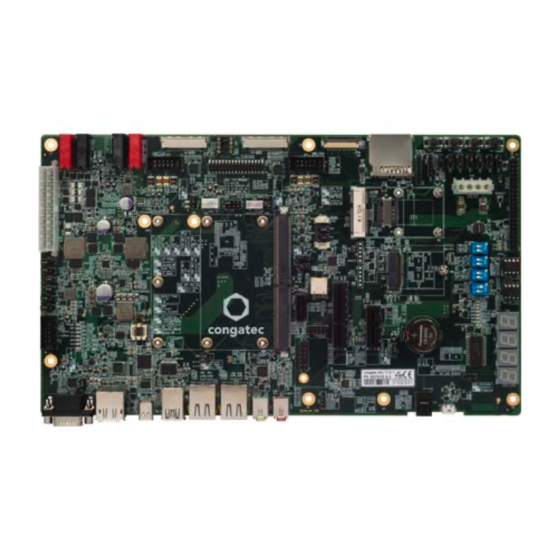
Summary of Contents for Congatec SMARC 2.0 conga-SEVAL
- Page 1 SMARC 2.0 conga-SEVAL ® Detailed description of the congatec SMARC 2.0 evaluation carrier board User’s Guide Revision 1.0 Copyright © 2017 congatec AG SEVALm10 1/58...
-
Page 2: Revision History
Revision History Revision Date (yyyy.mm.dd) Author Changes • 2017.07.05 Preliminary release 2017.10.04 • Corrected the input voltage for connector M24 in table 3 “Connector M23-M24 Descriptions” • Official release Copyright © 2017 congatec AG SEVALm10 2/58... -
Page 3: Intended Audience
In no event shall congatec AG be liable for any incidental, consequential, special, or exemplary damages, whether based on tort, contract or otherwise, arising out of or in connection with this user’s guide or any other information... -
Page 4: Copyright Notice
Copyright © 2017, congatec AG. All rights reserved. All text, pictures and graphics are protected by copyrights. No copying is permitted without written permission from congatec AG. congatec AG has made every attempt to ensure that the information in this document is accurate yet the information contained within is supplied “as-is”. - Page 5 (c) arising from course of performance, course of dealing, or usage of trade. congatec AG shall in no event be liable to the end user for collateral or consequential damages of any kind. congatec shall not otherwise be liable for loss, damage or expense directly or indirectly arising from the use of the product or from any other cause.
-
Page 6: Technical Support
Technical Support congatec AG technicians and engineers are committed to providing the best possible technical support for our customers so that our products can be easily used and implemented. We request that you first visit our website at www.congatec.com for the latest documentation, utilities and drivers, which have been made available to assist you. -
Page 7: Table Of Contents
SPI .................... 28 4.14 SATA ..................49 Boot Selection ................. 29 4.15 HDD Power Connector ............50 Force Recovery ................ 29 Additional Features ..............51 Universal Serial Bus (USB) ............30 Buttons ..................51 Copyright © 2017 congatec AG SEVALm10 7/58... - Page 8 Ground Test Points ..............52 Feature Connector ..............52 Debug Display Port ..............54 GPIO ..................54 JTAG (Debug Feature) - Internal Use Only ......55 Mechanical Dimensions ............57 Industry Specifications ..............Copyright © 2017 congatec AG SEVALm10 8/58...
- Page 9 Jumper X16 Description ............36 Table 54 Jumper X44 Description ............55 Table 27 Connector X13 Pinout Description .......... 37 Table 55 Connector X62 Description ............. 56 Table 28 Connector X18 Pinout Description .......... 38 Copyright © 2017 congatec AG SEVALm10 9/58...
-
Page 10: Introduction
The conga-SEVAL supports both 82 mm x 50 mm and 82 mm x 80 mm SMARC modules and can be used for: • validating SMARC module • evaluating customer platform • debugging or testing production platform • reference purpose Copyright © 2017 congatec AG SEVALm10 10/58... -
Page 11: Connector Layout
Click on the link to navigate to the area in the document where the component is described. Use the mouse icon in the top left hand corner of the destination page to return to the connector layout picture. HDMI DP++ Copyright © 2017 congatec AG SEVALm10 11/58... -
Page 12: Specifications
• 12 V - 24 V DC variable input power supply (connector M23, M24) • 3 V - 5.25 V DC variable input power supply (connector M25, M26) • USB Type-C Power Delivery (12V - 20V) Copyright © 2017 congatec AG SEVALm10 12/58... -
Page 13: Atx/At Power Supply
Power Supply +3.3 VDC Power Ground Table 2 Jumper X53 Description Pin Configuration Jumper X53 ATX Mode (Default) ATX PSU always on Connector Type X51: ATX 2.0 Power Connector X53: 2.54 mm grid jumper Copyright © 2017 congatec AG SEVALm10 13/58... -
Page 14: Dc Power Supply
Carrier board input voltage (12 – 24V) Table 4 Connector M25-M26 Description 3.0V - 5.25V (M25) (M26) Connector Description Ground SMARC module input voltage (3.0V – 5.25V) Connector Type M23 - M26: 4 mm banana plug Copyright © 2017 congatec AG SEVALm10 14/58... -
Page 15: Usb Type-C Power Delivery (Pd)
Use jumper X54 to select the SMARC signal that should enable the runtime voltage of the conga-SEVAL. Jumper X54 Description Configuration Jumper X54 CARRIER_STBY# signal enables carrier board runtime voltages (default) CARRIER_PWRON signal enables carrier board runtime voltages Connector Type X54: 2.54 mm grid jumper Copyright © 2017 congatec AG SEVALm10 15/58... -
Page 16: Standby Voltage Control
Table 6 Jumper X59 Description Configuration Jumper X59 3.3 V Note Jumper X59 has no effect if the module’s supply voltage is via connector M25 and M26. Connector Type X59: 2.54 mm grid jumper Copyright © 2017 congatec AG SEVALm10 16/58... -
Page 17: Power Monitoring (Vin_Pwrbad#)
Setting jumper X61 to position 2-3 switches the module’s power path to connector M25 and M26, even if the conga-SEVAL is powered via M23 and M24. Connector Type X61: 2.54 mm grid jumper Copyright © 2017 congatec AG SEVALm10 17/58... -
Page 18: Status Leds D68 - D71, D73 - D75
This setting ensures the conga-SEVAL enables the necessary DC/DC voltage regulators. Table 10 Jumper X52 Description Jumper X52 Configuration SBM3 present SBM3 not present Table 11 CN3 Description CN3 - Battery Support Pin Signal CHARGING# CHARGER_PRSNT# BATLOW# Copyright © 2017 congatec AG SEVALm10 18/58... -
Page 19: Cmos Battery
X57: 2.54 mm grid jumper Warning Danger of explosion if battery is incorrectly replaced. Replace only with the same or equivalent type recommended by the manufacturer. Dispose of used batteries according to the manufacturer’s instructions. Copyright © 2017 congatec AG SEVALm10 19/58... -
Page 20: Connector Subsystem
CSI0_RX0+ CSI1_RX1- CSI0_RX0- CSI1_RX2+ CSI0_RX1+ CSI1_RX2- CSI0_RX1- CSI1_RX3+ GBE1_MDI0+ CSI1_RX3- GBE1_MDI0- GBE1_LINK100# GBE0_MDI3- GBE1_MDI1+ GBE0_MDI3+ GBE1_MDI1- GBE0_LINK100# GBE1_LINK1000# GBE0_LINK1000# GBE1_MDI2+ GBE0_MDI2- GBE1_MDI2- GBE0_MDI2+ GBE0_LINK_ACT# GBE1_MDI3+ GBE0_MDI1- GBE1_MDI3- GBE0_MDI1+ GBE1_CTREF GBE0_CTREF PCIE_D_TX+ GBE0_MDI0- PCIE_D_TX- Copyright © 2017 congatec AG SEVALm10 20/58... - Page 21 I2C_GP_DAT SATA_TX- HDA_SYNC / I2S2_LRCK HDA_SDO / I2S2_SDOUT SATA_RX+ HDA_SDI / I2S2_SDIN SATA_RX- HDA_CK / I2S2_CK SATA_ACT# ESPI_CS0# USB5_EN_OC# ESPI_CS1# ESPI_IO_2 ESPI_CK ESPI_IO_3 ESPI_IO_1 ESPI_RESET# ESPI_IO_0 USB5+ USB5- USB0+ USB0- USB3_SSTX+ USB0_EN_OC# USB3_SSTX- Copyright © 2017 congatec AG SEVALm10 21/58...
- Page 22 RSVD RSVD USB2_SSRX+ USB3_EN_OC# USB2_SSRX- PCIE_A_RST# PCIE_B_RST# USB4_EN_OC# PCIE_C_RST# RSVD PCIE_C_RX+ RSVD PCIE_C_RX- PCIE_C_REFCK+ PCIE_C_TX+ PCIE_C_REFCK- PCIE_C_TX- PCIE_A_REFCK+ PCIE_B_REFCK+ PCIE_A_REFCK- PCIE_B_REFCK- PCIE_A_RX+ PCIE_B_RX+ PCIE_A_RX- PCIE_B_RX- PCIE_A_TX+ PCIE_B_TX+ PCIE_A_TX- PCIE_B_TX- HDMI_D2+ / DP1_LANE0+ DP0_LANE0+ Copyright © 2017 congatec AG SEVALm10 22/58...
- Page 23 LVDS1_3- / eDP1_TX3- / DSI1_D3- P121 I2C_PM_CK S122 LCD1_BKLT_PWM P122 I2C_PM_DAT S123 RSVD P123 BOOT_SEL0# S124 P124 BOOT_SEL1# S125 LVDS0_0+ / eDP0_TX0+ / DSI0_D0+ P125 BOOT_SEL2# S126 LVDS0_0- / eDP0_TX0- / DSI0_D0- P126 RESET_OUT# S127 LCD0_BKLT_EN Copyright © 2017 congatec AG SEVALm10 23/58...
- Page 24 P149 VDD_IN S150 VIN_PWR_BAD# P150 VDD_IN S151 CHARGING# P151 VDD_IN S152 CHARGER_PRSNT# P152 VDD_IN S153 CARRIER_STBY# P153 VDD_IN S154 CARRIER_PWR_ON P154 VDD_IN S155 FORCE_RECOV# P155 VDD_IN S156 BATLOW# P156 VDD_IN S157 TEST# S158 Copyright © 2017 congatec AG SEVALm10 24/58...
-
Page 25: Communication Buses
Jumper X47 Jumper X49 Configuration Enable 120 Ω resistor termination Disable 120 Ω resistor termination (default) Connector Type X46,X48: 3 x 1 pin header, PicoBlade, 1MM25, SMT X47, X49: 2.54 mm grid jumper Copyright © 2017 congatec AG SEVALm10 25/58... -
Page 26: I2C Bus
2-wire serial EEPROMS (for example 24C04 / 24C08 / 24C16 / 24C32) and can be accessed by using the I²C control commands implemented in the congatec CGOS API driver. Use DIP switch SW1 to configure the EEPROM’s address inputs (A0-A2) and write protect (WP) pin. Switches 1, 2 and 3 of DIP SW1 are set to OFF (high state) by default while switch 4 is set to ON (low state) by default. -
Page 27: Power Management I2C
The conga-SEVAL provides eSPI / SPI signals on connector CN2 for eSPI add-on modules. Table 17 Connector CN2 Description Signal Signal ESPI_CS0# ESPI_CLK_R ESPI_IO3 eSPI / SPI - CN2 Empty ESPI_IO2 Pin 2 ESPI_RST# ESPI_IO1 Pin 1 +V3.3S ESPI_IO0 ESPI_ALERT1# ESPI_CS1# +V3.3A ESPI_ALERT0# Copyright © 2017 congatec AG SEVALm10 27/58... -
Page 28: Spi
Stop SPI communication (pauses the EEPROM) Table 19 Connector X39 Pinout Description Pin Signal Signal +V1.8_SPI SPI0_CS1# SPI Header - X39 GPIO7 SPI0_CLK_HDR SPI0_DOUT_HDR RESET_OUT# SPI0_CS0#_HDR SPI0_DIN_HDR Connector Type X39: 2.54 mm, 2x5 pin female Copyright © 2017 congatec AG SEVALm10 28/58... -
Page 29: Boot Selection
Use jumper X45 to operate the SMARC module in force recovery mode. For more information about this mode, refer to the module’s manual. Table 21 Jumper X45 Description Configuration Jumper X45 Normal operation (default) Force recovery mode Connector Type X45: 2.54 mm grid jumper Copyright © 2017 congatec AG SEVALm10 29/58... -
Page 30: Universal Serial Bus (Usb)
X2 - Micro USB AB USB1 (2.0) X3 - Dual Stacked USB2 (3.0) USB Type A SMARC 2.0 Connector USB3 (2.0) X4 - USB Type-C USB4 (2.0) X11 - M.2 USB5 (2.0) X7 - miniPCIe Copyright © 2017 congatec AG SEVALm10 30/58... -
Page 31: Micro Usb Type-Ab (Otg)
The conga-SEVAL features a USB Type-C port on connector X4. The port supports: USB Type-C - X4 • USB 3.1 specification • USB OTG • DisplayPort • Power Delivery (5 V, 12 V and 20 V) Copyright © 2017 congatec AG SEVALm10 31/58... -
Page 32: Pcie
PCIe Link B PCIe Link C PCIe Link D Stuffing Options M.2 (X11) PCIe Lane B Mini PCIe (X7) SIM Card Slot (X8) PCIe Lane C PCIe x1 lane (X9) PCIe Lane D Copyright © 2017 congatec AG SEVALm10 32/58... -
Page 33: Pcie X4 Slot
Mini PCIe - Connector X7 Connector Type X7: Mini PCIe card 4.5.3 PCIe x1 Slot The conga-SEVAL provides a PCIe x1 slot on connector X9. PCIe x1 - X9 Connector Type X9: PCIe x1 card Copyright © 2017 congatec AG SEVALm10 33/58... -
Page 34: Table 22 Dip Switch M11 Description
2. UART devices on the feature connector will not function if any card is inserted into the M.2 connector. Connector Type X11: M.2 Key E slot (compatible with card size 1630, 2230 and 3030) Copyright © 2017 congatec AG SEVALm10 34/58... -
Page 35: Sim Card Slot
SD Card Slot - CN1 Signal Signal SDIO_WP +V3.3S_SDIO SDIO_CD# SDIO_D1 SDIO_D0 SDIO_CMD SDIO_D3 SDIO_D2 SDIO_CLK Note SDIO based cards will not function on the M.2 connector if an SD card is inserted into connector CN1. Copyright © 2017 congatec AG SEVALm10 35/58... -
Page 36: Gigabit Ethernet (Gbe)
Status LEDs are powered by standby voltage Status LEDs are powered by runtime voltage Connector Type X12, X15: RJ45 with Gigabit Magnetic and LEDs (TYCO 2250015) X14: 2.54 mm, 1 x 4-pin header X16: 2.54 mm grid jumper Copyright © 2017 congatec AG SEVALm10 36/58... -
Page 37: Mipi-Csi
CSI0_I2C_CLK MIPI - Connector X13 CSI1_RX1+ CSI0_I2C_DAT CSI1_RX1- CSI0_CLK+ CSI1_RX2+ CSI0_CLK CSI1_RX2- CSI1_RX3+ CSI0_RX0+ CSI1_RX3- CSI0_RX0- GPIO3/CAM1_RST# GPIO2/CAM0_RST# CSI0_RX1+ CSI1_CLK+ CSI0_RX1- CSI1_CLK CSI1_I2C_CLK Connector Type X13: 0.5 mm pitch, 36-pin flat foil connector Copyright © 2017 congatec AG SEVALm10 37/58... -
Page 38: Serial Ports
Connector Type X18: 9-pin D-Sub connector 4.10.2 COM Port 1 COM port 1 supports RS 232 I/O voltage levels. Table 29 Connector X17 Pinout Description Pin Signal Signal COM Port 1 - X17 SER1_RXD Copyright © 2017 congatec AG SEVALm10 38/58... -
Page 39: Com Port 2
Use jumper X43 to set the supply voltage of the attached cooling fan to 5 V or 12 V. Table 30 Connector X42 Pinout Description FAN - X42 Pin Signal FAN_PWR (12 V or 5 V) FAN_TACHO FAN_PWM Copyright © 2017 congatec AG SEVALm10 39/58... -
Page 40: Audio Interfaces
Use switch 1 of DIP switch M12 to select I S or HDA codec. Table 32 I2S or HDA Codec Selection DIP Switch M12 Configuration SW 1 SW 2 I²S codec HDA codec Copyright © 2017 congatec AG SEVALm10 40/58... -
Page 41: Mic-In
Line OUT - X21 Pin Jack Signal Description LINE_L Line-OUT - left channel Ring Ring LINE_R Line-OUT - right channel Sleeve Sleeve A_GND Analog ground Connector Type X21: 3-pin, 3.5 mm single audio jack Copyright © 2017 congatec AG SEVALm10 41/58... -
Page 42: S/Pdif Out
• Native HDMI on connector X33 (lower port) • DisplayPort alternate mode on USB Type C connector X4 • eDP / LVDS / DSI – eDP on connector X31 or X32 or both – LVDS / DSI on connector X23 Copyright © 2017 congatec AG SEVALm10 42/58... -
Page 43: Displayport
• set jumper X34 to position 2-3 Table 36 Jumper X34 Pin Description Jumper X34 Configuration DisplayPort on USB Type-C connector (X4) HDMI (default) Connector Type X33: DP/HDMI cable X34: 2.54 mm grid jumper Copyright © 2017 congatec AG SEVALm10 43/58... -
Page 44: Usb Type C Alternate Display Mode
Configuration DisplayPort on USB Type-C connector (X4) HDMI Table 38 Jumper X35 Pin Description Jumper X35 Configuration DisplayPort AUX HDMI DDC Connector Type X4: USB Type-C Receptacle X34, X35: 2.54 mm grid jumper Copyright © 2017 congatec AG SEVALm10 44/58... -
Page 45: Lvds / Dsi / Edp
SW 2 eDP selection LVDS / DSI selection Table 40 Connector X31 / X32 Pinout Description Signal Signal N.C. VCC_EDP_FILT N.C. eDP[0:1]_TX3- eDP[0:1]_TX3+ eDP Connector - X31 / X32 eDP[0:1]_TX2- eDP[0:1]_TX2+ eDP[0:1]_HPD eDP[0:1]_TX1- eDP[0:1]_TX1+ Copyright © 2017 congatec AG SEVALm10 45/58... -
Page 46: Lvds / Dsi
• set switch 2 of DIP switch M12 to OFF position Table 41 Connector X31 / X32 Pinout Description Dip Switch M12 Configuration SW 1 SW 2 eDP selection LVDS / DSI selection Copyright © 2017 congatec AG SEVALm10 46/58... -
Page 47: Flat Panel And Backlight Power Supply
The conga-SEVAL provides the following power supply connectors for panels and backlight inverters: • connector X26 for LVDS panel connected to X23 or eDP panel connected to X31 • connector X30 for eDP panel connected to X32 Copyright © 2017 congatec AG SEVALm10 47/58... -
Page 48: Flat Panel And Backlight Voltage Selection
– jumper X28 to set the backlight voltage to 5 V or 12 V – jumper X29 to change the polarity of backlight enable signal Table 44 Jumper X22 / X27 Pinout Description Configuration Jumper X22 / X27 3.3 V panel power 5 V panel power Copyright © 2017 congatec AG SEVALm10 48/58... -
Page 49: Sata
The conga-SEVAL provides a standard SATA connector (X50). The SATA activity LED (D50) glows when an activity occurs on this interface. Table 47 Connector X50 Description Pin Signal SATA - X50 SATA_TX+ SATA_TX- SATA_RX SATA_RX+ Connector Type X50: Standard SATA connector Copyright © 2017 congatec AG SEVALm10 49/58... -
Page 50: Hdd Power Connector
The conga-SEVAL provides connector X58 for powering hard disks. Use this connector when operating in non-ATX mode. Table 48 Connector X58 Description Pin Signal HDD Power - X58 +12 V (1.5 A Fuse) +5 V (2.0 A Fuse) Connector Type X58: 5.08 mm, 4-pin female connector Copyright © 2017 congatec AG SEVALm10 50/58... -
Page 51: Additional Features
RESET_IN# signal. Reset - M20 5.1.3 You can trigger the LID# signal by pressing the lid button M21. The system’s behaviour depends on the ACPI settings of the Operating System. Lid - M21 Copyright © 2017 congatec AG SEVALm10 51/58... -
Page 52: Sleep
PS_ON# Power supply on (active low) GPIO6_3V3 General purpose input/output port 6 CARRIER_ Indicates the system is in Suspend to GPIO7_3V3 General purpose input/output port 7 STBY#_3V# RAM state Power ground Power ground Copyright © 2017 congatec AG SEVALm10 52/58... - Page 53 Serial port 2 request to send SER2_RX Serial port 2 receive line SER2_CTS Serial port 2 clear to send Feature Connector X37 Pin 2 Pin 1 Connector Type X37: 2.54 mm, 2 x 22 pin header Copyright © 2017 congatec AG SEVALm10 53/58...
-
Page 54: Debug Display Port
GPIO connector X38, JTAG connector X62 or MIPI connector X13 GPIO4 HDA_RST# Audio connector or feature connector X37 GPIO5 PWM_OUT Fan connector X42 or feature connector X37 GPIO6 TACHIN Fan connector X42 or feature connector X37 GPIO[7:11] Feature connector X37 Copyright © 2017 congatec AG SEVALm10 54/58... -
Page 55: Jtag (Debug Feature) - Internal Use Only
X40: 2.54 mm grid jumper JTAG (Debug Feature) - Internal Use Only The conga-SEVAL provides a JTAG interface on connector X62. This interface is used for programming and debugging the congatec board controller. Set jumper X44 to position 1-2 for normal operation. -
Page 56: Table 55 Connector X62 Description
Table 55 Connector X62 Description Signal +V3.3 JTAG for CGBC - X62 Pin 1 TEST#_EN (jumper X44) Connector Type X62: 2.54 mm, 1x7 pin header X44: 2.54 mm grid jumper Copyright © 2017 congatec AG SEVALm10 56/58... -
Page 57: Mechanical Dimensions
Mechanical Dimensions 293.4 288.9 209.55 163.83 135.82 101.8 93.91 71.8 63.71 6.35 Copyright © 2017 congatec AG SEVALm10 57/58... -
Page 58: Industry Specifications
LVDS Owner’s Manual http://www.ti.com/lit/ml/snla187/snla187.pdf Extended Display Identification Data Standard (EDID™) http://www.vesa.org Enhanced Display Data Channel Specification (DDC) http://www.vesa.org IEEE standard 802.3ab 1000BASE T Ethernet http://www.ieee.org/portal/site Advanced Configuration and Power Interface Specification http://www.acpi.info Copyright © 2017 congatec AG SEVALm10 58/58...
Need help?
Do you have a question about the SMARC 2.0 conga-SEVAL and is the answer not in the manual?
Questions and answers