
Related Manuals for Congatec Conga-TCA


Summary of Contents for Congatec Conga-TCA
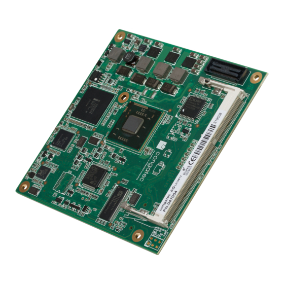
- Page 1 COM Express™ conga-TCA 2nd Generation Dual Core Intel Atom™ processor with an Intel NM10 express chipset ® ® User’s Guide Revision 1.1 Copyright © 2015 congatec AG TCEDm11 1/96...
-
Page 2: Revision History
Updated section 1.3 “Mechanical Dimension” and section 3 “Heatspreader” to reflect the actual heatspreader thickness of 4mm • Corrected the statement that the Intel® CG82NM10 (NM10) PCH found on the conga-TCA offers a single channel LVDS interface in section 4.1.10 “LCD” •... -
Page 3: Intended Audience
In no event shall congatec AG be liable for any incidental, consequential, special, or exemplary damages, whether based on tort, contract or otherwise, arising out of or in connection with this user’s guide or any other information... -
Page 4: Copyright Notice
Copyright © 2012, congatec AG. All rights reserved. All text, pictures and graphics are protected by copyrights. No copying is permitted without written permission from congatec AG. congatec AG has made every attempt to ensure that the information in this document is accurate yet the information contained within is supplied “as-is”. - Page 5 (c) arising from course of performance, course of dealing, or usage of trade. congatec AG shall in no event be liable to the end user for collateral or consequential damages of any kind. congatec shall not otherwise be liable for loss, damage or expense directly or indirectly arising from the use of the product or from any other cause.
-
Page 6: Technical Support
Technical Support congatec AG technicians and engineers are committed to providing the best possible technical support for our customers so that our products can be easily used and implemented. We request that you first visit our website at www.congatec.com for the latest documentation, utilities and drivers, which have been made available to assist you. -
Page 7: Table Of Contents
Cache ..................16 Additional Features ..............30 2.5.3 conga-TCA Intel ® Atom™ D2550 Dual Core 1.86 GHz 1MB congatec Board Controller (cBC) ..........30 Cache ..................17 Board Information ..............30 2.5.4 conga-TCA Intel ® Atom™ D2550 (USB 3.0) Dual Core 1.86 GHz Watchdog ................ - Page 8 ACPI Submenu ................. 79 10.4.6 RTC Wake Settings Submenu ..........80 10.4.7 CPU Submenu ................80 10.4.8 Memory Submenu ..............81 10.4.9 Chipset Submenu ..............82 10.4.9.1 IO Hub Devices Submenu ............82 Copyright © 2015 congatec AG TCEDm11 8/96...
- Page 9 Table 30 IRQ Lines in PIC mode ............. 67 Table 31 IRQ Lines in APIC mode ............68 Table 32 PCI Configuration Space Map ..........69 Table 33 PCI Interrupt Routing Map ............70 Copyright © 2015 congatec AG TCEDm11 9/96...
-
Page 10: Introduction
8 / 0 1x DDI The conga-TCA modules use the Type 6 pinout definition and comply with COM Express 2.1 specification. They are equipped with two high performance connectors that ensure stable data throughput. The COM integrates all the core components and is mounted onto an application specific carrier board. COM modules are legacy-free design (no Super I/O, PS/2 keyboard and mouse) and provide most of the functional requirements for any application. - Page 11 Options Information The conga-TCA has four variants. The table below shows the different configurations available. Check for the Part No. that applies to your product. This will tell you what options described in this user’s guide are available on your particular module.
-
Page 12: Specifications
2.5 Gb/s bandwidth in each direction per x1 link SM Bus BIOS AMI Aptio ® UEFI 2.x firmware, 4MByte serial SPI with congatec Embedded BIOS features Power ACPI 3.0 compliant with battery support. Also supports Suspend to RAM (S3). Management Note Some of the features mentioned in the above Feature Summary are optional. -
Page 13: Supported Operating Systems
Supported Operating Systems The conga-TCA supports the following operating systems. • Microsoft Windows 8 (32 bit) ® ® • Microsoft ® Windows ® • Microsoft ® Windows ® • Microsoft Windows Embedded Standard ® ® • Linux Note The graphics driver for Microsoft ®... -
Page 14: Supply Voltage Standard Power
The input voltages shall rise from 10% of nominal to 90% of nominal at a minimum rise time of 250V/s. The smooth turn-on requires that, during the 10% to 90% portion of the rise time, the slope of the turn-on waveform must be positive. Copyright © 2015 congatec AG TCEDm11... -
Page 15: Power Consumption
The power consumption values listed in this document were measured under a controlled environment. The hardware used for testing includes a conga-TCA module, conga-Cdebug carrier board, CRT monitor, SATA drive, and USB keyboard. The conga-Cdebug is modified so that the 12V input is only routed to the module and all other circuity on the carrier itself is powered by the 5V input. The SATA drive was powered externally by an ATX power supply so that it does not influence the power consumption value that is measured for the module. -
Page 16: Conga-Tca Intel ® Atom™ N2600 Dual Core 1.6 Ghz 1Mb Cache
Processor Information The tables below provide additional information about the power consumption data for each of the conga-TCA variants offered. The values are recorded at various operating mode. 2.5.1 conga-TCA Intel Atom™ N2600 Dual Core 1.6 GHz 1MB Cache ®... -
Page 17: Conga-Tca Intel ® Atom™ D2550 Dual Core 1.86 Ghz 1Mb Cache
2.5.3 conga-TCA Intel Atom™ D2550 Dual Core 1.86 GHz 1MB Cache ® conga-TCA Art. No. 047003 Intel Atom™ D2550 1.86 GHz 1MB L2 Cache 32nm ® Layout Rev. TCEDLA0 /BIOS Rev. TCEDR006 Max Turbo Frequency Not supported Memory Size Operating System... -
Page 18: Supply Voltage Battery Power
Storage: 5% to 95% Caution The above operating temperatures must be strictly adhered to at all times. When using a congatec heatspreader, the maximum operating temperature refers to any measurable spot on the heatspreader’s surface. Humidity specifications are for non-condensing conditions. -
Page 19: Block Diagram
® Intel NM10 ® Processor Express Chipset N2800 x2 (N2000) CG82NM10 PCH congatec x4 (D2000) N2600 GPIs/GPOs Board Controller D2550 STM32F100R8 SM Bus PCIe2USB3 DDR3-SODIMM max. 4 GByte Memory Types (up to 1066MTs) Copyright © 2015 congatec AG TCEDm11 19/96... -
Page 20: Heatspreader
Caution Provide active airflow for the cooling fins of the conga-TCA/CSP-T(B) when you use the cooler on variants with PN: 047003 or PN: 047004. The cooler cannot dissipate the heat generated by these modules without an active airflow. Copyright © 2015 congatec AG... -
Page 21: Heatspreader Dimensions
Heatspreader Dimensions Note All measurements are in millimeters. Torque specification for heatspreader screws is 0.3 Nm. Mechanical system assembly mounting shall follow the valid DIN/IS0 specifications. Copyright © 2015 congatec AG TCEDm11 21/96... -
Page 22: Connector Subsystems Rows A, B, C, D
Connector Subsystems Rows A, B, C, D The conga-TCA is connected to the carrier board via two 220-pin connectors (COM Express Type 6 pinout) for a total of 440 pins connectivity. These connectors are broken down into four rows. The primary connector consists of rows A and B while the secondary connector consists of rows C and D. -
Page 23: Primary Connector Rows A And B
5.1.2 USB 2.0 The conga-TCA offers one EHCI USB host controller that supports USB high speed signalling and four UHCI host controllers that supports both low and full speed signalling through Intel CG82NM10 (NM10) PCH. These controllers comply with USB standard 1.1 and 2.0 and offer a total ®... -
Page 24: Lpc Bus
PCI Express™ lanes if the optional USB 3.0 is not implemented. The Gen1 PCI Express™ interface offers support for full 2.5 Gb/s bandwidth in each direction per x1 link. The conga-TCA also has a sixth PCI Express™ lane that is utilized by the onboard Gigabit Ethernet interface and therefore not available externally. -
Page 25: Lcd
• resolution up to 1366x768 for 18 bpp and up to 1440x900 for 24 bpp 5.1.11 A SPI interface that supports booting from an external SPI flash is available on the conga-TCA via the Intel CG82NM10 (NM10) PCH . The ®... -
Page 26: Power Control
(typically 100ms) after all carrier board power rails are up, to ensure a stable system. See screenshot below. Note The module is kept in reset as long as the PWR_OK is driven by carrier board hardware. Copyright © 2015 congatec AG TCEDm11 26/96... - Page 27 0.8V when the 12V is applied to the module. Actively driving PWR_OK high is compliant to the COM Express specification but this can cause back driving. Therefore, congatec recommends driving the PWR_OK low to keep the module in reset and tri-state PWR_OK when the carrier board hardware is ready to boot.
-
Page 28: Power Management
Power Supply Implementation Guidelines 12 volt input power is the sole operational power source for the conga-TCA. The remaining necessary voltages are internally generated on the module using onboard voltage regulators. A carrier board designer should be aware of the following important information when designing a power supply for a conga-TCA application: •... -
Page 29: Secondary Connector Rows C And D
DisplayPort (DP) The conga-TCA offers two DP ports, each capable of supporting link-speeds of 1.62 Gbps and 2.7 Gbps on 1, 2 or 4 data lanes. The DP is multiplexed onto the Digital Display Interface (DDI) of the COM Express connector. The DisplayPort specification is a VESA standard aimed at consolidating internal and external connection methods to reduce device complexity, supporting key cross industry applications, and providing performance scalability to enable the next generation of displays. -
Page 30: Additional Features
Note The conga-TCA module does not support the watchdog NMI mode. COM Express type 6 modules do not support the PCI bus and therefore the PCI_SERR# signal is not available. There is no way to drive a NMI to the processor without the presence of the PCI_SERR# PCI bus signal. -
Page 31: Power Loss Control
OEM BIOS Code With the congatec embedded BIOS it is even possible for system designers to add their own code to the BIOS POST process. Except for custom specific code, this feature can also be used to support Win XP SLP installation, Window 7 SLIC table, verb tables for HDA codecs, rare graphic modes and Super I/O controllers. -
Page 32: Congatec Battery Management Interface
EAPI (Embedded Application Programming Interface) is a programming interface defined by the PICMG that addresses this problem. With this unified API, it is now possible to run the same application on all vendor’s COMs that offer EAPI driver support. Contact congatec technical support for more information about EAPI. -
Page 33: Security Features
Security Features The conga-TCA can be equipped optionally with a “Trusted Platform Module“ (TPM 1.2). This TPM 1.2 includes coprocessors to calculate efficient hash and RSA algorithms with key lengths up to 2,048 bits as well as a real random number generator. Security sensitive applications like gaming and e-commerce will benefit also with improved authentication, integrity and confidence levels. -
Page 34: Conga Tech Notes
Tech Notes The conga-TCA has some technological features that require additional explanation. The following section will give the reader a better understanding of some of these features. This information will also help to gain a better understanding of the information found in the System Resources section of this user’s guide as well as some of the setup nodes found in the BIOS Setup Program description section. -
Page 35: Processor Performance Control
In order for THERMTRIP# to be able to automatically switch off the system, it is necessary to use an ATX style power supply. 7.2.2 Processor Performance Control Intel Atom™ D2000/N2000 series processors found on the conga-TCA run at different voltage/frequency states (performance states), which ® is referred to as Enhanced Intel SpeedStep technology (EIST). - Page 36 • The two coefficients TC1 and TC2 and the sampling period TSP are hardware dependent constants. These constants are set to fixed values for the conga-TCA: • TC1= 1 • TC2= 5 • TSP= 5 seconds See section 12 of the ACPI Specification 2.0 C for more information about passive cooling. Copyright © 2015 congatec AG TCEDm11 36/96...
-
Page 37: Acpi Suspend Modes And Resume Events
ACPI Suspend Modes and Resume Events conga-TCA supports S3 (STR= Suspend to RAM). For more information about S3 wake events see section 10.4.5 “ACPI Submenu”. S4 (Suspend to Disk) is not supported by the BIOS (S4_BIOS) but it is supported by the following operating systems (S4_OS= Hibernate): •... -
Page 38: Usb 2.0 Ehci Host Controller Support
UHCI #3 UHCI #2 UHCI #1 UHCI #0 (D29:F3) (D29:F2) (D29:F1) (D29:F0) Port 7 Port 6 Port 5 Port 4 Port 3 Port 2 Port 1 Port 0 Debug Enhanced Host Controller Logic Port Copyright © 2015 congatec AG TCEDm11 38/96... -
Page 39: Signal Descriptions And Pinout Tables
Signal Descriptions and Pinout Tables The following section describes the signals found on COM Express™ Type VI connectors used for congatec AG modules. The pinout of the modules complies with COM Express Type 6.0 Rev. 2.1. Table 2 describes the terminology used in this section for the Signal Description tables. The PU/PD column indicates if a COM Express™... -
Page 40: A-B Connector Signal Descriptions
High Definition Audio. ® Note Some signals have special functionality during the reset process. They may bootstrap some basic important functions of the module. For more information refer to section 8.5 of this user’s guide. Copyright © 2015 congatec AG TCEDm11 40/96... -
Page 41: Table 4 Gigabit Ethernet Signal Descriptions
The GBE0_LINK# output is only active during a 100Mbit or 1Gbit connection, it is not active during a 10Mbit connection. This is a limitation of Ethernet controller since it only has 3 LED outputs, ACT#, LINK100# and LINK1000#. The GBE0_LINK# signal is a logic AND of the GBE0_LINK100# and GBE0_LINK1000# signals on the conga-TCA module. Copyright © 2015 congatec AG... -
Page 42: Table 5 Serial Ata Signal Descriptions
Serial ATA channel 3, Receive Input differential pair. I SATA Not supported SATA3_RX- SATA3_TX+ Serial ATA channel 3, Transmit Output differential pair. O SATA Not supported SATA3_TX- (S)ATA_ACT# ATA (parallel and serial) or SAS activity indicator, active low. I/O 3.3v Copyright © 2015 congatec AG TCEDm11 42/96... -
Page 43: Table 6 Pci Express Signal Descriptions (General Purpose)
PCI Express Reference Clock output for all PCI Express O PCIE A PCI Express compliant clock buffer chip must be used on the PCIE_CLK_REF- and PCI Express Graphics Lanes. carrier board if more than one PCI Express device is designed in. Copyright © 2015 congatec AG TCEDm11 43/96... -
Page 44: Table 7 Expresscard Support Pins Descriptions
LPC_CLK is a bootstrap signal Note Some signals have special functionality during the reset process. They may bootstrap some basic important functions of the module. For more information refer to section 8.5 of this user’s guide. Copyright © 2015 congatec AG TCEDm11 44/96... -
Page 45: Table 9 Usb Signal Descriptions
Do not pull this line high on the carrier board. be present on the module. An open drain driver from a USB current 3.3VSB 3.3VSB monitor on the carrier board may drive this line low. Copyright © 2015 congatec AG TCEDm11 45/96... -
Page 46: Table 10 Crt Signal Descriptions
DDC lines used for flat panel detection and control. O 3.3V PU 2k2 3.3V LVDS_I2C_DAT DDC lines used for flat panel detection and control. I/O 3.3V PU 2k2 3.3V LVDS_I2C_DAT is a boot strap signal (see note below). Copyright © 2015 congatec AG TCEDm11 46/96... -
Page 47: Table 12 Spi Bios Flash Interface Signal Descriptions
PU 10k Carrier shall pull to GND or leave no-connect. 3.3VSB BIOS_DIS1# Selection strap to determine the BIOS boot device. I 3.3VSB PU 10k Carrier shall pull to GND or leave no-connect 3.3VSB Copyright © 2015 congatec AG TCEDm11 47/96... -
Page 48: Table 13 Miscellaneous Signal Descriptions
PU/PD Comment GPO0 General purpose output pins. O 3.3V SDIO interface is not supported on the conga-TCA Shared with SD_CLK. Output from COM Express, input to SD GPO1 General purpose output pins. O 3.3V SDIO interface is not supported on the conga-TCA Shared with SD_CMD. -
Page 49: Table 15 Power And System Management Signal Descriptions
I OD 3.3V PU 10k 3.3VSB SLEEP# B103 Sleep button. Used by the ACPI operating system to bring the system to sleep state or to wake I OD 3.3V PU 10k 3.3VSB it up again. Copyright © 2015 congatec AG TCEDm11 49/96... -
Page 50: Table 16 General Purpose Serial Interface Signal Descriptions
All available GND connector pins shall be used and tied to Carrier Board GND plane. A66, A70, A80, A90, A100, A110, B1, B11, B21, B31, B41, B51, B60, B70, B80, B90, B100, B110 Copyright © 2015 congatec AG TCEDm11 50/96... -
Page 51: A-B Connector Pinout
LVDS_BKLT_EN SATA2_RX+ (*) SATA3_RX+ (*) GND (FIXED) GND (FIXED) SATA2_RX- (*) SATA3_RX- (*) LVDS_A_CK+ LVDS_B_CK+ (*) BATLOW# LVDS_A_CK- LVDS_B_CK- (*) (S)ATA_ACT# AC/HDA_SDIN2 (*) LVDS_I2C_CK LVDS_BKLT_CTRL AC/HDA_SYNC AC/HDA_SDIN1 LVDS_I2C_DAT VCC_5V_SBY AC/HDA_RST# AC/HDA_SDIN0 GPI3 VCC_5V_SBY Copyright © 2015 congatec AG TCEDm11 51/96... - Page 52 A108 VCC_12V B108 VCC_12V GPI0 GPO1 A109 VCC_12V B109 VCC_12V PCIE_TX4+ PCIE_RX4+ A110 GND (FIXED) B110 GND (FIXED) Note The signals marked with an asterisk symbol (*) are not supported on the conga TCA. Copyright © 2015 congatec AG TCEDm11 52/96...
-
Page 53: C-D Connector Signal Descriptions
Additional receive signal differential pairs for the Superspeed USB data path I Not supported USB_SSRX3- Not supported USB_SSTX3+ Additional transmit signal differential pairs for the Superspeed USB data Not supported path USB_SSTX3- Not supported Copyright © 2015 congatec AG TCEDm11 53/96... -
Page 54: Table 21 Pci Express Signal Descriptions (X16 Graphics)
Note USB 3.0 is only supported on PN: 047004 conga-TCA/D2550 xHCI modules. Table 21 PCI Express Signal Descriptions (x16 Graphics) Signal Pin # Description PU/PD Comment PEG_RX0+ PCI Express Graphics Receive Input differential pairs. I PCIE Not supported Note: Can also be used as PCI Express Receive Input differential pairs 16 through 31 known PEG_RX0- as PCIE_RX[16-31] + and -. - Page 55 D101 PEG_TX15- D102 PEG_LANE_RV# PCI Express Graphics lane reversal input strap. Pull low on the carrier board to reverse lane Not supported order. Note PCI Express Graphics is not supported on conga-TCA modules Copyright © 2015 congatec AG TCEDm11 55/96...
-
Page 56: Table 22 Ddi Signal Description
Multiplexed with DP2_LANE2+ and TMDS2_DATA0+. O PCIE DDI2_PAIR2- Multiplexed with DP2_LANE2- and TMDS2_DATA0-. DDI2_PAIR3+ Multiplexed with DP2_LANE3+ and TMDS2_CLK+. O PCIE DDI2_PAIR3- Multiplexed with DP2_LANE3- and TMDS2_CLK-. DDI2_HPD Multiplexed with DP2_HPD and HDMI2_HPD. I 3.3V PD 1M Copyright © 2015 congatec AG TCEDm11 56/96... - Page 57 The Digital Display Interface (DDI) signals are multiplexed with HDMI, DisplayPort (DP) and SDVO. The signals for these interfaces are routed to the DDI interface of the COM Express connector. The SDVO interface is however not supported on the conga-TCA.
-
Page 58: Table 23 Hdmi Signal Descriptions
TMDS3_CLK + HDMI/DVI TMDS Clock output differential pair.. O PCIE Not supported TMDS3_CLK - Multiplexed with DDI3_PAIR3+ and DDI3_PAIR3-. TMDS3_DATA0+ HDMI/DVI TMDS differential pair. O PCIE Not supported TMDS3_DATA0- Multiplexed with DDI3_PAIR2+ and DDI3_PAIR2-. Copyright © 2015 congatec AG TCEDm11 58/96... -
Page 59: Table 24 Displayport (Dp) Signal Descriptions
EDID access. PCIE 3.3V DP enable strap is already populated. DP2_LANE3+ Uni-directional main link for the transport of isochronous streams and O PCIE DP2_LANE3- secondary data. Multiplexed with DDI2_PAIR3+ and DDI2_PAIR3- Copyright © 2015 congatec AG TCEDm11 59/96... - Page 60 EDID access. PCIE Note Some signals have special functionality during the reset process. They may bootstrap some basic important functions of the module. For more information refer to section 8.5 of this user’s guide. Copyright © 2015 congatec AG TCEDm11 60/96...
-
Page 61: Table 25 Module Type Definition Signal Description
Type 2-6 TYPE2# TYPE1# TYPE0# Pinout standard. Pinout Type 1 The conga-TCA is based Pinout Type 2 on the COM Express Pinout Type 3 (no IDE) Type 6 pinout therefore Pinout Type 4 (no PCI) the pins 0 and 1 are not... -
Page 62: C-D Connector Pinout
DDI1_PAIR4+ (*) RSVD GND (FIXED) GND (FIXED) DDI1_PAIR4- (*) DDI1_PAIR0+ PEG_RX9+ (*) PEG_TX9+ (*) RSVD DDI1_PAIR0- PEG_RX9- (*) PEG_TX9- (*) RSVD RSVD RSVD RSVD DDI1_PAIR5+ (*) DDI1_PAIR1+ DDI1_PAIR5- (*) DDI1_PAIR1- PEG_RX10+ (*) PEG_TX10+ (*) Copyright © 2015 congatec AG TCEDm11 62/96... - Page 63 D108 VCC_12V TYPE0# PEG_LANE_RV# C109 VCC_12V D109 VCC_12V PEG_RX1+ (*) PEG_TX1+ (*) C110 GND (FIXED) D110 GND (FIXED) Note The signals marked with an asterisk symbol (*) are not supported on the conga-TCA. Copyright © 2015 congatec AG TCEDm11 63/96...
-
Page 64: Boot Strap Signals
No external DC loads or external pull-up or pull-down resistors should change the configuration of the signals listed in the above table. External resistors may override the internal strap states and cause the COM Express™ module to malfunction and/ or cause irreparable damage to the module. Copyright © 2015 congatec AG TCEDm11 64/96... -
Page 65: System Resources
I/O Address Assignment The I/O address assignment of the conga-TCA module is functionally identical with a standard PC/AT. The BIOS assigns PCI and PCI Express I/O resources from FFF0h downwards. Non PnP/PCI/PCI Express compliant devices must not consume I/O resources in that area. -
Page 66: Lpc Bus
LPC Bus On the conga-TCA, the internal PCI Bus acts as the subtractive decoding agent. All I/O cycles that are not positively decoded are forwarded to the internal PCI Bus. Only specified I/O ranges are forwarded to the LPC Bus by default. -
Page 67: Interrupt Request (Irq) Lines
IRQ12 via SERIRQ or PCI BUS INTx Math processor Not applicable PCI BUS INTx PCI BUS INTx Note In PIC mode, the PCI bus interrupt lines can be routed to any free IRQ. Copyright © 2015 congatec AG TCEDm11 67/96... -
Page 68: Table 31 Irq Lines In Apic Mode
PIRQH, EHCI Host Controller #1, UHCI Controller #0, COMx Slot #0, COMx Slot #1, COMx Slot #2, COMx Slot #3 Note In APIC mode, the PCI bus interrupt lines are connected with IRQ 16, 17, 18 and 19. Copyright © 2015 congatec AG TCEDm11 68/96... -
Page 69: Pci Configuration Space Map
Note 1. The PCI Express Ports are visible only if a device is attached behind them to the PCI Express Slot on the base board. 2. This device is only present on some conga-TCA variants. Copyright © 2015 congatec AG... -
Page 70: Pci Interrupt Routing Map
These interrupt lines are virtual (message based) I²C Bus There are no onboard resources connected to the I²C bus. Address 16h is reserved for congatec Battery Management solutions. SM Bus System Management (SM) bus signals are connected to the Intel CG82NM10 (NM10) PCH and the SM bus is not intended to be used by ®... -
Page 71: Bios Setup Description
POST allowing the operator to select either the boot device that should be used or an option to enter the BIOS setup program. 10.2 Setup Menu and Navigation The congatec BIOS setup screen is composed of the menu bar and two main frames. The menu bar is shown below: Main Advanced Boot Security Save &... -
Page 72: Main Setup Screen
Serial Number no option Displays the serial number of the board. BC Firmware Rev. no option Displays the revision of the congatec board controller. MAC Address no option Displays the MAC address of the onboard Ethernet controller. Boot Counter no option Displays the number of boot-ups. -
Page 73: Intel Rc Version Submenu
Main Advanced Boot Security Save & Exit Graphics Watchdog Hardware Monitoring ACPI RTC Wake Memory Chipset SATA iFFS Super IO Console Redirection Network Stack Copyright © 2015 congatec AG TCEDm11 73/96... -
Page 74: Graphics Submenu
Auto detection is performed by reading an EDID data set via the video I²C bus. WVGA 800x480 1x24 (01Bh) The number in brackets specifies the congatec internal number of the respective panel data set. Note: Customized EDID™ utilizes an OEM defined EDID™ data set stored in the BIOS flash device. -
Page 75: Watchdog Submenu
5min 10min 30min Event 1 ACPI Event Selects the type of event that will be generated when timeout 1 is reached. For more information about ACPI Event, see note Reset below. Power Button Copyright © 2015 congatec AG TCEDm11 75/96... - Page 76 Note In ACPI mode it is not possible for a “Watchdog ACPI Event” handler to directly restart or shutdown the OS. For this reason, the congatec BIOS will do one of the following: For Shutdown: An over temperature notification is executed. This causes the OS to shut down in an orderly fashion.
-
Page 77: Hardware Monitoring Submenu
Select maximum/end fan speed to be ramped up to until the end temperature of the control slope is reached. Only 20%, 25%, 30%, 35%, visible if Automatic Fan Speed Control is enabled. 40%, 45%, 50%, 55%, 60%, 65%, 70%, 75%, 80%, 85%, 90%, 95% 100% Copyright © 2015 congatec AG TCEDm11 77/96... -
Page 78: Pci Submenu
IRQ10, IRQ11 Reserve Legacy Interrupt 2 Same as Reserve Same as Reserve Legacy Interrupt 1 Legacy Interrupt 1 ►PIRQ Routing & IRQ submenu Manual PIRQ routing and interrupt reservation for legacy devices. Reservation Copyright © 2015 congatec AG TCEDm11 78/96... -
Page 79: Pirq Routing & Irq Reservation Submenu
Specifies the temperature threshold at which the ACPI aware OS performs a critical shutdown. The option “POR” 100, 105, 110, 115, 120, is for Cedar Trail Processor at 100° C trip point. 125 °C, Disabled Copyright © 2015 congatec AG TCEDm11 79/96... -
Page 80: Rtc Wake Settings Submenu
Disabled Enable or disable EIST support. Enabled CPU C State Report Disabled Enable or disable CPU C state report to OS. Enabled Enhanced C State Disabled Enable or disable CPU C state. Enabled Copyright © 2015 congatec AG TCEDm11 80/96... -
Page 81: Memory Submenu
Maximum Value of TOLUD. Dynamic assignment would adjust TOLUD 1 GB automatically based on largest MMIO length of installed graphic controller 1.25 GB 1.5 GB 1.75 GB 2 GB 2.25 GB 2.5 GB 2.75 GB 3 GB 3.25 GB 3.5 GB Copyright © 2015 congatec AG TCEDm11 81/96... -
Page 82: Chipset Submenu
Only visible if “Select USB Mode” equal “By Controller” UHCI #4 (Ports 6 and 7) Disabled Enables the USB UHCI (USB 1.1) Controller #4 Enabled Only visible if “Select USB Mode” equal “By Controller” Copyright © 2015 congatec AG TCEDm11 82/96... -
Page 83: Pci Express Port Submenu
Endpoint Port Only Both Root And Endpoint Ports ASPM L1 Disabled Enable PCIe ASPM L1. Enabled Disabled PCI Express Unsupported Request Reporting Enable/Disable. Enabled Disabled PCI Express Device Fatal Error Reporting Enable/Disable. Enabled Copyright © 2015 congatec AG TCEDm11 83/96... -
Page 84: Sata Submenu
Controls the Port 0 Speed Limit. GEN1 Rate GEN2 Rate Port 1 Speed Limit No Limit Controls the Port 1 Speed Limit. GEN1 Rate GEN2 Rate Enabled SATA Port 0 Enables Port 0. Disabled Copyright © 2015 congatec AG TCEDm11 84/96... -
Page 85: Iffs Submenu
Auto selects a default value which is 100ms for a root port or derived from the hub descriptor for a hub port. Device Power-Up Delay Value 0-40 Actual power-up delay value in seconds. Default : 5 Copyright © 2015 congatec AG TCEDm11 85/96... -
Page 86: Super I/O Submenu
Set the parallel port mode. EPP Mode ECP Mode EPP Mode & ECP Mode Note This setup menu is only available if an external Winbond W83627 Super I/O has been implemented on the carrier board. Copyright © 2015 congatec AG TCEDm11 86/96... -
Page 87: Console Redirection Submenu
With recorder mode enabled, only text output will be sent over the terminal. Enabled This is helpful to capture and record terminal data. Disabled Resolution 100x31 Enables or disables extended terminal resolution in UEFI environment. Enabled Copyright © 2015 congatec AG TCEDm11 87/96... -
Page 88: 10.4.14.2 Console Redirection Settings (Ems) Submenu
Enable Ipv4 PXE Boot Support. If disabled Ipv4 PXE Boot Enabled option will not be created Ipv6 PXE Support Disabled Enable Ipv6 PXE Boot Support. If disabled Ipv6 PXE Boot Enabled option will not be created Copyright © 2015 congatec AG TCEDm11 88/96... -
Page 89: Boot Setup
If Enabled, a congatec OEM logo or a black screen shows during POST. The black screen shows only if the OEM logo is not found. If Auto, a congatec OEM boot logo loads if present. If no OEM boot logo is found, the system shows POST strings and congatec boot logo. - Page 90 Note 1. The term ‘AC power loss’ stands for the state when the module looses the standby voltage on the 5V_SB pins. On congatec modules, the standby voltage is continuously monitored after the system is turned off. If within 30 seconds the standby voltage is no longer detected, then this is considered an AC power loss condition.
-
Page 91: Csm & Option Rom Parameters Submenu
Set display mode for option ROMs. Keep Current Immediate INT19 Trap Response BIOS reaction on INT19 trapping by Option ROM: IMMEDIATE - execute the trap right away; Postponed POSTPONED - execute the trap during legacy boot. Copyright © 2015 congatec AG TCEDm11 91/96... -
Page 92: Security Setup
Both user and master password can be set independently however the drive will only lock if a user password is installed. Copyright © 2015 congatec AG TCEDm11... -
Page 93: Save & Exit Menu
Save changes made so far to any of the setup options. Stay in setup menu. Discard Changes Discard changes made so far to any of the setup options. Stay in setup menu. Restore Defaults Restore default values for all the setup options. Copyright © 2015 congatec AG TCEDm11 93/96... -
Page 94: Additional Bios Features
The BIOS displays a message during POST and on the main setup screen identifying the BIOS project name and a revision code. The initial production BIOS is identified as TCEDR1xx where TCED is the congatec internal project name, R is the identifier for a BIOS ROM file, 1 is the so called feature number and xx is the major and minor revision number. -
Page 95: Hard Disk Security Features
BIOS disables the ATA security features at the end of POST to prevent their misuse. Without this protection it would be possible for viruses or malicious programs to set a password on a drive thereby blocking the user from accessing the data. Copyright © 2015 congatec AG TCEDm11... -
Page 96: Industry Specifications
Industry Specifications The list below provides links to industry specifications that apply to congatec AG modules. Specification Link Low Pin Count Interface Specification, Revision 1.0 (LPC) http://developer.intel.com/design/chipsets/industry/lpc.htm Universal Serial Bus (USB) Specification, Revision 2.0 http://www.usb.org/home PCI Specification, Revision 2.3 http://www.pcisig.com/specifications Serial ATA Specification, Revision 3.0...
Need help?
Do you have a question about the Conga-TCA and is the answer not in the manual?
Questions and answers