
Related Manuals for Congatec conga-TCA 047001


Summary of Contents for Congatec conga-TCA 047001
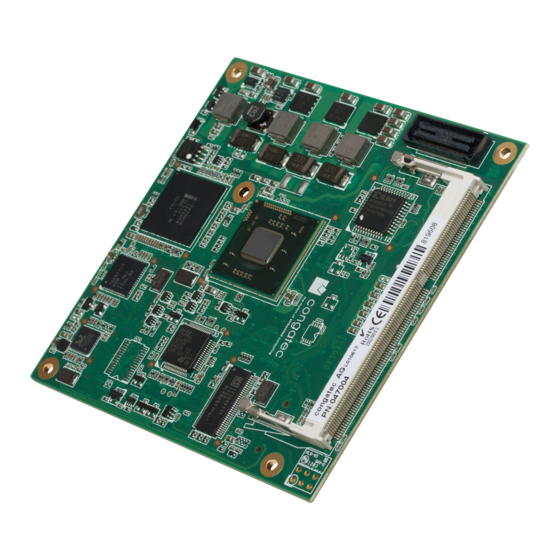
- Page 1 COM Express™ conga-TCA ® ® 2nd Generation Dual Core Intel Atom™ processor with an Intel NM10 express chipset User’s Guide Revision 1.0...
-
Page 2: Revision History
Added BIOS binary size in section 10 “Additional BIOS Features”. • Added section 10.1 “Supported Flash Devices”. • 2013.08.09 • Updated section 9 “BIOS Setup Description”. Updated section 10.1 “Supported Flash Devices”. • Official release • Copyright © 2012 congatec AG TCEDm10 2/94... - Page 3 In no event shall congatec AG be liable for any incidental, consequential, special, or exemplary damages, whether based on tort, contract or otherwise, arising out of or in connection with this user’s guide or any other information...
- Page 4 SATA Serial ATA PCI Express Graphics Platform Controller Hub PATA Parallel ATA Top of memory = max. DRAM installed T.O.M. High Definition Audio Interface N.C. Not connected Not available N.A. To be determined Copyright © 2012 congatec AG TCEDm10 4/94...
- Page 5 (c) arising from course of performance, course of dealing, or usage of trade. congatec AG shall in no event be liable to the end user for collateral or consequential damages of any kind. congatec AG shall not otherwise be liable for loss, damage or expense directly or indirectly arising from the use of the product or from any other cause.
- Page 6 Simply unplug one module and replace it with another, no redesign is necessary. 6/94 Copyright © 2012 congatec AG TCEDm10...
- Page 7 AG technicians and engineers are committed to providing the best possible technical support for our customers so that our products can be easily used and implemented. We request that you first visit our website at www.congatec.com for the latest documentation, utilities and drivers, which have been made available to assist you.
- Page 8 Intel 1.60 GHz 1.86 GHz 1.86 GHz 1.86 GHz L2 Cache 1 MByte 1 MByte 1 MByte 1 MByte SDVO DisplayPort (DP) HDMI 3.5 W 6.5 W Processor TDP 10 W 10 W Copyright © 2012 congatec AG TCEDm10 8/94...
-
Page 9: Table Of Contents
DisplayPort (DP) ..............29 1.5.2 conga-TCA Intel Atom™ N2800 Dual Core 1.86 GHz 1MB Cache Additional Features ..............30 ® congatec Board Controller (cBC) ..........30 1.5.3 conga-TCA Intel Atom™ D2550 Dual Core 1.86 GHz 1MB Cache ® Board Information ..............30 Watchdog ................. - Page 10 IO Hub Devices Submenu ............81 9.4.9.2 PCI Express Port Submenu ............. 82 9.4.10 SATA Submenu ................ 83 9.4.11 iFFS Submenu ................. 83 9.4.12 USB Submenu ................. 84 9.4.13 Super I/O Submenu ..............85 Copyright © 2012 congatec AG TCEDm10 10/94...
- Page 11 Table 30 IRQ Lines in PIC mode ............66 Table 31 IRQ Lines in APIC mode ............67 Table 32 PCI Configuration Space Map ..........68 Table 33 PCI Interrupt Routing Map ............69 Copyright © 2012 congatec AG TCEDm10 11/94...
-
Page 12: Specifications
• • 8x USB 2.0 (UHCI and EHCI) • SM Bus UEFI 2.x firmware, 4MByte serial SPI with congatec Embedded BIOS features BIOS AMI Aptio ® ACPI 3.0 compliant with battery support. Also supports Suspend to RAM (S3). Power Management Note Some of the features mentioned in the above Feature Summary are optional. -
Page 13: Supported Operating Systems
(height) carrier board connector is used then approximate overall height is 18mm. If the 8mm (height) carrier board connector is used then approximate overall height is 21mm. Heatspreader Module PCB 4.00 7.00 13.00 18.00 5.00 2.00 4.50 Carrier Board PCB Copyright © 2012 congatec AG TCEDm10 13/94... -
Page 14: Supply Voltage Standard Power
The input voltages shall rise from 10% of nominal to 90% of nominal at a minimum rise time of 250V/s. The smooth turn-on requires that, during the 10% to 90% portion of the rise time, the slope of the turn-on waveform must be positive. Copyright © 2012 congatec AG TCEDm10... -
Page 15: Power Consumption
• 100% CPU workload at approximately 100°C peak power consumption (power plan = Balanced) • Suspend to RAM. Supply power for S3 mode is 5V. Note A software tool was used to stress the CPU to maximum frequency. 15/94 Copyright © 2012 congatec AG TCEDm10... -
Page 16: Conga-Tca Intel ® Atom™ N2600 Dual Core 1.6 Ghz 1Mb Cache
100% workload approx. Suspend to Ram (S3) 5V Input 100°C CPU temp (peak) Power Power consumption (measured in Amperes/Watts) 0.57 A/6.8 W (12V) 0.83 A/9.9 W (12V) 1.03 A/12.3 W (12V) 0.1 A/0.5 W (5V) 16/94 Copyright © 2012 congatec AG TCEDm10... -
Page 17: Atom™ D2550 Dual Core 1.86 Ghz 1Mb Cache
CPU workload and not the maximum workload of the complete module. Supply power for S3 mode is 5V while all other measured modes are supplied with 12V power. Power consumption results will vary depending on the workload of other components such as graphics engine, memory, etc. Copyright © 2012 congatec AG TCEDm10 17/94... -
Page 18: Supply Voltage Battery Power
If for some reason it is not possible to use the appropriate congatec module heatspreader, then it is the responsibility of the operator to ensure that all components found on the module operate within the component manufacturer’s specified temperature range. -
Page 19: Block Diagram
® Intel NM10 ® Processor Express Chipset N2800 x2 (N2000) CG82NM10 PCH congatec x4 (D2000) N2600 GPIs/GPOs Board Controller D2550 STM32F100R8 SM Bus PCIe2USB3 DDR3-SODIMM max. 4 GByte Memory Types (up to 1066MTs) Copyright © 2012 congatec AG TCEDm10 19/94... -
Page 20: Heatspreader
When using PN: 047003 conga-TCA/D2550 and/or PN: 047004 conga-TCA/D2550 xHCI modules in conjunction with the conga-TCA/CSP-T(B) passive cooling solution, active airflow must be provided over the cooling fins. The conga-TCA/CSP-T(B) is not capable of dissipating the heat generated by these modules without an active airflow present. Copyright © 2012 congatec AG TCEDm10 20/94... -
Page 21: Heatspreader Dimensions
DIN/IS0 specifications. Caution When using the heatspreader in a high shock and/or vibration environment, congatec recommends the use of a thread-locking fluid on the heatspreader screws to ensure the above mentioned torque specification is maintained. Copyright © 2012 congatec AG... -
Page 22: Connector Subsystems Rows A, B, C, D
(optional via a x1 PCI Express Link) Gigabit Ethernet (connected via a x1 PCI Express Link) SM Bus I²C Bus Fast Mode VGA (CRT) LVDS LPC Bus Power Control/Management Fan Control top view Copyright © 2012 congatec AG TCEDm10 22/94... -
Page 23: Primary Connector Rows A And B
The GBE0_LINK# output is only active during a 100Mbit or 1Gbit connection, it is not active during a 10Mbit connection. This is a limitation of Ethernet controller since it only has 3 LED outputs, ACT#, LINK100# and LINK1000#. The GBE0_LINK# signal is a logic AND of the GBE0_LINK100# and GBE0_LINK1000# signals on the conga-TCA module. Copyright © 2012 congatec AG TCEDm10 23/94... -
Page 24: Lpc Bus
LPC Bus. 8.2.1 4.1.6 I²C Bus Fast mode The I²C bus is implemented through the congatec board controller (STMicroelectronics STM32). It provides a Fast Mode multi-master I²C Bus that has maximum I²C bandwidth. 4.1.7 PCI Express™... -
Page 25: Lcd
The conga-TCA provides various general purpose inputs and outputs for custom system design. These GPIOs are provided via Intel ® CG82NM10 (NM10) and routed to the A,B connector through the congatec Board Controller (STM32F100R8). 25/94 Copyright © 2012 congatec AG... -
Page 26: Power Control
(typically 100ms) after all carrier board power rails are up, to ensure a stable system. See screenshot below. Note The module is kept in reset as long as the PWR_OK is driven by carrier board hardware. 26/94 Copyright © 2012 congatec AG TCEDm10... - Page 27 0.8V when the 12V is applied to the module. Actively driving PWR_OK high is compliant to the COM Express specification but this can cause back driving. Therefore, congatec recommends driving the PWR_OK low to keep the module in reset and tri-state PWR_OK when the carrier board hardware is ready to boot.
-
Page 28: Power Management
25 figure 7 of the document “ATX12V Power Supply Design Guide V2.2”. 4.1.15 Power Management ACPI 3.0 compliant with battery support. Also supports Suspend to RAM (S3). Copyright © 2012 congatec AG TCEDm10 28/94... -
Page 29: Secondary Connector Rows C And D
The Intel Atom™ D2000/N2000 series processors can support a maximum ® of 2 DP ports simultaneously. See section 7.5 of this document for more information about enabling DisplayPort peripherals. Copyright © 2012 congatec AG TCEDm10 29/94... -
Page 30: Additional Features
The conga-TCA is equipped with a STMicroelectronics STM32 microcontroller. This onboard microcontroller plays an important role for most of the congatec embedded/industrial PC features. It fully isolates some of the embedded features such as system monitoring or the I²C bus from the x86 core architecture, which results in higher embedded feature performance and more reliability, even when the x86 processor is in a low power mode. -
Page 31: Power Loss Control
OEM BIOS Code With the congatec embedded BIOS it is even possible for system designers to add their own code to the BIOS POST process. Except for custom specific code, this feature can also be used to support Win XP SLP installation, Window 7 SLIC table, verb tables for HDA codecs, rare graphic modes and Super I/O controllers. -
Page 32: Congatec Battery Management Interface
EAPI (Embedded Application Programming Interface) is a programming interface defined by the PICMG that addresses this problem. With this unified API, it is now possible to run the same application on all vendor’s COMs that offer EAPI driver support. Contact congatec technical support for more information about EAPI. -
Page 33: Security Features
RSA algorithms with key lengths up to 2,048 bits as well as a real random number generator. Security sensitive applications like gaming and e-commerce will benefit also with improved authentication, integrity and confidence levels. Suspend to Ram The Suspend to RAM feature is available on the conga-TCA. Copyright © 2012 congatec AG TCEDm10 33/94... -
Page 34: Conga Tech Notes
The maximum operating temperature for Intel ® Two modes are supported by the Thermal Monitor to activate the TCC. They are called Automatic and On-Demand. No additional hardware, software, or handling routines are necessary when using Automatic Mode. Copyright © 2012 congatec AG TCEDm10 34/94... -
Page 35: Processor Performance Control
When the temperature in the thermal zone must be reduced, the operating system can decrease the power consumption of the processor by throttling the processor clock. One of the advantages of this cooling policy is that passive cooling devices (in this case the processor) do not 35/94 Copyright © 2012 congatec AG TCEDm10... - Page 36 • The two coefficients TC1 and TC2 and the sampling period TSP are hardware dependent constants. These constants are set to fixed values for the conga-TCA: • TC1= 1 • TC2= 5 • TSP= 5 seconds See section 12 of the ACPI Specification 2.0 C for more information about passive cooling. 36/94 Copyright © 2012 congatec AG TCEDm10...
-
Page 37: Acpi Suspend Modes And Resume Events
RTC Alarm Activate and configure Resume On RTC Alarm in the Power setup menu. Only available in S5. Watchdog Power Button Event Wakes unconditionally from S3-S5. Copyright © 2012 congatec AG TCEDm10 37/94... -
Page 38: Usb 2.0 Ehci Host Controller Support
UHCI #3 UHCI #2 UHCI #1 UHCI #0 (D29:F3) (D29:F2) (D29:F1) (D29:F0) Port 7 Port 6 Port 5 Port 4 Port 3 Port 2 Port 1 Port 0 Debug Enhanced Host Controller Logic Port Copyright © 2012 congatec AG TCEDm10 38/94... -
Page 39: Signal Descriptions And Pinout Tables
Signal Descriptions and Pinout Tables The following section describes the signals found on COM Express™ Type VI connectors used for congatec AG modules. The pinout of the modules complies with COM Express Type 6.0 Rev. 2.1. Table 2 describes the terminology used in this section for the Signal Description tables. The PU/PD column indicates if a COM Express™... -
Page 40: A-B Connector Signal Descriptions
High Definition Audio. ® Note Some signals have special functionality during the reset process. They may bootstrap some basic important functions of the module. For more information refer to section 7.5 of this user’s guide. Copyright © 2012 congatec AG TCEDm10 40/94... -
Page 41: Table 4 Gigabit Ethernet Signal Descriptions
The GBE0_LINK# output is only active during a 100Mbit or 1Gbit connection, it is not active during a 10Mbit connection. This is a limitation of Ethernet controller since it only has 3 LED outputs, ACT#, LINK100# and LINK1000#. The GBE0_LINK# signal is a logic AND of the GBE0_LINK100# and GBE0_LINK1000# signals on the conga-TCA module. Copyright © 2012 congatec AG TCEDm10 41/94... -
Page 42: Table 5 Serial Ata Signal Descriptions
I SATA Not supported SATA3_RX- SATA3_TX+ Serial ATA channel 3, Transmit Output differential pair. O SATA Not supported SATA3_TX- (S)ATA_ACT# A28 ATA (parallel and serial) or SAS activity indicator, active low. I/O 3.3v Copyright © 2012 congatec AG TCEDm10 42/94... -
Page 43: Table 6 Pci Express Signal Descriptions (General Purpose)
PCI Express Reference Clock output for all PCI Express A PCI Express compliant clock buffer chip must be used on the O PCIE PCIE_CLK_REF- carrier board if more than one PCI Express device is designed and PCI Express Graphics Lanes. Copyright © 2012 congatec AG TCEDm10 43/94... -
Page 44: Table 7 Expresscard Support Pins Descriptions
O 3.3V Note Some signals have special functionality during the reset process. They may bootstrap some basic important functions of the module. For more information refer to section 7.5 of this user’s guide. Copyright © 2012 congatec AG TCEDm10 44/94... -
Page 45: Table 9 Usb Signal Descriptions
Vertical sync output to VGA monitor O 3.3V DDC clock line (I²C port dedicated to identify VGA monitor capabilities) I/O OD 5V PU 2k2 3.3V VGA_I2C_CK VGA_I2C_DAT B96 I/O OD 5V PU 2k2 3.3V DDC data line. 45/94 Copyright © 2012 congatec AG TCEDm10... -
Page 46: Table 11 Lvds Signal Descriptions
I/O 3.3V Note Some signals have special functionality during the reset process. They may bootstrap some basic important functions of the module. For more information refer to section 7.5 of this user’s guide. 46/94 Copyright © 2012 congatec AG TCEDm10... -
Page 47: Table 12 Spi Bios Flash Interface Signal Descriptions
TPM. Note Some signals have special functionality during the reset process. They may bootstrap some basic important functions of the module. For more information refer to section 7.5 of this user’s guide. Copyright © 2012 congatec AG TCEDm10 47/94... -
Page 48: Table 14 General Purpose I/O Signal Descriptions
Battery low input. This signal may be driven low by external circuitry to signal that the system PU 10k 3.3VSB I 3.3VSB battery is low, or may be used to signal some other external power-management event. Copyright © 2012 congatec AG TCEDm10 48/94... -
Page 49: Table 16 General Purpose Serial Interface Signal Descriptions
A51, A57, A60, A66, All available GND connector pins shall be used and tied to Carrier Board GND plane. A70, A80, A90, A100, A110, B1, B11, B21, B31, B41, B51, B60, B70, B80, B90, B100, B110 Copyright © 2012 congatec AG TCEDm10 49/94... -
Page 50: A-B Connector Pinout
GPI3 GND (FIXED) GND (FIXED) RSVD VCC_5V_SBY SPKR RSVD VCC_5V_SBY AC/HDA_BITCLK PCIE0_CK_REF+ BIOS_DIS1# AC/HDA_SDOUT I2C_CK BIOS_DIS0# PCIE0_CK_REF- VGA_RED I2C_DAT THRMTRIP# THRM# GND (FIXED) GND (FIXED) USB6- SPI_POWER VGA_GRN USB7- USB6+ USB7+ SPI_MISO VGA_BLU 50/94 Copyright © 2012 congatec AG TCEDm10... - Page 51 A108 VCC_12V B108 VCC_12V GPI0 GPO1 A109 VCC_12V B109 VCC_12V PCIE_TX4+ PCIE_RX4+ A110 GND (FIXED) B110 GND (FIXED) Note The signals marked with an asterisk symbol (*) are not supported on the conga TCA. 51/94 Copyright © 2012 congatec AG TCEDm10...
-
Page 52: C-D Connector Signal Descriptions
USB_SSRX3- Not supported USB_SSTX3+ Additional transmit signal differential pairs for the Superspeed USB data path O Not supported USB_SSTX3- Not supported Note USB 3.0 is only supported on PN: 047004 conga-TCA/D2550 xHCI modules. 52/94 Copyright © 2012 congatec AG TCEDm10... -
Page 53: Table 21 Pci Express Signal Descriptions (X16 Graphics)
PCIE_RX[16-31] + and -. PEG_RX1+ PEG_RX1- PEG_RX2+ PEG_RX2- PEG_RX3+ PEG_RX3- PEG_RX4+ PEG_RX4- PEG_RX5+ PEG_RX5- PEG_RX6+ PEG_RX6- PEG_RX7+ PEG_RX7- PEG_RX8+ PEG_RX8- PEG_RX9+ PEG_RX9- PEG_RX10+ PEG_RX10- PEG_RX11+ PEG_RX11- PEG_RX12+ PEG_RX12- PEG_RX13+ PEG_RX13- PEG_RX14+ PEG_RX14- PEG_RX15+ C101 PEG_RX15- C102 53/94 Copyright © 2012 congatec AG TCEDm10... - Page 54 PEG_TX15- D102 PEG_LANE_RV# D54 PCI Express Graphics lane reversal input strap. Pull low on the carrier board to reverse lane Not supported order. Note PCI Express Graphics is not supported on conga-TCA modules 54/94 Copyright © 2012 congatec AG TCEDm10...
-
Page 55: Table 22 Ddi Signal Description
DDI2_CTRLCLK_AUX- is a boot strap signal (see note below). DP AUX- function if DDI2_DDC_AUX_SEL is no connect. I/O PCIE 3.3V HDMI/DVI I2C CTRLDATA if DDI2_DDC_AUX_SEL is pulled high. DDI enable strap already populated. I/O OD 3.3V 55/94 Copyright © 2012 congatec AG TCEDm10... - Page 56 DDI interface of the COM Express connector. The SDVO interface is however not supported on the conga-TCA. Refer to the HDMI and DisplayPort signal description tables in this section for information about the signals routed to the DDI interface of the COM Express connector. 56/94 Copyright © 2012 congatec AG TCEDm10...
-
Page 57: Table 23 Hdmi Signal Descriptions
Not supported Multiplexed with DDI3_PAIR0+ and DDI3_PAIR0-. TMDS3_DATA2- HDMI3_HPD HDMI/DVI Hot-plug detect. I PCIE Not supported Multiplexed with DDI3_HPD. HDMI3_CTRLCLK C Control Clock HDMI/DVI I I/O OD 3.3V Not supported Multiplexed with DDI3_CTRLCLK_AUX+ 57/94 Copyright © 2012 congatec AG TCEDm10... - Page 58 Multiplexed with DDI3_CTRLDATA_AUX- Note Some signals have special functionality during the reset process. They may bootstrap some basic important functions of the module. For more information refer to section 7.5 of this user’s guide. 58/94 Copyright © 2012 congatec AG TCEDm10...
-
Page 59: Table 24 Displayport (Dp) Signal Descriptions
Not supported DP3_LANE3- secondary data. Multiplexed with DDI3_PAIR3+ and DDI3_PAIR3-. DP3_LANE2+ Uni-directional main link for the transport of isochronous streams and O PCIE Not supported DP3_LANE2- secondary data. Multiplexed with DDI3_PAIR2+ and DDI3_PAIR2-. 59/94 Copyright © 2012 congatec AG TCEDm10... - Page 60 EDID access. Note Some signals have special functionality during the reset process. They may bootstrap some basic important functions of the module. For more information refer to section 7.5 of this user’s guide. 60/94 Copyright © 2012 congatec AG TCEDm10...
-
Page 61: Table 25 Module Type Definition Signal Description
C80, C84, C87, C90, C93, C96, C100, C103, C110, D1, D2, D5, D8, D11, D14, D21, D31, D41, D51, D60, D67, D70, D73, D76, D80, D84, D87, D90, D93, D96, D100, D103, D110 61/94 Copyright © 2012 congatec AG TCEDm10... -
Page 62: C-D Connector Pinout
DDI1_PAIR2+ DDI2_CTRLDATA_AUX- DDI1_PAIR2- PEG_RX11+ (*) PEG_TX11+ (*) PEG_RX11- (*) PEG_TX11- (*) DDI2_DDC_AUX_SEL DDI1_DDC_AUX_SEL RSVD RSVD GND (FIXED) GND (FIXED) DDI3_CTRLCLK_AUX+ (*) DDI1_PAIR3+ PEG_RX12+ (*) PEG_TX12+ (*) DDI3_CTRLDATA_AUX- (*) DDI1_PAIR3- PEG_RX12- (*) PEG_TX12- (*) 62/94 Copyright © 2012 congatec AG TCEDm10... - Page 63 D108 VCC_12V TYPE0# PEG_LANE_RV# C109 VCC_12V D109 VCC_12V PEG_RX1+ (*) PEG_TX1+ (*) GND (FIXED) D110 GND (FIXED) C110 Note The signals marked with an asterisk symbol (*) are not supported on the conga-TCA. 63/94 Copyright © 2012 congatec AG TCEDm10...
-
Page 64: Boot Strap Signals
No external DC loads or external pull-up or pull-down resistors should change the configuration of the signals listed in the above table. External resistors may override the internal strap states and cause the COM Express™ module to malfunction and/or cause irreparable damage to the module. 64/94 Copyright © 2012 congatec AG TCEDm10... -
Page 65: System Resources
On the conga-TCA, the internal PCI Bus acts as the subtractive decoding agent. All I/O cycles that are not positively decoded are forwarded to the internal PCI Bus not the LPC Bus. Only specified I/O ranges are forwarded to the LPC Bus. In the congatec Embedded BIOS the following I/O address ranges are sent to the LPC Bus: 2Eh –... -
Page 66: Interrupt Request (Irq) Lines
Parts of these ranges are not available if a Super I/O is used on the carrier board. If a Super I/O is not implemented on the carrier board, then these ranges are available for customer use. If you require additional LPC Bus resources other than those mentioned above, or more information about this subject, contact congatec technical support for assistance. Interrupt Request (IRQ) Lines... -
Page 67: Table 31 Irq Lines In Apic Mode
PIRQH, EHCI Host Controller #1, UHCI Controller #0, COMx Slot #0, COMx Slot #1, COMx Slot #2, COMx Slot #3 Note In APIC mode, the PCI bus interrupt lines are connected with IRQ 16, 17, 18 and 19. 67/94 Copyright © 2012 congatec AG TCEDm10... -
Page 68: Pci Configuration Space Map
1. The PCI Express Ports are visible only if a device is attached behind them to the PCI Express Slot on the base board. 2. This device is only present on some conga-TCA variants. 68/94 Copyright © 2012 congatec AG TCEDm10... -
Page 69: Pci Interrupt Routing Map
These interrupt lines are virtual (message based) I²C Bus There are no onboard resources connected to the I²C bus. Address 16h is reserved for congatec Battery Management solutions. SM Bus System Management (SM) bus signals are connected to the Intel CG82NM10 (NM10) PCH and the SM bus is not intended to be used by ®... -
Page 70: Bios Setup Description
POST allowing the operator to select either the boot device that should be used or an option to enter the BIOS setup program. Setup Menu and Navigation The congatec BIOS setup screen is composed of the menu bar and two main frames. The menu bar is shown below: Main Advanced... -
Page 71: Main Setup Screen
Serial Number Displays the serial number of the board. no option BC Firmware Rev. Displays the revision of the congatec board controller. no option Displays the MAC address of the onboard Ethernet controller. MAC Address no option Displays the number of boot-ups. (max. 16777215). -
Page 72: Intel Rc Version Submenu
Main Advanced Boot Security Save & Exit Graphics Watchdog Hardware Monitoring ACPI RTC Wake Memory Chipset SATA iFFS Super IO Console Redirection Network Stack Copyright © 2012 congatec AG TCEDm10 72/94... -
Page 73: Graphics Submenu
VGA 640x480 1x18 (013h) Auto detection is performed by reading an EDID data set via the video I²C bus. The number in brackets specifies the congatec internal number of the respective panel data set. WVGA 800x480 1x24 (01Bh) Note: Customized EDID™ utilizes an OEM defined EDID™ data set stored in the BIOS flash device. -
Page 74: Watchdog Submenu
Selects the type of event that will be generated when timeout 1 is reached. For more information about ACPI Event, see note below. Reset Power Button Event 2 Selects the type of event that will be generated when timeout 2 is reached. Disabled ACPI Event Reset Power Button Copyright © 2012 congatec AG TCEDm10 74/94... - Page 75 Note In ACPI mode it is not possible for a “Watchdog ACPI Event” handler to directly restart or shutdown the OS. For this reason, the congatec BIOS will do one of the following: For Shutdown: An over temperature notification is executed. This causes the OS to shut down in an orderly fashion.
-
Page 76: Hardware Monitoring Submenu
If enabled, the fan will always run at least at the selected minimum speed, even if the control temperature is below the Disabled Enabled fan control start temperature. This is to ensure a minimum air flow all the time. Only visible if Automatic Fan Speed Speed Control is enabled. 76/94 Copyright © 2012 congatec AG TCEDm10... -
Page 77: Pci Submenu
IRQ10, IRQ11 Reserve Legacy Interrupt 2 Same as Reserve Same as Reserve Legacy Interrupt 1 Legacy Interrupt 1 ►PIRQ Routing & IRQ submenu Manual PIRQ routing and interrupt reservation for legacy devices. Reservation Copyright © 2012 congatec AG TCEDm10 77/94... -
Page 78: Pirq Routing & Irq Reservation Submenu
Specifies the temperature threshold at which the ACPI aware OS starts or stops CPU clock throttling. This method of 95, 100, 105, 110, 115, 120, Passive cooling is not recommended. The preferred method of passive cooling is the setting of the TCC active offset 125 °C, Disabled in CPU Configuration menu. Copyright © 2012 congatec AG TCEDm10 78/94... -
Page 79: Rtc Wake Settings Submenu
Disabled Allows an automatic return to a previous C3/C4 State C-State POPDOWN Enabled Disabled Allows to take the system from C3/C4 state to C2 state according to bus master request. C-State POPUP Enabled Copyright © 2012 congatec AG TCEDm10 79/94... -
Page 80: Memory Submenu
Enabled Disabled Enable or disable High Precision Event Timer High Precision Timer Enabled SLP_S4 Assertion Width 1-2 Second Selects the minimum assertion width of the SLP_S4 Signal. 2-3 Second 3-4 Second 4-5 Second Copyright © 2012 congatec AG TCEDm10 80/94... -
Page 81: Io Hub Devices Submenu
Enable or disable USB 2.0 (EHCI) Support. USB 2.0 (EHCI) Support Enabled Disabled Enable or disable the SMBus Controller. SMBus Controller Enabled SIRQ Logic Disabled Enables Serial IRQ Logic. Enabled SIRQ Mode Quiet Controls Serial IRQ Mode. Continous Copyright © 2012 congatec AG TCEDm10 81/94... -
Page 82: Pci Express Port Submenu
Extra Bus Reserved (0-7) for bridges behind this Root Bridge. Default value is 0 Reserved Memory [1-20] Reserved Memory and Prefetchable Memory (1-20MB) Range for this Root Bridge. Default Value is 1MB. Reserved I/O 4K,8K,2K,16K,20K Reserved I/O (4K/8K/12K/16K/20K) Range for this Root Bridge. Copyright © 2012 congatec AG TCEDm10 82/94... -
Page 83: Sata Submenu
Disabled SMART Self Test Run SMART self Test on all Hard Disk during POST. Disabled Enabled 9.4.11 iFFS Submenu Feature Options Description IFFS Support Indicates support for Intel Fast Flash Standby. Disabled Enabled Copyright © 2012 congatec AG TCEDm10 83/94... -
Page 84: Usb Submenu
Forced FDD allows a hard disk image to be connected as a floppy image. Works only for drives formatted with FAT12, FAT16 or FAT32. Hard disk allows the device to be emulated as hard disk. CDROM assumes the CD-ROM is formatted as bootable media, specified by the ‘El Torito’ Format Specification. Copyright © 2012 congatec AG TCEDm10 84/94... -
Page 85: Super I/O Submenu
►Console Redirection Settings submenu Opens console redirection configuration sub menu. Serial Port for Out-of-Band management/Windows Emergency management Services (EMS) Console Redirection Enable Console Redirection Settings setup Node for EMS. Disabled Enabled ►Console Redirection Settings submenu 85/94 Copyright © 2012 congatec AG TCEDm10... -
Page 86: Console Redirection Settings Submenu
VT100+ VT-UTF8 ANSI 9600, 19200, 38400, Select baud rate. Baud rate 57600, 115200 Flow Control Select flow control. None Hardware RTS/CTS Data Bits no option Parity None no option Stop Bits no option 86/94 Copyright © 2012 congatec AG TCEDm10... -
Page 87: Network Stack Submenu
Enabled If Enabled, a congatec OEM logo or a black screen shows during POST. The black screen shows only if the OEM logo is not found. If Auto, a congatec OEM boot logo loads if present. If no OEM boot logo is found, the system shows POST strings and congatec Auto boot logo. - Page 88 Note 1. The term ‘AC power loss’ stands for the state when the module looses the standby voltage on the 5V_SB pins. On congatec modules, the standby voltage is continuously monitored after the system is turned off. If within 30 seconds the standby voltage is no longer detected, then this is considered an AC power loss condition.
-
Page 89: Csm & Option Rom Parameters Submenu
Set display mode for option ROMs. Force BIOS Keep Current INT19 Trap Response BIOS reaction on INT19 trapping by Option ROM: IMMEDIATE - execute the trap right away; Immediate POSTPONED - execute the trap during legacy boot. Postponed Copyright © 2012 congatec AG TCEDm10 89/94... -
Page 90: Security Setup
Both user and master password can be set independently however the drive will only lock if a user password is installed. Copyright © 2012 congatec AG TCEDm10... -
Page 91: Save & Exit Menu
Save changes made so far to any of the setup options. Stay in setup menu. Discard Changes Discard changes made so far to any of the setup options. Stay in setup menu. Restore Defaults Restore default values for all the setup options. Copyright © 2012 congatec AG TCEDm10 91/94... -
Page 92: Additional Bios Features
The BIOS displays a message during POST and on the main setup screen identifying the BIOS project name and a revision code. The initial production BIOS is identified as TCEDR1xx where TCED is the congatec internal project name, R is the identifier for a BIOS ROM file, 1 is the so called feature number and xx is the major and minor revision number. -
Page 93: Hard Disk Security Features
BIOS disables the ATA security features at the end of POST to prevent their misuse. Without this protection it would be possible for viruses or malicious programs to set a password on a drive thereby blocking the user from accessing the data. Copyright © 2012 congatec AG TCEDm10... -
Page 94: Industry Specifications
Industry Specifications The list below provides links to industry specifications that apply to congatec AG modules. Specification Link Low Pin Count Interface Specification, Revision 1.0 (LPC) http://developer.intel.com/design/chipsets/industry/lpc.htm Universal Serial Bus (USB) Specification, Revision 2.0 http://www.usb.org/home PCI Specification, Revision 2.3 http://www.pcisig.com/specifications Serial ATA Specification, Revision 3.0...
Need help?
Do you have a question about the conga-TCA 047001 and is the answer not in the manual?
Questions and answers