
Related Manuals for Congatec conga-PA5 Pico-ITX SBC


Summary of Contents for Congatec conga-PA5 Pico-ITX SBC
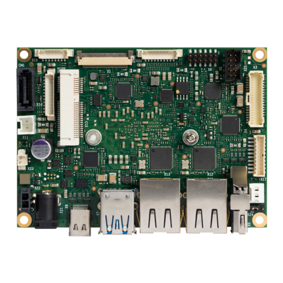
- Page 1 Pico-ITX SBC Detailed Description Of The congatec Pico-ITX Based On 5 Generation Intel® Atom®, Celeron® and Pentium® User's Guide Revision 1.12...
- Page 2 Updated accessories in tables 3, 4, and 5 and combined them under section 1.2.3 "Optional accessories" • Removed table with cooling solutions from section 4 "Cooling solutions" and linked to table 3 instead Copyright © 2017 congatec GmbH PA50m112 2/48...
- Page 3 • Moved section 6.2.4 "CPU Fan Header" to section 6.2.1.1 and added PWM explanation 1.12 2021.07.02 • Updated congatec AG to congatec GmbH throughout the document • Added Software License Information • Updated section 6.4 "congatec Battery Management Interface" Copyright © 2017 congatec GmbH...
- Page 4 DECLINE ALL LIABILITY for damages, direct or indirect, that result from the use of this software. OEM/ CGUTL BIOS BIOS/UEFI modified by customer via the congatec System Utility (CGUTL) is subject to the same license as the BIOS/UEFI it is based on. You https://www.congatec.com/en/licenses/...
- Page 5 All congatec GmbH products are created from lead-free components and are completely RoHS compliant. Electrostatic Sensitive Device All congatec GmbH products are electrostatic sensitive devices. They are enclosed in static shielding bags, and shipped enclosed in secondary packaging (protective packaging). The secondary packaging does not provide electrostatic protection.
- Page 6 (c) arising from course of performance, course of dealing, or usage of trade. congatec GmbH shall in no event be liable to the end user for collateral or consequential damages of any kind. congatec shall not otherwise be liable for loss, damage or expense directly or indirectly arising from the use of the product or from any other cause.
- Page 7 Trademarks Product names, logos, brands, and other trademarks featured or referred to within this user’s guide, or the congatec website, are the property of their respective trademark holders. These trademark holders are not affiliated with congatec GmbH, our products, or our website.
-
Page 8: Table Of Contents
Block Diagram ................20 6.1.3 GPIOs ..................41 6.1.4 Micro-SD Card Slot ..............42 Cooling Solutions ..............21 congatec Board Controller (cBC) ..........42 6.2.1 Fan Control ................42 CSP Dimensions ..............22 6.2.1.1 CPU Fan Header ..............42 HSP Dimensions ............... 24 6.2.2... - Page 9 BIOS Setup Description ............47 Navigating the BIOS Setup Menu ........... 47 BIOS Versions................47 Updating the BIOS ..............48 Supported Flash Device ............48 Copyright © 2017 congatec GmbH PA50m112 9/48...
- Page 10 X10 Pinout Description ............38 Table 24 X18 Pinout Description ............39 Table 25 X19 Pinout Description ............40 Table 26 X20 Pinout Description ............41 Table 27 X17 Pinout Description ............42 Copyright © 2017 congatec GmbH PA50m112 10/48...
- Page 11 Low-Voltage Differential Signaling Display Data Channel is an I²C bus interface between a display and a graphics adapter. Part Number - the part number for placing orders. Not connected Not available To be determined Copyright © 2017 congatec GmbH PA50m112 11/48...
-
Page 12: Introduction
Additionally, the SBC supports onboard LPDDR4 memory up to 2400 MT/s, maximum system memory capacity of 8 GB, multiple I/O interfaces, up to three independent displays and various congatec embedded features. With smaller board size and lower height keep-out zones, the conga-PA5 SBC provides manufacturers and system designers with the opportunity to design compact systems for space restricted areas. -
Page 13: Options Information
2 MB Burst Frequency 2.3 GHz Onboard Memory 4 GB 2133 MT/s Processor Graphics Intel HD Graphics 500 ® Graphics Base / Burst 250/750 MHz LVDS Single/Dual 18/24-bit DP++ Processor TDP (Max) 10 W Copyright © 2017 congatec GmbH PA50m112 13/48... -
Page 14: Table 2 Conga-Pa5 Industrial Variants
® HD Graphics 500 Graphics Base / Burst 500/650 MHz 400/600 MHz 400/550 MHz LVDS Single/Dual 18/24-bit Single/Dual 18/24-bit Single/Dual 18/24-bit DP++ DP++ DP++ Processor TDP (Max) 12 W 9.5 W 6.5 W Copyright © 2017 congatec GmbH PA50m112 14/48... -
Page 15: Optional Accessories
14000172 Internal power cable for industrial versions of conga-PA5, length 150 mm Table 5 Power Supplies Article Description Power Supply 60W 10000470 PSU, 60W, 12V / 5A, Plug 5.5x2.5mm / 10mm length Copyright © 2017 congatec GmbH PA50m112 15/48... -
Page 16: Specification
Thermal and voltage monitoring, RTC Battery, congatec standard BIOS BIOS AMI Aptio ® UEFI 5.x firmware, 8 MB SPI flash with congatec embedded BIOS features. Power ACPI 4.0 compliant with battery support. Also supports Suspend to RAM (S3). Ultra low standby power consumption. -
Page 17: Supported Operating Systems
The power consumption values were measured with the following setup: • conga-PA5 • conga-PA5 cooling solution • Microsoft ® Windows ® 10 (64-bit) Note The CPU was stressed to its maximum workload with the Intel Thermal Analysis Tool ® Copyright © 2017 congatec GmbH PA50m112 17/48... -
Page 18: Table 7 Measurement Description
® ® 048112 4 GB PA50R019 Windows Atom x5-E3930 1.3/1.8 0.14 0.95 1.06 0.04 0.04 ® ® Note With fast input voltage rise time, the inrush current may exceed the measured peak current. Copyright © 2017 congatec GmbH PA50m112 18/48... -
Page 19: Supply Voltage Battery Power
3. Consider also the self-discharge of the battery when calculating the lifetime of the CMOS battery. For more information, refer to application note AN9_RTC_Battery_Lifetime.pdf on congatec GmbH website at www.congatec.com/support/application-notes. 4. We recommend to always have a CMOS battery present when operating the conga-PA5. -
Page 20: Block Diagram
PCIe SD Card PCIe Intel I211* I²C Ethernet SATA USB 2.0 USB 3.0 eMMC GPIO *I210IT for industrial temperature Watchdog DP++ DP++ Buttons +12V SATA Power +12V +3V Battery External I/O Internal I/O Copyright © 2017 congatec GmbH PA50m112 20/48... -
Page 21: Cooling Solutions
1. We recommend a maximum torque of 0.3 Nm for the mounting screws. 2. The gap pad material used on congatec heatspreaders may contain silicon oil that can seep out over time depending on the environmental conditions it is subjected to. For more information about this subject, contact your local congatec sales representative and request the gap pad material manufacturer’s specification. -
Page 22: Csp Dimensions
Mount the cooling solution in the correct orientation—the connectors of the conga-PA5 must match the connector names written on the side of the cooling solution. Otherwise, the cooling solution can cause a short on the conga-PA5. Copyright © 2017 congatec GmbH PA50m112... - Page 23 Mount the cooling solution in the correct orientation—the connectors of the conga-PA5 must match the connector names written on the side of the cooling solution. Otherwise, the cooling solution can cause a short on the conga-PA5. Copyright © 2017 congatec GmbH PA50m112...
-
Page 24: Hsp Dimensions
Mount the cooling solution in the correct orientation—the connectors of the conga-PA5 must match the connector names written on the side of the cooling solution. Otherwise, the cooling solution can cause a short on the conga-PA5. Copyright © 2017 congatec GmbH PA50m112... - Page 25 Mount the cooling solution in the correct orientation—the connectors of the conga-PA5 must match the connector names written on the side of the cooling solution. Otherwise, the cooling solution can cause a short on the conga-PA5. Copyright © 2017 congatec GmbH PA50m112...
-
Page 26: Connector Description
The commercial conga-PA5 variants provide a DC power jack (X21), protected against short transient overvoltage and ESD. Optionally, the industrial conga-PA5 variants can also provide a DC power jack. Optionally, congatec can also assemble a DC power jack with locking mechanism, including screw type connectors. -
Page 27: Usb Type-C™ Port
X23: 2x1 pins, 1.25 mm pitch (Molex 53398-0271); Possible Mating Connector: Molex 15134-0200 Warning Danger of explosion if battery is incorrectly replaced. Replace only with same or equivalent type recommended by the manufacturer. Dispose of used batteries according to the manufacturer’s instructions. Copyright © 2017 congatec GmbH PA50m112 27/48... -
Page 28: High Definition Audio Header
Line Out L1+ HP_JD Headphone Jack Detection +5V Power Supply (for S/PDIF optical transmitter) Digital Ground for S/PDIF S/PDIF S/PDIF Output (3.3V) S/PDIF Input (3.3V) Connector Type X6: 6x2 pins, 2.0 mm pitch, box header Copyright © 2017 congatec GmbH PA50m112 28/48... -
Page 29: Usb Connectors
The conga-PA5 provides one USB Type-C™ port (X9). It supports Power Delivery (up to 5V @ 3A) and DisplayPort Alternate Mode. Connector Type X9: USB Type-C™ port Caution The maximum cable length of a USB 2.0 device connected to any port shall not exceed 3 meters in order to comply to EN 55024:2010. Copyright © 2017 congatec GmbH PA50m112 29/48... -
Page 30: Usb 2.0 Header
100 Mbps link speed Steady On Link established, no activity detected Orange 1000 Mbps link speed Blinking Link established, activity detected Connector Type X12, X13: 8-pin RJ45 connector with Gigabit magnetic and LEDs Copyright © 2017 congatec GmbH PA50m112 30/48... -
Page 31: Sata Connectors
Connector Type X11: 2x1 pins, 2.50 mm pitch (Molex 53375-0210); Possible Mating Connector: Molex 51103-0200 5.5.3 mSATA Card Slot The mSATA card slot is described in section 5.9 "mPCIe / mSATA Card Slot". Copyright © 2017 congatec GmbH PA50m112 31/48... -
Page 32: Display Interfaces
The conga-PA5 supports up to three displays via one DP++ port, one DP over USB Type-C™ port, and one LVDS header. 5.6.1 DP++ Port The conga-PA5 provides one DP++ port (X5). The maximum supported resolution is 4096 x 2160 @60 Hz (DP 1.2). Connector Type X5: 20 pins, DP++ port Copyright © 2017 congatec GmbH PA50m112 32/48... -
Page 33: Lvds/Edp Header
X3: 40 pins, 1.00 mm pitch (Molex 501190-4017); Possible Mating Connector: Molex 501189-4010 Note * For a single channel LVDS panel, use the ODD pins. congatec offers an LVDS cable for 17" AUO Optronics G170EG01 V.1 panel only (see section Table 4 "Cables"). Copyright © 2017 congatec GmbH PA50m112... -
Page 34: Backlight Power Header
The conga-PA5 supports 3.3 V and 5 V LVDS panels. Set the panel voltage (pin 35, 36, 38) with jumper X24. Table 20 X24 Pinout Description Signal Name 1 - 2 3.3V 2 - 3 Connector Type X24: 3x1-pin, 2.00 mm pitch Copyright © 2017 congatec GmbH PA50m112 34/48... -
Page 35: Com Headers
If termination is required, a 120Ohm termination must be added externally across pin 4 (RX+) and 5 (RX-). Note congatec offers adapter cables for the COM ports (see section 1.2.3 “Optional Cables) with embedded termination (for RS422 / RS485) and without embedded termination (for RS232). -
Page 36: Mipi Csi-2 (Camera)
Camera 0 Control Interface, DATA CAM0_ENA# Camera 0 Enable (low active) MCLK Master Clock. May be used to drive camera's internal PLL (19.2MHz or 25MHz) CAM1_ENA# Camera 1 Enable (low active) CAM1_I2C_CLK Camera 1 Control Interface, CLK Copyright © 2017 congatec GmbH PA50m112 36/48... - Page 37 GPIO for Camera 1 Connector Type X1: 36 pins, 0.5mm pitch (Hirose FH12A Series); Possible Mating Connector: I-PEX FAW-1223-T1 Note The MIPI interface fuse limits the power budget by 750 mA hold current. Copyright © 2017 congatec GmbH PA50m112 37/48...
-
Page 38: Mpcie / Msata Card Slot
Pin 43 of mPCIe cards must be connected to ground. +1.5V Pin 43 of mSATA cards must NOT be connected to ground. N.C. +3.3V An mPCIe extender should be used for mPCIe half-size cards. Connector Type X10: mPCIe / mSATA card slot Copyright © 2017 congatec GmbH PA50m112 38/48... -
Page 39: Additional Features
1. The LEDs on the conga-PA5 are supplied by +3.3 V with 330Ohm series resistors. You can connect X18 pins directly to the LED terminals. 2. The buttons are edge triggered with 16 ms debouncing and can be directly connected to a tactile switch or OC output. Copyright © 2017 congatec GmbH PA50m112... -
Page 40: I2C And Watchdog
The signals are 3.3V compatible. A fuse limits the 3.3V power budget of connector X19 (pin 2) and X20 (pin 10) to a total of 500 mA hold current. LED_WLAN# shall be connected to the LED's cathode. A series resistor is present on conga-PA5. Copyright © 2017 congatec GmbH PA50m112... -
Page 41: Gpios
2. The GbE + cBC UART option requires a customized BIOS. The cBC UART is not fully legacy compatible, only supports TTL, and requires a a special driver to work under Windows . For more information, contact congatec technical support. ®... -
Page 42: Micro-Sd Card Slot
The conga-PA5 is equipped with a Texas Instruments Tiva™ TM4E1231H6ZRBI microcontroller. This onboard microcontroller plays an important role for most of the congatec BIOS features. The cBC fully isolates some of the embedded features such as system monitoring, I²C bus from the x86 core architecture. -
Page 43: Power Loss Control
OEM BIOS Customization The conga-PA5 is equipped with congatec Embedded BIOS, which is based on American Megatrends Inc. Aptio UEFI firmware. The congatec Embedded BIOS allows system designers to modify the BIOS. For more information about customizing the congatec Embedded BIOS, refer to the congatec System Utility user’s guide CGUTLm1x.pdf and can be found on the congatec website or contact technical support. -
Page 44: Oem Post Logo
OEM POST Logo This feature allows system designers to replace the congatec POST logo displayed in the upper left corner of the screen during BIOS POST with their own BIOS POST logo. Use the congatec system utility CGUTIL 1.5.4 or later to replace/add the OEM POST logo. -
Page 45: Api Support (Cgos)
The architecture of the CGOS API driver provides the ability to write application software that runs unmodified on all congatec CPU modules. All the hardware related code is contained within the congatec embedded BIOS on the module. See section 1.1 of the CGOS API software developers guide, which is available on the congatec website. -
Page 46: Mechanical Drawing
Mechanical Drawing 30.6 30.6 Copyright © 2017 congatec GmbH PA50m112 46/48... - Page 47 If you do not have access to the restricted area of the congatec website, contact your local congatec sales representative. Navigating the BIOS Setup Menu The BIOS setup menu shows the features and options supported in the congatec BIOS. To access and navigate the BIOS setup menu, press the <DEL> or <F2> key during POST.
- Page 48 BIOS updates are recommended to correct platform issues or enhance the feature set of the SBC. The conga-PA5 features a congatec/AMI AptioEFI firmware on an onboard flash ROM chip. You can update the firmware with the congatec System Utility. The utility has five versions—...
Need help?
Do you have a question about the conga-PA5 Pico-ITX SBC and is the answer not in the manual?
Questions and answers