
Related Manuals for Congatec COM Express conga-TC87


Summary of Contents for Congatec COM Express conga-TC87
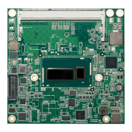
- Page 1 COM Express™ conga-TC87 ® ® 4th Generation Intel Core™ i7, i5, i3 and Mobile Intel Celeron Single Chip Ultra Low TDP Processors User’s Guide Revision 1.2 Copyright © 2013 congatec AG TU87m12 1/114...
-
Page 2: Revision History
Updated section 2.5 “Power Consumption”. • Updated section 3 “Block Diagram”. • Corrected the name of the congatec board controller in section 5.1.6 “I2C Bus Fast Mode”. • Corrected pins D63 and D64 in section 8.4 “C-D Connector Pinout”. •... - Page 3 In no event shall congatec AG be liable for any incidental, consequential, special, or exemplary damages, whether based on tort, contract or otherwise, arising out of or in connection with this user’s guide or any other information...
- Page 4 PCI Express SATA Serial ATA PCI Express Graphics Platform Controller Hub Embedded DisplayPort T.O.M. Top of memory = max. DRAM installed High Definition Audio N.C. Not connected N.A. Not available To be determined Copyright © 2013 congatec AG TU87m12 4/114...
- Page 5 (c) arising from course of performance, course of dealing, or usage of trade. congatec AG shall in no event be liable to the end user for collateral or consequential damages of any kind. congatec shall not otherwise be liable for loss, damage or expense directly or indirectly arising from the use of the product or from any other cause.
- Page 6 AG technicians and engineers are committed to providing the best possible technical support for our customers so that our products can be easily used and implemented. We request that you first visit our website at www.congatec.com for the latest documentation, utilities and drivers, which have been made available to assist you.
-
Page 7: Table Of Contents
USB 3.0 ..................36 2.5.6 Intel ® Core™ i3-4010U 1.7 GHz Dual Core™ 3MB Cache (VGA) Additional Features ..............37 congatec Board Controller (cBC) ..........37 2.5.7 Intel ® Celeron ® 2980U 1.6 GHz Dual Core™ 2MB Cache (VGA) 19 Board Information .............. - Page 8 Watchdog Submenu..............80 12.1 Supported Flash Devices ............113 11.4.3 Module Serial Ports Submenu ..........82 12.2 Updating the BIOS ..............113 11.4.4 Hardware Health Monitoring Submenu ........82 Industry Specifications ............114 Copyright © 2013 congatec AG TU87m12 8/114...
- Page 9 Power and GND Signal Descriptions ........68 Table 29 Connector C-D Pinout .............. 69 Table 30 Boot Strap Signal Descriptions ..........71 Table 31 PCI Configuration Space Map ..........73 Table 32 PCI Interrupt Routing Map ............74 Copyright © 2013 congatec AG TU87m12 9/114...
-
Page 10: Introduction
Most importantly, COM Express™ modules are scalable, which means once an application has been created there is the ability to diversify the product range through the use Copyright © 2013 congatec AG TU87m12... - Page 11 ® HD graphics 4400 (GT2) Intel ® HD graphics (GT2) Graphics Max. Dynamic Freq 1.1 GHz 1.0 GHz 1.0 GHz LVDS DisplayPort (DP) HDMI Processor TDP (Max) 15 W 15 W 15 W Copyright © 2013 congatec AG TU87m12 11/114...
-
Page 12: Specifications
SM Bus • 2x USB 3.0 (XHCI) • • GPIOs UEFI 2.x firmware, 8/16 MByte serial SPI with congatec Embedded BIOS features. ® BIOS AMI Aptio Power Management • ACPI 4.0 compliant with battery support. Also supports Suspend to RAM (S3) and Intel AMT 9.5. -
Page 13: Supported Operating Systems
(height) carrier board connector is used, then approximate overall height is 18mm. If the 8mm (height) carrier board connector is used, then approximate overall height is 21mm. Heatspreader Module PCB 4.00 13.00 7.00 18.00 5.00 2.00 4.50 Carrier Board PCB Copyright © 2013 congatec AG TU87m12 13/114... -
Page 14: Supply Voltage Standard Power
The input voltages shall rise from 10% of nominal to 90% of nominal at a minimum slope of 250V/s. The smooth turn-on requires that, during the 10% to 90% portion of the rise time, the slope of the turn-on waveform must be positive. Copyright © 2013 congatec AG TU87m12... -
Page 15: Power Consumption
• 100% CPU workload at approximately 100°C peak power consumption (power plan = Balanced) • Suspend to RAM. Supply power for S3 mode is 5V. Note A software tool was used to stress the CPU to Max Turbo Frequency. Copyright © 2013 congatec AG TU87m12 15/114... -
Page 16: Intel ® Core™ I7-4650U 1.7 Ghz Dual Core™ 4Mb Cache
(turbo mode disabled) (turbo mode enabled) 100% CPU and GPU workload 1.53 A/18.4 W (12V) 100% CPU and GPU workload (turbo mode disabled) (turbo mode enabled) Peak Power Consumption 1.95 A/23.4 W (12V) Copyright © 2013 congatec AG TU87m12 16/114... -
Page 17: Intel ® Core™ I3-4010U 1.7 Ghz Dual Core™ 3Mb Cache
Suspend to Ram (S3) 5V Input Power 100% workload 100% Workload (turbo mode disabled) (turbo mode enabled) 100% CPU and GPU workload 100% CPU and GPU workload (turbo mode disabled) (turbo mode enabled) Peak Power Consumption Copyright © 2013 congatec AG TU87m12 17/114... -
Page 18: Intel Core™ I5-4300U 1.9 Ghz Dual Core™ 3Mb Cache (Vga)
Suspend to Ram (S3) 5V Input Power 100% workload 100% Workload (turbo mode disabled) (turbo mode enabled) 100% CPU and GPU workload 100% CPU and GPU workload (turbo mode disabled) (turbo mode enabled) Peak Power Consumption Copyright © 2013 congatec AG TU87m12 18/114... -
Page 19: Supply Voltage Battery Power
PM_PCH_PWROK signal on revision C.x and earlier is not terminated to ground. This issue will be corrected with conga-TC87 hardware revisions D.x and later. Contact congatec technical support department for more information about this topic. -
Page 20: Environmental Specifications
If for some reason it is not possible to use the appropriate congatec module heatspreader, then it is the responsibility of the operator to ensure that all components found on the module operate within the component manufacturer’s specified temperature range. -
Page 21: Block Diagram
PCIe LPC Bus GPIOs SATA Port 2 SATA Port 3 congatec System (TX BC) SATA USB 2.0 USB 3.0 LPC Bus congatec custom Management Controller SM Bus I2C Bus GPIOs LID#/SLEEP# FAN control Copyright © 2013 congatec AG TU87m12 21/114... -
Page 22: Heatspreader
The combination of the two threads may be staggered, which could lead to stripping or cross-threading of the threads in either the standoffs of the heatspreader or carrier board. Copyright © 2013 congatec AG TU87m12... -
Page 23: Heatspreader Dimensions
DIN/IS0 specifications. Caution When using the heatspreader in a high shock and/or vibration environment, congatec recommends the use of a thread-locking fluid on the heatspreader screws to ensure the above mentioned torque specification is maintained. Copyright © 2013 congatec AG... -
Page 24: Onboard Temperature Sensors
The CPU temperature sensor (T00) is located in the CPU (U1). This sensor measures the CPU temperature and is defined in CGOS API as CGOS_TEMP_CPU. The board temperature sensor (T01) is located in the congatec Board Controller (cBC) . This sensor measures the board temperature and is defined in CGOS API as CGOS_TEMP_BOARD. - Page 25 The DRAM sensor location is shown below: Optional DRAM sensor location (Build-Time Option) Note The DRAM sensor is not populated on conga-TC87 standard variants. The sensor is only available as a build time option. Copyright © 2013 congatec AG TU87m12 25/114...
-
Page 26: Connector Subsystems Rows A, B, C, D
2x DisplayPort (DP) I²C Bus Fast Mode (Routed to DDI interface at LVDS/eDP connector) SM Bus 1x VGA (optional) (supported only on rev. C.x and GPIOs later) Power Control Power Management Fan Control top view Copyright © 2013 congatec AG TU87m12 26/114... -
Page 27: Primary Connector Rows A And B
10/100/1000 BaseT RJ45 connector with integrated or external isolation magnetics on the carrier board. Note The GBE0_LINK# output is only active during a 100Mbit or 1Gbit connection. It is not active during a 10Mbit connection. This is a limitation Copyright © 2013 congatec AG TU87m12 27/114... -
Page 28: Lpc Bus
ULP feature is enabled by default and cannot be disabled. In newer driver version, this feature can be disabled. To have the correct LED status, congatec recommends that you use the latest i218 device driver provided on the website and additionally disable the ULP mode. -
Page 29: Expresscard
The conga-TC87 offers two UART interfaces via two UART controllers integrated in the congatec Board Controller. These controllers support up to 1MBit/s and can operate in low-speed, full-speed and high-speed modes. The UART interfaces are routed to the AB connector and require congatec driver to function.. -
Page 30: Power Control
A sample screenshot is shown below: Note The module is kept in reset as long as the PWR_OK is driven by carrier board hardware. Copyright © 2013 congatec AG TU87m12 30/114... - Page 31 0.8V when the 12V is applied to the module. Actively driving PWR_OK high is compliant to the COM Express specification but this can cause back driving. Therefore, congatec recommends driving the PWR_OK low to keep the module in reset and tri-state PWR_OK when the carrier board hardware is ready to boot.
- Page 32 For more information about this issue visit www.formfactors.org and view page 25 figure 7 of the document “ATX12V Power Supply Design Guide V2.2”. Copyright © 2013 congatec AG TU87m12...
-
Page 33: Power Management
Deep Sx. The Deep Sx on resumption, puts system back into the state it is entered from. In other words, if Deep Sx state was entered from S3 state, then the resume path will place system back into S3. Copyright © 2013 congatec AG TU87m12... -
Page 34: Secondary Connector Rows C And D
1920x1200 /3200x2000 @60Hz DP/VGA* LVDS/eDP 3200x2000 @60Hz 3200x2000 @60Hz /1920x1200 1920x1200 /3200x2000 @60Hz HDMI/VGA* LVDS/eDP 3200x2000 @60Hz 4096x2304 @24Hz /1920x1200 1920x1200 /3200x2000 @60Hz * For rev. C.x and later variants equipped with optional VGA interface Copyright © 2013 congatec AG TU87m12 34/114... -
Page 35: Hdmi
The DisplayPort specification is a VESA standard aimed at consolidating internal and external connection methods to reduce device complexity, supporting key cross industry applications, and providing performance scalability to enable the next generation of displays. See section 9.5 of this document for more information about enabling DisplayPort peripherals. Copyright © 2013 congatec AG TU87m12 35/114... -
Page 36: Usb 3.0
8 Series PCH-LP integrated in the MCP. The host controller allows data transfers of up to 5 Gb/s and supports SuperSpeed, high- speed, full-speed and low-speed traffic. Note The xHCI controller supports USB 3.0 debugging. Copyright © 2013 congatec AG TU87m12 36/114... -
Page 37: Additional Features
I²C bus from the x86 core architecture, which results in higher embedded feature performance and more reliability, even when the x86 processor is in a low power mode. It also ensures that the congatec embedded feature set is fully compatible amongst all congatec modules. -
Page 38: Embedded Bios
OEM BIOS Code With the congatec embedded BIOS it is even possible for system designers to add their own code to the BIOS POST process. Except for custom specific code, this feature can also be used to support Win XP SLP installation, Window 7 SLIC table, verb tables for HDA codecs, rare graphic modes and Super I/O controllers. -
Page 39: Congatec Battery Management Interface
EAPI (Embedded Application Programming Interface) is a programming interface defined by the PICMG that addresses this problem. With this unified API it is now possible to run the same application on all vendor’s COMs that offer EAPI driver support. Contact congatec technical support for more information about EAPI. -
Page 40: Security Features
RSA algorithms with key lengths up to 2,048 bits as well as a real random number generator. Security sensitive applications like gaming and e-commerce will benefit also with improved authentication, integrity and confidence levels. Suspend to Ram The Suspend to RAM feature is available on the conga-TC87. Copyright © 2013 congatec AG TU87m12 40/114... -
Page 41: Conga Tech Notes
It allows configuration of a computer systems with the advantage of having HDDs for maximum storage capacity with system performance at or near SSD performance levels. Note This feature requires an Intel® Core Processor Copyright © 2013 congatec AG TU87m12 41/114... -
Page 42: Intel ® Rapid Start Technology
Only conga-TC87 module variants that feature the Core™ i7 and i5 processors support Intel ® Turbo Boost 2 Technology. Refer to the power consumption tables in section 2.5 of this document for information about the maximum turbo frequency available for each variant of the conga-TC87. Copyright © 2013 congatec AG TU87m12 42/114... -
Page 43: Thermal Monitor And Catastrophic Thermal Protection
The Windows family of operating systems links its processor performance control policy to the power scheme setting. You must ensure that the power scheme setting you choose has the ability to support Enhanced Intel ® SpeedStep ® technology. Copyright © 2013 congatec AG TU87m12 43/114... -
Page 44: Intel ® 64 Architecture
• 64-bit pointers • 64-bit wide general purpose registers • 64-bit integer support • Up to one Terabyte (TB) of platform address space You can find more information about Intel ® 64 Technology at: http://developer.intel.com/technology/intel64/index.htm Copyright © 2013 congatec AG TU87m12 44/114... -
Page 45: Intel ® Virtualization Technology
VT-x) added hardware support in the processor to improve the virtualization performance and robustness. Note congatec does not offer virtual machine monitor (VMM) software. All VMM software support questions and queries should be directed to the VMM software vendor and not congatec technical support. -
Page 46: Acpi Suspend Modes And Resume Events
Caution The usage of DDR3@1.5V SO-DIMM modules may affect the stability or boot-up of the conga-TC87. Therefore use only non-ECC, unbuffered DDR3L SO-DIMM memory modules up to 1600 MT/s on the conga-TC87. Copyright © 2013 congatec AG TU87m12 46/114... -
Page 47: Usb 2.0 Ehci Host Controller Support
Ports swapped on revision C.x and later to support Debug Port on COM Express Port 0 COM Express Port: Port 0 Port 1 Port 2 Port 3 Port 4 Port 5 Port 6 Port 7 Copyright © 2013 congatec AG TU87m12 47/114... -
Page 48: Signal Descriptions And Pinout Tables
Signal Descriptions and Pinout Tables The following section describes the signals found on COM Express™ Type VI connectors used for congatec AG modules. The pinout of the modules complies with COM Express Type 6 Rev. 2.1. Table 3 describes the terminology used in this section for the Signal Description tables. The PU/PD column indicates if a COM Express™... -
Page 49: A-B Connector Signal Descriptions
Gigabit Ethernet Controller 0 link indicator, active low. O 3.3VSB GBE0_LINK100# Gigabit Ethernet Controller 0 100Mbit/sec link indicator, active low. O 3.3VSB GBE0_LINK1000# Gigabit Ethernet Controller 0 1000Mbit/sec link indicator, active low. O 3.3VSB Copyright © 2013 congatec AG TU87m12 49/114... -
Page 50: Table 6 Serial Ata Signal Descriptions
SATA3_RX- SATA3_TX+ Supports Serial ATA specification, Revision 3.0 Serial ATA channel 3, Transmit Output differential pair. O SATA SATA3_TX- (S)ATA_ACT# A28 ATA (parallel and serial) or SAS activity indicator, active low. I/O 3.3v Copyright © 2013 congatec AG TU87m12 50/114... -
Page 51: Table 7 Pci Express Signal Descriptions (General Purpose)
Table 8 ExpressCard Support Pins Signal Descriptions Signal Pin # Description PU/PD Comment EXCD0_CPPE# ExpressCard capable card request. I 3.3V PU 10k 3.3V EXCD1_CPPE# EXCD0_PERST# ExpressCard Reset O 3.3V PU 10k 3.3V EXCD1_PERST# Copyright © 2013 congatec AG TU87m12 51/114... -
Page 52: Table 9 Lpc Signal Descriptions
Do not pull this line high on the carrier board. be present on the module. An open drain driver from a USB current 3.3VSB 3.3VSB monitor on the carrier board may drive this line low. Copyright © 2013 congatec AG TU87m12 52/114... -
Page 53: Table 11 Crt Signal Descriptions
LVDS panel backlight brightness control O 3.3V LVDS_I2C_CK DDC lines used for flat panel detection and control. O 3.3V PU 2k2 3.3V LVDS_I2C_DAT DDC lines used for flat panel detection and control. I/O 3.3V PU 2k2 3.3V Copyright © 2013 congatec AG TU87m12 53/114... -
Page 54: Table 13 Embedded Displayport Signal Descriptions
Selection strap to determine the BIOS boot device. I 3.3VSB PU 10K Carrier shall be left as no-connect. 3.3VSB BIOS_DIS1# B88 Selection strap to determine the BIOS boot device. I 3.3VSB PU 10K Carrier shall be left as no-connect 3.3VSB Copyright © 2013 congatec AG TU87m12 54/114... -
Page 55: Table 15 Miscellaneous Signal Descriptions
Note The congatec COM Express Type 6 and Type 10 modules use a Push-Pull output for the fan_pwm signal instead of the open drain output specified in the COM Express specification. Although this does not comply with the COM Express specification 2.0, the benefits are obvious. -
Page 56: Table 17 Power And System Management Signal Descriptions
I OD 3.3V PU 10k 3.3VSB SLEEP B103 Sleep button. Used by the ACPI operating system to bring the system to sleep state or to wake it I OD 3.3V PU 10k 3.3VSB up again. Copyright © 2013 congatec AG TU87m12 56/114... -
Page 57: Table 18 General Purpose Serial Interface Signal Descriptions
A51, A57, A60, A66, All available GND connector pins shall be used and tied to Carrier Board GND plane. A70, A80, A90, A100, A110, B1, B11, B21, B31, B41, B51, B60, B70, B80, B90, B100, B110 Copyright © 2013 congatec AG TU87m12 57/114... -
Page 58: A-B Connector Pinout
GND (FIXED) GND (FIXED) RSVD AC/HDA_BITCLK eDP_HPD VCC_5V_SBY SPKR AC/HDA_SDOUT I2C_CK PCIE0_CK_REF+ BIOS_DIS1# BIOS_DIS0# I2C_DAT PCIE0_CK_REF- VGA_RED (*) THRMTRIP# THRM# GND (FIXED) GND (FIXED) SPI_POWER VGA_GRN (*) USB6- USB7- SPI_MISO VGA_BLU (*) USB6+ USB7+ Copyright © 2013 congatec AG TU87m12 58/114... - Page 59 B108 VCC_12V A109 VCC_12V B109 VCC_12V GPI0 GPO1 PCIE_TX4+ (*) PCIE_RX4+ (*) A110 GND (FIXED) B110 GND (FIXED) Note The signals marked with asterisk symbol (*) are not supported on the conga TC87. Copyright © 2013 congatec AG TU87m12 59/114...
-
Page 60: C-D Connector Signal Descriptions
Additional receive signal differential pairs for the Superspeed USB data path Not supported. USB_SSRX3- Not supported. USB_SSTX3+ Additional transmit signal differential pairs for the Superspeed USB data path O Not supported. USB_SSTX3- Not supported. Copyright © 2013 congatec AG TU87m12 60/114... -
Page 61: Table 23 Pci Express Signal Descriptions (X16 Graphics)
PCIE_RX[16-31] + and -. PEG_RX1+ PEG_RX1- PEG_RX2+ PEG_RX2- PEG_RX3+ PEG_RX3- PEG_RX4+ PEG_RX4- PEG_RX5+ PEG_RX5- PEG_RX6+ PEG_RX6- PEG_RX7+ PEG_RX7- PEG_RX8+ PEG_RX8- PEG_RX9+ PEG_RX9- PEG_RX10+ PEG_RX10- PEG_RX11+ PEG_RX11- PEG_RX12+ PEG_RX12- PEG_RX13+ PEG_RX13- PEG_RX14+ PEG_RX14- PEG_RX15+ C101 PEG_RX15- C102 Copyright © 2013 congatec AG TU87m12 61/114... - Page 62 PCI Express Graphics lane reversal input strap. Pull low on the carrier board to reverse lane PU 10k 3.3V Not supported. order. Note The PCI Express Graphics interface is not supported on the conga-TC87. Copyright © 2013 congatec AG TU87m12 62/114...
-
Page 63: Table 24 Ddi Signal Description
PU 100k DP AUX- function if DDI2_DDC_AUX_SEL is no connect. I/O PCIE 3.3V signal (see note below). HDMI/DVI I2C CTRLDATA if DDI2_DDC_AUX_SEL is pulled high. I/O OD 3.3V DDI enable strap already populated. Copyright © 2013 congatec AG TU87m12 63/114... - Page 64 DDI interface of the COM Express connector. Refer to the HDMI and DisplayPort signal description tables in this section for information about the signals routed to the DDI interface of the COM Express connector. Copyright © 2013 congatec AG TU87m12...
-
Page 65: Table 25 Hdmi Signal Descriptions
Not supported TMDS3_DATA2- Multiplexed with DDI3_PAIR0+ and DDI3_PAIR0-. HDMI3_HPD HDMI/DVI Hot-plug detect. I PCIE Not supported Multiplexed with DDI3_HPD. HDMI3_CTRLCLK HDMI/DVI I C Control Clock I/O OD 3.3V Not supported Multiplexed with DDI3_CTRLCLK_AUX+ Copyright © 2013 congatec AG TU87m12 65/114... -
Page 66: Table 26 Displayport (Dp) Signal Descriptions
Uni-directional main link for the transport of isochronous streams and O PCIE DP2_LANE1- secondary data. Multiplexed with DDI2_PAIR1+ and DDI2_PAIR1- DP2_LANE0+ Uni-directional main link for the transport of isochronous streams and O PCIE DP2_LANE0- secondary data. Multiplexed with DDI2_PAIR0+ and DDI1_PAIR0- Copyright © 2013 congatec AG TU87m12 66/114... - Page 67 EDID access. Note Some signals have special functionality during the reset process. They may bootstrap some basic important functions of the module. For more information refer to section 9.5 of this user’s guide. Copyright © 2013 congatec AG TU87m12 67/114...
-
Page 68: Table 27 Module Type Definition Signal Description
C76, C80, C84, C87, C90, C93, C96, C100, C103, C110, D1, D2, D5, D8, D11, D14, D21, D31, D41, D51, D60, D67, D70, D73, D76, D80, D84, D87, D90, D93, D96, D100, D103, D110 Copyright © 2013 congatec AG TU87m12 68/114... -
Page 69: C-D Connector Pinout
DDI1_PAIR2+ DDI2_CTRLDATA_AUX- DDI1_PAIR2- PEG_RX11+ (*) PEG_TX11+ (*) DDI2_DDC_AUX_SEL DDI1_DDC_AUX_SEL PEG_RX11- (*) PEG_TX11- (*) RSVD RSVD GND (FIXED) GND (FIXED) DDI3_CTRLCLK_AUX+ (*) DDI1_PAIR3+ PEG_RX12+ (*) PEG_TX12+ (*) DDI3_CTRLDATA_AUX- (*) DDI1_PAIR3- PEG_RX12- (*) PEG_TX12- (*) Copyright © 2013 congatec AG TU87m12 69/114... - Page 70 C108 TYPE0# PEG_LANE_RV# (*) VCC_12V D109 VCC_12V C109 PEG_RX1+ (*) PEG_TX1+ (*) C110 GND (FIXED) D110 GND (FIXED) Note The signals marked with an asterisk symbol (*) are not supported on the conga-TC87. Copyright © 2013 congatec AG TU87m12 70/114...
-
Page 71: Boot Strap Signals
No external DC loads or external pull-up or pull-down resistors should change the configuration of the signals listed in the above table. External resistors may override the internal strap states and cause the COM Express™ module to malfunction and/or cause irreparable damage to the module. Copyright © 2013 congatec AG TU87m12 71/114... -
Page 72: System Resources
On the conga-TC87, the PCI Express Bus acts as the subtractive decoding agent. All I/O cycles that are not positively decoded are forwarded to the internal PCI Bus not the LPC Bus. Only specified I/O ranges are forwarded to the LPC Bus. In the congatec Embedded BIOS, the following I/O address ranges are sent to the LPC Bus: 2Eh –... -
Page 73: Pci Configuration Space Map
3. The table represents a case when a single function PCI/PCIe device is connected to all possible slots on the carrier board. The given bus numbers will change based on actual hardware configuration. Copyright © 2013 congatec AG TU87m12 73/114... -
Page 74: Pci Interrupt Routing Map
Interrupt used by multifunction PCI Express devices (INTD). 10.4 I²C Bus There are no onboard resources connected to the I²C bus. Address 16h is reserved for congatec Battery Management solutions. 10.5 SM Bus System Management (SM) bus signals are connected to the Intel ®... -
Page 75: Bios Setup Description
BIOS setup program. 11.2 Setup Menu and Navigation The congatec BIOS setup screen is composed of the menu bar, left frame and right frame. The menu bar is shown below: Main Advanced... -
Page 76: Main Setup Screen
Displays the hardware revision of the board. Serial Number no option Displays the serial number of the board. Displays the firmware revision of the congatec board controller. BC Firmware Revision no option MAC Address no option Displays the MAC address of the onboard Ethernet controller. -
Page 77: Platform Information Submenu
Main Advanced Chipset Boot Security Save & Exit Graphics Watchdog Module Serial Ports Hardware Health Monitoring PCI & PCI Express ACPI RTC Wake Trusted Computing SATA Intel(R) Rapid Start Technology Copyright © 2013 congatec AG TU87m12 77/114... -
Page 78: Graphics Submenu
Secondary IGD Boot Display Disabled Select the Secondary IGD display device(s) used for boot up. Device VGA modes will be supported only on Primary display. EFP2 For other details see Primary IGD Boot Display Device. Copyright © 2013 congatec AG TU87m12 78/114... - Page 79 VGA 640x480 1x18 (013h) Auto detection is performed by reading an EDID data set via the video I²C bus. The number in brackets specifies the congatec internal number of the respective panel data set. WVGA 800x480 1x24 (01Bh) Note: Customized EDID™ utilizes an OEM defined EDID™ data set stored in the BIOS flash device.
-
Page 80: Gop Configuration Submenu
If set to ‘Repeated Event’ the last stage will be executed repeatedly until a reset occurs. Delay Disabled Select the delay time before the runtime watchdog becomes active. This ensures that an operating system has enough time 10sec to load. 30sec 1min 2min 5min 10min 30min Copyright © 2013 congatec AG TU87m12 80/114... - Page 81 Note In ACPI mode, it is not possible for a “Watchdog ACPI Event” handler to directly restart or shutdown the OS. For this reason the congatec BIOS will do one of the following: For Shutdown: An over temperature notification is executed. This causes the OS to shut down in an orderly fashion.
-
Page 82: Module Serial Ports Submenu
Displays the actual voltage of the 5V standby power supply. Input Current (12V Standard) no option Displays the module’s input current from 12V standard voltage. CPU Fan Speed no option Displays the actual CPU fan speed in RPM. Copyright © 2013 congatec AG TU87m12 82/114... -
Page 83: Pci & Pci Express Submenu
Manual PIRQ routing and interrupt reservation for legacy devices. Reservation PCIE Root Port Function Disabled Enable or disable PCI Express root port function swapping. Swapping Enabled Subtractive Decode Disabled Enable or disable PCI Express subtractive decode. Enabled Copyright © 2013 congatec AG TU87m12 83/114... -
Page 84: Pci Express Settings Submenu
On non-PCI Express aware operating systems some devices may not be re-initialized correctly after S3. Setting this node to Enabled restores PCI Express configuration on S3 resume. Disabled Warning: Enabling this may cause issues with other hardware after S3 resume. Copyright © 2013 congatec AG TU87m12 84/114... -
Page 85: Pirq Routing & Irq Reservation Submenu
L1 Substates Disabled PCI Express L1 substates settings. L1.1 L1.2 L1.1 & L1.2 Disabled Enable or disable PCI Express Unsupported Request Reporting. Enabled Disabled Enable or disable PCI Express device Fatal Error Reporting. Enabled Copyright © 2013 congatec AG TU87m12 85/114... - Page 86 Snoop Latency Multiplier 1 ns, 32 ns, 1024 ns Snoop latency multiplier for PCH PCIe. 32768 ns, 1048576 ns 33554432 ns Snoop Latency Value 0-252 Snoop latency value for PCH PCIe. Default : 60 Copyright © 2013 congatec AG TU87m12 86/114...
-
Page 87: Acpi Submenu
Specifies the temperature threshold at which the ACPI aware OS turns the fan on/off. Active Trip Point Disabled, 15 C, 23 C, 31 C, 39 C, 47 C, 55 C, 63 C, 71 C, 79 C, 87 C, 95 C, 103 C, 111 C, 119 C Copyright © 2013 congatec AG TU87m12 87/114... -
Page 88: Rtc Wake Submenu
Note The congatec COM Express Type 6 and Type 10 modules use a Push-Pull output for the fan_pwm signal instead of the open drain output specified in the COM Express specification. Although this does not comply with the COM Express specification 2.0, the benefits are obvious. -
Page 89: Cpu Submenu
The range 8-23 is just an example as the possible range depends on processor variant. Hyper-Threading Disabled Enable or Disable Hyper-Threading technology. Enabled Active Processor Cores Set number of cores to be enabled. FLEX_RATIO(194) MSR Overclocking Lock Disabled Enabled Copyright © 2013 congatec AG TU87m12 89/114... - Page 90 Default : 0 windows. DDR Power Limit1 0-255 DDR Power Limit1 value Default : 0 DDR Power Limit1 Time 0-255 Time window in which the DDR Power Limit1 is maintained. Default : 0 Copyright © 2013 congatec AG TU87m12 90/114...
- Page 91 Processor will conditionally demote C6/C7 requests to C3 based on uncore auto-demote information. Enabled Package C State Demotion Disabled Enable or disable package C state demotion. Enabled C1 State Auto Undemotion Disabled Enable or disable Un-demotion from demoted C1. Enabled Copyright © 2013 congatec AG TU87m12 91/114...
- Page 92 Default : 0 VR IOUT offset configuration IOUT Offset 0-625 Default : 0 The range is 0 - 625. VR IOUT slope configuration IOUT Slope 0-1023 Default : 512 The range is 0 - 1023. Copyright © 2013 congatec AG TU87m12 92/114...
-
Page 93: Sata Submenu
When enabled, the controller runs an initialization sequence for the connected device during startup at the Enabled relevant SATA port. Some hard disks and special Solid-state Drives (SSD) will function correctly only when this feature is enabled. Copyright © 2013 congatec AG TU87m12 93/114... -
Page 94: Software Feature Mask Configuration Submenu
Disabled Support RST with small partition. Enabled Active Memory Threshold 0-65535 Try to support RST when partition size > Active Page Threshold size in MB. Value 0 means automatic Default : 0 mode. Copyright © 2013 congatec AG TU87m12 94/114... -
Page 95: Acoustic Management Submenu
Bypass Same as at SATA Port 0. Disk drive name Quiet Acoustic Mode Max Performance Note This menu displays only the SATA ports on which the optical or hard disk drive is detected. Copyright © 2013 congatec AG TU87m12 95/114... -
Page 96: Usb Submenu
USB3.0 Pins Select Per-Pin Enable or disable xHCI SuperSpeed support. Disable all Pins Enable all Pins USB3.0 Port 0 Pins Disabled Enable or disable the xHCI SuperSpeed support on respective USB port. Enabled Copyright © 2013 congatec AG TU87m12 96/114... - Page 97 Forced FDD allows a hard disk image to be connected as a floppy image. Works only for drives formatted with FAT12, FAT16 or FAT32. Hard disk allows the device to be emulated as hard disk. CDROM assumes the CD-ROM is formatted as bootable media, specified by the ‘El Torito’ Format Specification. Copyright © 2013 congatec AG TU87m12 97/114...
-
Page 98: Usb Ports Per-Port Disable Control Submenu
SMART Settings Submenu Feature Options Description SMART Self Test Disabled Run SMART self test on all hard disk drives during POST. Enabled Self-Monitoring, Analysis and Reporting Technology (SMART) predicts hard disk drives degradation and/or faults. Copyright © 2013 congatec AG TU87m12 98/114... -
Page 99: Super I/O Submenu
►Console Redirection Settings submenu Opens console redirection configuration sub menu. Note The Serial Port Console Redirection can be enabled (functional) only if an external Super I/O offering UARTs has been implemented on the carrier board Copyright © 2013 congatec AG TU87m12 99/114... -
Page 100: Console Redirection Settings Submenu
Number of rows and columns supported for legacy OS redirection. Resolution 80x25 Putty KeyPad VT100 Select FunctionKey and KeyPad on Putty. LINUX XTERMR6 ESCN VT400 Redirection After BIOS POST Enabled Select whether serial redirection should be continued after POST. Disabled Copyright © 2013 congatec AG TU87m12 100/114... -
Page 101: Uefi Network Stack Submenu
Link Speed Auto Negotiated 10 Mbps Half 10 Mbps Full 100 Mbps Half 100 Mbps Full Wake On LAN Disabled Enables the server to be powered on using an in-band magic packet. Enabled Copyright © 2013 congatec AG TU87m12 101/114... -
Page 102: Chipset Setup
Wake on LAN Enabled Enable or disable the wake on LAN capability of the onboard, PCH integrated ethernet controller. Disabled SLP_LAN# Low on DC Power Enable or disable SLP_LAN# low on DC power. Disabled Enabled Copyright © 2013 congatec AG TU87m12 102/114... - Page 103 Select a minimum assertion width of the SLP_S4# signal. Disabled 1-2 Seconds 2-3 Seconds 3-4 Seconds 4-5 Seconds Port 80h Redirection LPC Bus Control where the port 80h cycles are sent. PCIe Bus Copyright © 2013 congatec AG TU87m12 103/114...
-
Page 104: Processor (Integrated Components) Submenu
Enabled Enable or disable DMI extended synchronization. Control Disabled DMI Gen 2 Auto Enable or disable DMI Gen2. Enabled Disabled Configure the de-emphasis control on DMI. DMI De-emphasis -6 dB Control -3.5 dB Copyright © 2013 congatec AG TU87m12 104/114... -
Page 105: Memory Configuration Submenu
Select the DIMM timing profile that should be used. XMP profiles cannot work on current modules and Custom Profile MUST not be selected. XMP Profile 1 CAUTION: For congatec internal debugging only. DO NOT CHANGE. XMP Profile 2 ►Custom Profile Configure the custom DIMM profile options. -
Page 106: Gt - Power Management Control Submenu
Overclocked RP0 frequency (MLCClk) in multiples of 50 MHz. Frequency Default : 22 GT Overclocking 0-255 Extra voltage needed above the original RP0 voltage. The unit is 1/256 volt. Voltage Default : 0 Copyright © 2013 congatec AG TU87m12 106/114... -
Page 107: Boot Setup
Moreover, the “Device Based” boot priority list might change dynamically in cases when devices are physically removed or added to the system. The “Type Based” boot menu is static and can only be changed by the user. Copyright © 2013 congatec AG TU87m12 107/114... - Page 108 Note 1. The term ‘AC power loss’ stands for the state when the module looses the standby voltage on the 5V_SB pins. On congatec modules, the standby voltage is continuously monitored after the system is turned off. If within 30 seconds the standby voltage is no longer detected, then this is considered an AC power loss condition.
-
Page 109: Csm & Option Rom Control Submenu
Set display mode for option ROMs. Keep Current INT19 Trap Response Immediate BIOS reaction on INT19 trapping by Option ROM Postponed Immediate: Execute the trap right away. Postponed: Execute the trap during legacy boot. Copyright © 2013 congatec AG TU87m12 109/114... -
Page 110: Security Setup
BIOS setup program will not launch. The congatec BIOS uses a SHA256 based encryption for the password, which is more secured than the original AMI encryption. The BIOS password is case sensitive with a minimum of 3 characters and a maximum of 20 characters. Once a BIOS password has been assigned, the BIOS activates the grayed out ‘BIOS Update and Write Protection’... -
Page 111: Hard Disk Security Features
Only the congatec utility interface to the SMI handler of the BIOS flash update is enabled. Other interfaces to the SMI handler are disabled to prevent non congatec tools from writing to the BIOS flash. As a result of this restriction, flash utilities supplied by AMI or Intel will not work . -
Page 112: Save & Exit Menu
List of all boot devices currently detected. Select device to leave setup menu and boot from the selected device. Only visible and active if Boot Priority Selection setup node is set to “Device Based”. Copyright © 2013 congatec AG TU87m12... -
Page 113: Additional Bios Features
Additional BIOS Features The conga-TC87 uses a congatec/AMI AptioEFI that is stored in an onboard Flash Rom chip and can be updated using the congatec System Utility (version 1.5.0 and later), which is available in a DOS based command line, Win32 command line, Win32 GUI, and Linux version. -
Page 114: Industry Specifications
Industry Specifications The list below provides links to industry specifications that apply to congatec AG modules. Specification Link Low Pin Count Interface Specification, Revision 1.0 (LPC) http://developer.intel.com/design/chipsets/industry/lpc.htm Universal Serial Bus (USB) Specification, Revision 2.0 http://www.usb.org/home PCI Specification, Revision 2.3 http://www.pcisig.com/specifications Serial ATA Specification, Revision 3.0...
Need help?
Do you have a question about the COM Express conga-TC87 and is the answer not in the manual?
Questions and answers