
Related Manuals for Congatec SMARC conga-SMC1


Summary of Contents for Congatec SMARC conga-SMC1
- Page 1 SMARC conga-SMC1 ® Detailed description of the congatec SMARC 3.5 “ application carrier board User’s Guide Revision 1.0...
- Page 2 Revision History Revision Date (yyyy-mm-dd) Author Changes • 2020-08-28 Preliminary release 2020-09-16 • Added section 4.17 “Test Mode/Wireless-Disable Mode” • Official release Copyright © 2020 congatec AG SMC1m10 2/50...
- Page 3 In no event shall congatec AG be liable for any incidental, consequential, special, or exemplary damages, whether based on tort, contract or otherwise, arising out of or in connection with this user’s guide or any other information...
- Page 4 Copyright © 2020, congatec AG. All rights reserved. All text, pictures and graphics are protected by copyrights. No copying is permitted without written permission from congatec AG. congatec AG has made every attempt to ensure that the information in this document is accurate yet the information contained within is supplied “as-is”.
- Page 5 (c) arising from course of performance, course of dealing, or usage of trade. congatec AG shall in no event be liable to the end user for collateral or consequential damages of any kind. congatec shall not otherwise be liable for loss, damage or expense directly or indirectly arising from the use of the product or from any other cause.
- Page 6 Technical Support congatec AG technicians and engineers are committed to providing the best possible technical support for our customers so that our products can be easily used and implemented. We request that you first visit our website at www.congatec.com for the latest documentation, utilities and drivers, which have been made available to assist you.
-
Page 7: Table Of Contents
Debug Feature—Internal Use Only ......... 49 4.5.4 LVDS ..................28 4.5.4.1 Panel Voltage Selection Jumper ..........29 Mechanical Dimensions ............50 4.5.4.2 LCD Control Voltage Selection Jumper ........30 4.5.4.3 Backlight Power Header ............30 Copyright © 2020 congatec AG SMC1m10 7/50... - Page 8 DIP SW4.1 Configuration ............44 Table 32 Switch SW5 Configuration ............44 Table 33 X59 Pinout Description ............45 Table 34 X24/X25 Pinout Description ............ 45 Table 35 X38 Pinout Description ............46 Copyright © 2020 congatec AG SMC1m10 8/50...
-
Page 9: Introduction
1.2.1 Order Number Table 1 Order Description Part Number Product Name Description 020750 conga-SMC1/SMARC-ARM 3.5 “ carrier board for SMARC-based ARM modules 020751 conga-SMC1/SMARC-x86 3.5 “ carrier board for SMARC-based x86 modules Copyright © 2020 congatec AG SMC1m10 9/50... -
Page 10: Options Information
20 cm Delock 85248 cable for SATA power SATA III cable straight/straight 48000029 30 cm SATA III cable with straight-straight connectors SATA III cable down/straight 48000030 30 cm SATA III cable with down-straight connectors Copyright © 2020 congatec AG SMC1m10 10/50... -
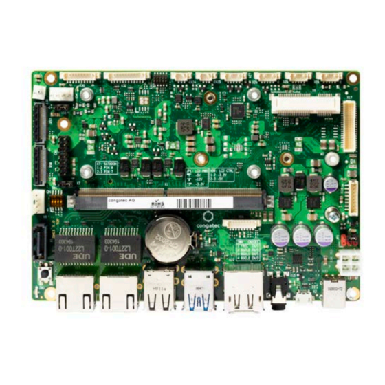
Page 11: Connector Layout
Use the mouse icon in the top left hand corner of the destination page to return to the connector layout picture. Copyright © 2020 congatec AG SMC1m10 11/50... - Page 12 Copyright © 2020 congatec AG SMC1m10 12/50...
-
Page 13: Specifications
Boot from external BIOS flash Note Available only on ARM-based variant (PN:020750) The module must also support the features for them to function. Refer to the module’s user’s guide for information about supported features. Copyright © 2020 congatec AG SMC1m10 13/50... -
Page 14: Mechanical Dimensions
Storage: 5% to 95% Note The above operating temperatures must be strictly adhered to at all times. The maximum operating temperature refers to any measurable spot on the modules surface. Humidity specifications are for non-condensing conditions. Copyright © 2020 congatec AG SMC1m10 14/50... -
Page 15: Connector Description
CSI0_CK+ CSI1_RX0- CSI0_CK- CSI1_RX1+ CSI0_RX0+ CSI1_RX1- CSI0_RX0- CSI1_RX2+ CSI0_RX1+ CSI1_RX2- CSI0_RX1- CSI1_RX3+ GBE1_MDI0+ CSI1_RX3- GBE1_MDI0- GBE1_LINK100# GBE0_MDI3- GBE1_MDI1+ GBE0_MDI3+ GBE1_MDI1- GBE0_LINK100# GBE1_LINK1000# GBE0_LINK1000# GBE1_MDI2+ GBE0_MDI2- GBE1_MDI2- GBE0_MDI2+ GBE0_LINK_ACT# GBE1_MDI3+ GBE0_MDI1- GBE1_MDI3- GBE0_MDI1+ GBE1_CTREF Copyright © 2020 congatec AG SMC1m10 15/50... - Page 16 SPI0_DIN MDIO_DAT SPI0_DO I2C_GP_CK SATA_TX+ I2C_GP_DAT SATA_TX- HDA_SYNC / I2S2_LRCK HDA_SDO / I2S2_SDOUT SATA_RX+ HDA_SDI / I2S2_SDIN SATA_RX- HDA_CK / I2S2_CK SATA_ACT# ESPI_CS0# USB5_EN_OC# ESPI_CS1# ESPI_IO_2 ESPI_CK ESPI_IO_3 ESPI_IO_1 ESPI_RESET# ESPI_IO_0 USB5+ USB5- Copyright © 2020 congatec AG SMC1m10 16/50...
- Page 17 USB1_EN_OC# USB3+ USB3- USB2+ USB2- USB2_SSTX+ USB2_EN_OC# USB2_SSTX- RSVD RSVD USB2_SSRX+ USB3_EN_OC# USB2_SSRX- PCIE_A_RST# PCIE_B_RST# USB4_EN_OC# PCIE_C_RST# PCIE_B_CKREQ# PCIE_C_RX+ PCIE_A_CKREQ# PCIE_C_RX- PCIE_C_REFCK+ PCIE_C_TX+ PCIE_C_REFCK- PCIE_C_TX- PCIE_A_REFCK+ PCIE_B_REFCK+ PCIE_A_REFCK- PCIE_B_REFCK- PCIE_A_RX+ PCIE_B_RX+ PCIE_A_RX- PCIE_B_RX- Copyright © 2020 congatec AG SMC1m10 17/50...
- Page 18 GPIO8 S117 LVDS1_2+ / eDP1_TX2+ / DSI1_D2+ P117 GPIO9 S118 LVDS1_2- / eDP1_TX2- / DSI1_D2- P118 GPIO10 S119 P119 GPIO11 S120 LVDS1_3+ / eDP1_TX3+ / DSI1_D3+ P120 S121 LVDS1_3- / eDP1_TX3- / DSI1_D3- Copyright © 2020 congatec AG SMC1m10 18/50...
- Page 19 PCIE_WAKE# P146 CAN1_RX S147 VDD_RTC P147 VDD_IN S148 LID# P148 VDD_IN S149 SLEEP# P149 VDD_IN S150 VIN_PWR_BAD# P150 VDD_IN S151 CHARGING# P151 VDD_IN S152 CHARGER_PRSNT# P152 VDD_IN S153 CARRIER_STBY# P153 VDD_IN S154 CARRIER_PWR_ON Copyright © 2020 congatec AG SMC1m10 19/50...
-
Page 20: Power Supply Connectors
The conga-SMC1 provides DC power jack X33. The power input has a 15 A fuse and reverse voltage protection. Table 6 X33 Pinout Description Function Inner Shell +12–24 V ± 5% Outer Shell Connector Type X33: DC power plug (7.4 x 5.1 mm) Copyright © 2020 congatec AG SMC1m10 20/50... -
Page 21: Mini-Fit 4-Pin Connector
ACPI State Description Green - Steady on S0 System on and running Red - Steady on Pseudo G3 Deep sleep with minimum power consumption Green - Blinking S3-S5 Standby or Suspend to RAM/Disk Copyright © 2020 congatec AG SMC1m10 21/50... -
Page 22: Vin_Pwr_Bad# Control
Danger of explosion if battery is incorrectly replaced. Replace only with the same or equivalent type recommended by the manufacturer. Dispose of used batteries according to the manufacturer’s instructions. Connector Type X44: 1.25 mm, 2-pin PicoBlade header (Molex 530470210) Possible Mating Connector: Molex 51021-0200 Copyright © 2020 congatec AG SMC1m10 22/50... -
Page 23: Extension Sockets
1 2 3 4 M.2 Key E (X12) PCIe Lane B USB 2.0 Signals M.2 Key B (X10) SIM Card Slot (X11) PCIe Lane C SW6.3 PCIe Lane D 1 2 3 4 USB 2.0 Signals Copyright © 2020 congatec AG SMC1m10 23/50... -
Page 24: Mini Card Socket
The conga-SMC1 provides a Mini Card socket X6. The socket supports full or half size PCIe or USB 2.0 cards or both. Note Use switch 3 of DIP SW6 to route the UIM signals from mini Card socket to M.2 type B socket. Connector Type X6: Mini PCIe card Copyright © 2020 congatec AG SMC1m10 24/50... -
Page 25: M.2 Key B Socket
X10: M.2 card size 2280/3042 4.2.3 M.2 Key E Socket The conga-SMC1 provides an M.2 key E, type 2230 socket (X12) for connecting a PCIe WLAN card. Connector Type X12: M.2 card size 2230 Copyright © 2020 congatec AG SMC1m10 25/50... -
Page 26: Sim Card Slot
Table 11 SW6.4 - SD Card Write Protection SW6.4 Switch Configuration Description SW6.4 Enable SD card write protection 1 2 3 4 Disable SD card write protection (default) Connector Type X23: Micro-SD card Copyright © 2020 congatec AG SMC1m10 26/50... -
Page 27: Display Connectors
The conga-SMC1 provides a DP++ port on connector X22 (upper port). You can connect a DP++ to HDMI dongle to the DP++ port if your module supports it. Connector Type X22: Standard DP cable Copyright © 2020 congatec AG SMC1m10 27/50... -
Page 28: Hdmi
VCC (fuse with 1 A hold current at 25ºC) VCC (fuse with 1.5 A hold current at 25ºC) VCC_EDID (+3.3 V) I2C_LCD_CK (EDID_CLK) I2C_LCD_DAT (EDID_DATA) LCD0_VDD_EN (enable for external VCC source; 3.3V or 5V level output control via X56) Copyright © 2020 congatec AG SMC1m10 28/50... -
Page 29: Panel Voltage Selection Jumper
The conga-SMC1 (connector X17) supports 3.3 V, 5 V and 12 V LCD panels. Use jumper JP1 to set the panel voltage. Table 13 JP1 Pinout Description Jumper Panel Voltage Pin 2 Pin 6 12 V No Pin No Pin 3.3 V (default) Connector Type Pin 3 JP1: 2.54 mm grid jumper Copyright © 2020 congatec AG SMC1m10 29/50... -
Page 30: Lcd Control Voltage Selection Jumper
The backlight enable and control signals are 3.3 V or 5 V output signals. Select the voltage level with jumper X56. Connector Type X19: 2 mm, 8-pin Crimp style connector (JST B8B-ZR-SM4-TF) Possible Mating Connector: JST ZHR-8 Copyright © 2020 congatec AG SMC1m10 30/50... -
Page 31: Mipi-Csi Connectors
The CSI0 interface—the first camera interface (X57) supports up to two differential data lanes Table 16 X57 Pinout Description Pin Signal Signal CSI0_RX0- I2C_CAM0_CK I2C_CAM0_DAT CSI0_CK+ CSI0_CK- CSI0_RX1+ +V5S CSI0_RX1- +V5S +V5S CSI0_RX0+ Connector Type X57: 0.5 mm pitch, 28-pin flat foil connector (Hirose FH41-28S-0.5SH(05)) Copyright © 2020 congatec AG SMC1m10 31/50... -
Page 32: Csi1 Interface
X58 Pinout Description Pin Signal Signal CSI1_RX0- CSI1_RX3+ CSI1_RX3- CSI1_RX2+ CSI1_RX2- I2C_CAM1_CK I2C_CAM1_DAT CSI1_CK+ CSI1_CK- CSI1_RX1+ +V5S CSI1_RX1- +V5S +V5S CSI1_RX0+ Connector Type X58: 0.5 mm pitch, 28-pin flat foil connector (Hirose FH41-28S-0.5SH(05)) Copyright © 2020 congatec AG SMC1m10 32/50... -
Page 33: Usb Connectors
X3 - Dual Stacked X6 - miniPCIe USB Type A SMARC 2.0 Connector USB2 (3.0) X4 - Dual Stacked USB3 (3.0) USB Type A USB4 (2.0) X10 - M.2 Type B USB5 (2.0) Not Used Copyright © 2020 congatec AG SMC1m10 33/50... -
Page 34: Micro Usb Type-Ab (Otg)
4.7.1 Micro USB Type-AB (OTG) The conga-SMC1 features a micro USB Type-AB port with OTG capability on connector X2. Note Available only on ARM-based variant. Connector Type X2: Micro USB Type AB receptacle Copyright © 2020 congatec AG SMC1m10 34/50... -
Page 35: Dual Stacked Usb 2.0 Type-A
X3: USB Type A receptacle 4.7.3 Dual Stacked USB 3.0 Type-A The conga-SMC1 provides two USB 3.0 ports via connector X4. Each port provides up to 1 A. Connector Type X4: USB Type A receptacle Copyright © 2020 congatec AG SMC1m10 35/50... -
Page 36: Sata Connectors
Table 19 X8 Pinout Description Pin Signal +5 V (1.5 A fuse) +12 V (1.5 A fuse) Connector Type X8: 2.5 mm pitch, 4-pin header (TE 171825-4) ) Possible Mating Connector: TE 171822-4 Copyright © 2020 congatec AG SMC1m10 36/50... -
Page 37: Gigabit Ethernet (Gbe)
The conga-SMC1 provides headphone-OUT or stereo Line-OUT and MIC-IN signals on connector X15. The pinout of the connector is compliant with the Cellular Telecommunications Industry Association (CTIA) standard by default. For Open Mobile Terminal Platform (OMTP) standard, you need a customized conga-SMC1 variant (BOM option). Note Jack detection is not supported. Copyright © 2020 congatec AG SMC1m10 37/50... -
Page 38: Audio Header
Digital MIC serial clock For I2S (PN: 020750): 1.8 V level For HDA (PN: 020751): 3.3 V level Connector Type X64: 9-pin, 1.25 mm pitch picoblade header (Molex 0533980971) Possible Mating Connector: Molex 0510210900 Copyright © 2020 congatec AG SMC1m10 38/50... -
Page 39: Com Port Headers
DIP SW3 - COM Port Configuration Switch Configuration Description SW3.1 COM 0 RS422/RS485 standard COM 0 RS232 standard (default) 1 2 3 4 SW3.2 COM 2 RS422/RS485 standard COM 2 RS232 standard (default) Copyright © 2020 congatec AG SMC1m10 39/50... -
Page 40: Com 1 And 3 (Rs232)
Table 25 X28/X29 Pinout Description X28/X29 Pin Signal Description Ground Transmit data Not connected Not connected Receive data Connector Type X28,X29: 5-pin, 1.25 mm pitch picoblade header (Molex 0533980571) Possible Mating Connector: Molex 0510210500 Copyright © 2020 congatec AG SMC1m10 40/50... -
Page 41: Gpio Header
2. Pins 2 and 3 are for GPIO12 and GPIO13 respectively because we used GPIO5 and GPIO6 for fan control by default. Connector Type X37: 10-pin, 1.25 mm pitch picoblade header (Molex 0532611071) Possible Mating Connector: Molex 0510211000 Copyright © 2020 congatec AG SMC1m10 41/50... -
Page 42: I²C Bus/Sm Bus Header
ESPI_IO3 ESPI master data input/output 3 Empty ESPI_IO2 ESPI master data input/output 2 Pin 1 ESPI_RESET# ESPI reset output ESPI_IO1 ESPI master data input/output 1 Master input, slave output in single I/O mode Copyright © 2020 congatec AG SMC1m10 42/50... -
Page 43: Spi Device Header
SPI0_CLK SPI clock input Pin 1 Ground SPI0_DOUT SPI flash output pin Not connected Not connected by default Note Use only 1.8 V SPI flash. Connector Type X36: 1.27 mm, 2x5 pin female Copyright © 2020 congatec AG SMC1m10 43/50... -
Page 44: Boot Selection Switch
Table 31 DIP SW4.1 Configuration Switch Configuration Description SW4.1 Normal operation (default) 1 2 3 4 Force recovery mode Table 32 Switch SW5 Configuration Switch Configuration Description Normal operation (default) Force recovery mode Copyright © 2020 congatec AG SMC1m10 44/50... -
Page 45: Test Mode/Wireless-Disable Mode
Additionally, connector X38 may be used for powering CAN devices or auxiliary fan. Table 34 X24/X25 Pinout Description X24/X25 X24 - CAN 0 X25 - CAN 1 Pin Signal Signal CAN0_H CAN1_H CAN0_L CAN1_L Copyright © 2020 congatec AG SMC1m10 45/50... -
Page 46: Cpu Fan Header
2. FAN_TACHOIN fan output shall provide two pulses per revolution. 3. The fan must pull up the FAN_CTRL signal to high logic level Connector Type X54: 2.54 mm, 4-pin grid female fan connector Copyright © 2020 congatec AG SMC1m10 46/50... -
Page 47: Front Panel Header
LED indicates activity on the SATA connector X5 (onboard series resistor makes it possible to connect the LEDs directly to the pins) SATA_ACT# (cathode) Connector Type X32: 12-pin, 1.25 mm pitch (Molex 53398-1271) Possible Mating Connector: Molex 0510211200 Copyright © 2020 congatec AG SMC1m10 47/50... -
Page 48: Feature Connector
Input signal that indicates the presence of a battery charger. Note: Connect to open-drain output 3.3 V Power source Connector Type X31: 10-pin, 1.25 mm pitch picoblade header (Molex 0532611071) Possible Mating Connector: Molex 0510211000 Copyright © 2020 congatec AG SMC1m10 48/50... -
Page 49: Additional Features
The conga-SMC1 offers an optional right-angle button (BOM option) Debug Feature—Internal Use Only The conga-SMC1 provides a JTAG interface via test points TP7-TP10. This interface is used for programming and debugging the congatec board controller (internal use only). Use switch 1 of DIP SW6 to enable test mode. -
Page 50: Mechanical Dimensions
Mechanical Dimensions 142.82 8.89 8.89 142.82 All dimensions are in millimeters. Copyright © 2020 congatec AG SMC1m10 50/50...
Need help?
Do you have a question about the SMARC conga-SMC1 and is the answer not in the manual?
Questions and answers