Table of Contents
Advertisement
Quick Links
Advertisement
Table of Contents

Related Manuals for Universal Robots UR3/CB3


Summary of Contents for Universal Robots UR3/CB3
- Page 1 User Manual UR3/CB3 Original instructions (en) US version...
- Page 3 User Manual UR3/CB3 Version 3.3.3 Original instructions (en) US Version Serial number UR3/CB3:...
- Page 4 The information contained herein is the property of Universal Robots A/S and shall not be reproduced in whole or in part without prior written approval of Universal Robots A/S. The information herein is subject to change without notice and should not be construed as a commitment by Universal Robots A/S.
-
Page 5: Table Of Contents
Mounting ......I-23 Maximum Payload ......I-28 Version 3.3.3 UR3/CB3... - Page 6 EMC Test Certificate ......I-62 C Applied Standards I-63 D Technical Specifications I-71 UR3/CB3 Version 3.3.3...
- Page 7 13.1.2 Feature and Tool Position ..... . II-38 13.1.3 Move Tool ......II-38 Version 3.3.3 UR3/CB3...
- Page 8 ..... . II-81 14.9 Command: Wait ......II-82 UR3/CB3 Version 3.3.3...
- Page 9 15.6 Set Time....... II-117 15.7 URCaps Setup ......II-118 Glossary II-119 Index II-121 Version 3.3.3 UR3/CB3...
- Page 10 UR3/CB3 viii Version 3.3.3...
-
Page 11: Preface
• Control box with teach pendant; • Mounting bracket for the control box; • Mounting bracket for the teach pendant; • Key for opening the control box; • Mains cable compatible with your region; • Tool cable; • Stylus pen with laser; Version 3.3.3 UR3/CB3... -
Page 12: Important Safety Notice
It is also helpful, though not necessary, to be famil- iar with elementary concepts of programming. No special knowledge about robots in general or Universal Robots in particular is required. Where to Find More Information The support website (http://www.universal-robots.com/support), available to all UR distributors, contains additional information, such as: •... -
Page 13: I Hardware Installation Manual
Part I Hardware Installation Manual... -
Page 15: Safety
• Validating that the total system is designed and installed correctly; • Specifying instructions for use; • Marking the robot installation with relevant signs and contact information of the integrator; • Collecting all documentation in a technical file; including the risk assessment and this manual. Version 3.3.3 UR3/CB3... -
Page 16: Limitation Of Liability
WARNING: This indicates a potentially hazardous situation which, if not avoided, could result in injury or major damage to the equipment. WARNING: This indicates a potentially hazardous hot surface which, if touched, could result in injury. UR3/CB3 Version 3.3.3... -
Page 17: General Warnings And Cautions
Other warnings and cautions are present throughout the manual. DANGER: Make sure to install the robot and all electrical equipment according to the specifications and warnings found in the Chapters 4 and 5. Version 3.3.3 UR3/CB3... - Page 18 10. Be aware of robot movement when using the teach pendant. 11. Do not enter the safety range of the robot or touch the robot when the system is in operation. UR3/CB3 Version 3.3.3...
- Page 19 13. Never modify the robot. A modification might create hazards that are unforeseen by the integrator. All authorized reassem- bling shall be done according to the newest version of all rele- vant service manuals. UNIVERSAL ROBOTS DISCLAIMS ANY LIABILITY IF THE PRODUCT IS CHANGED OR MODIFIED IN ANY WAY.
-
Page 20: Intended Use
It is recom- mended to test the robot program using temporary waypoints outside the workspace of other machines. Universal Robots can- not be held responsible for any damages caused to the robot or to other equipment due to programming errors or malfunction- ing of the robot. - Page 21 Applying the correct safety configuration settings is considered equivalent to bolting the robot into place and connecting safety-related equipment to safety-related I/Os. The integrator must prevent unauthorized persons from changing the safety configu- ration, e.g. by use of password protection. Version 3.3.3 UR3/CB3...
-
Page 22: Emergency Stop
(e.g. an enabling device to protect the integrator during set-up and programming). Universal Robots has identified the potential significant hazards listed below as haz- ards which must be considered by the integrator. Note that other significant hazards might be present in a specific robot installation. - Page 23 2. If the brake is released manually, gravitational pull can cause the robot arm to fall. Always support the robot arm, tool and work item when releasing the brake. Version 3.3.3 I-11 UR3/CB3...
-
Page 24: Movement Without Drive Power
1.9 Movement Without Drive Power UR3/CB3 I-12 Version 3.3.3... -
Page 25: Safety-Related Functions And Interfaces
The robot has a number of safety-related functions that can be used to limit the move- ment of its joints and of the robot Tool Center Point (TCP). The TCP is the center point of the output flange with the addition of the TCP offset. The limiting safety-related functions are: Version 3.3.3 I-13 UR3/CB3... -
Page 26: Stopping Times Of The Safety System
Violations of limits will hence only occur in exceptional cases. Nevertheless, if a limit is violated, the safety system issues a Stop Category 0. Stop Categories are according to IEC 60204-1, see Glossary for more details. UR3/CB3 I-14 Version 3.3.3... -
Page 27: Safety Modes
Normal and Reduced. Safety limits can be configured for each of these two modes. Reduced mode is active when the robot TCP is positioned beyond a Trigger Reduced mode plane or when triggered by a safety input. Version 3.3.3 I-15 UR3/CB3... - Page 28 The safety system issues a Stop Category 0 if a violation of these limits appears. WARNING: Notice that limits for the joint position, the TCP position, and the TCP orientation are disabled in Recovery Mode. Take caution when mov- ing the robot arm back within the limits. UR3/CB3 I-16 Version 3.3.3...
-
Page 29: Safety-Related Electrical Interfaces
Stop input, the robot arm is only allowed to start moving again after a positive edge on the safeguard reset input occurs. If any of the above properties are not satisfied, the safety system issues a Stop Category 0. Version 3.3.3 I-17 UR3/CB3... -
Page 30: Safety-Related Electrical Outputs
1000 ms 1250 ms System emergency stop 250 ms 1000 ms 1250 ms Safeguard stop 250 ms 1000 ms 1250 ms 2.5.2 Safety-related Electrical Outputs The table below gives an overview of the safety-related electrical outputs: UR3/CB3 I-18 Version 3.3.3... - Page 31 If a safety output is not set properly, the safety system issues a Stop Category 0, with the following worst-case reaction times: Safety Output Worst Case Reaction Time System emergency stop 1100 ms Robot moving 1100 ms Robot not stopping 1100 ms Reduced mode 1100 ms Not reduced mode 1100 ms Version 3.3.3 I-19 UR3/CB3...
- Page 32 2.5 Safety-related Electrical Interfaces UR3/CB3 I-20 Version 3.3.3...
-
Page 33: Transportation
Use proper lifting equipment. All regional and national guidelines for lifting shall be followed. Universal Robots cannot be held responsible for any damage caused by transportation of the equipment. 2. Make sure to mount the robot according to the mounting in- structions in chapter 4. - Page 34 UR3/CB3 I-22 Version 3.3.3...
-
Page 35: Mechanical Interface
Also, an accurate base counterpart can be purchased as an accessory. Figure 4.1 shows where to drill holes and mount the screws. The robot connector cable can be mounted through the side or through the bottom of the base. Version 3.3.3 I-23 UR3/CB3... -
Page 36: Mounting
Control Box The control box can be hung on a wall, or it can be placed on the ground. A clearance of 50 mm on each side is needed for sufficient airflow. Extra brackets for mounting can be bought. UR3/CB3 I-24 Version 3.3.3... - Page 37 4.3 Mounting Figure 4.1: Holes for mounting the robot. Use four M6 bolts. All measurements are in mm. Version 3.3.3 I-25 UR3/CB3...
- Page 38 4.3 Mounting Figure 4.2: The tool output flange, ISO 9409-1-50-4-M6. This is where the tool is mounted at the tip of the robot. All measures are in mm. UR3/CB3 I-26 Version 3.3.3...
- Page 39 A wet control box could cause death. 2. The control box and teach pendant must not be exposed to dusty or wet environments that exceed IP20 rating. Pay special atten- tion to environments with conductive dust. Version 3.3.3 I-27 UR3/CB3...
-
Page 40: Maximum Payload
figure 4.3. The center of gravity offset is defined as the distance between the center of the tool output flange and the center of gravity. Payload [kg] Center of gravity offset [mm] Figure 4.3: Relationship between the maximum allowed payload and the center of gravity offset. UR3/CB3 I-28 Version 3.3.3... -
Page 41: Electrical Interface
Keep the two channels separate so that a single fault cannot lead to loss of the safety function. 3. Some I/O inside the control box can be configured for either normal or safety-related I/O. Read and understand the com- plete section 5.3. Version 3.3.3 I-29 UR3/CB3... -
Page 42: Electrical Warnings And Cautions
EMC problems are found to happen usually in welding processes and are normally prompted by error mes- sages in the log. Universal Robots cannot be held responsible for any damages caused by EMC problems. 2. I/O cables going from the control box to other machinery and factory equipment may not be longer than 30m, unless extended tests are performed. -
Page 43: Controller I/O
• Safety I/O. • Configurable I/O. • General purpose I/O. It is very important that UR robots are installed according the electrical specifications, which are the same for all three different kinds of inputs. Version 3.3.3 I-31 UR3/CB3... - Page 44 [PWR - GND] Current [PWR - GND] External 24V input requirements Voltage [24V - 0V] Current [24V - 0V] The digital I/O are constructed in compliance with IEC 61131-2. The electrical specifi- cations are shown below. UR3/CB3 I-32 Version 3.3.3...
- Page 45 The two permanent safety inputs are the emergency stop and the safeguard stop. The emergency stop input is for emergency stop equipment only. The safeguard stop input is for all kinds of safety-related protective equipment. The functional difference is shown below. Version 3.3.3 I-33 UR3/CB3...
- Page 46 5.3.2.1 Default safety configuration The robot is shipped with a default configuration which enables operation without any additional safety equipment, see illustration below. Safety UR3/CB3 I-34 Version 3.3.3...
- Page 47 In this example the configured I/Os used are “CI0-CI1” and “CO0-CO1”. Configurable Outputs Configurable Outputs Configurable Inputs Configurable Inputs If more than two UR robots or other machines need to be connected, a safety PLC is needed to control the emergency stop signals. Version 3.3.3 I-35 UR3/CB3...
- Page 48 If the safeguard interface is used to interface a light curtain, a reset outside the safety perimeter is required. The reset button must be a two channel type. In this example the I/O configured for reset is “CI0-CI1”, see below. UR3/CB3 I-36 Version 3.3.3...
- Page 49 This example shows how to connect a load to be controlled from a digital output, see below. Digital Outputs LOAD 5.3.4 Digital input from a button The example below shows how to connect a simple button to a digital input. Version 3.3.3 I-37 UR3/CB3...
- Page 50 “Power”. • Use of equipment that works in current mode. Current signals are less sensitive to interferences. Input modes can be selected in the GUI, see part II. The electrical specifications are shown below. UR3/CB3 I-38 Version 3.3.3...
- Page 51 5.3.6.1 Using an analog output Below is an example of how to control a conveyor belt with an analog speed control input. Analog Power 5.3.6.2 Using an Analog Input Below is an example of how to connect an analog sensor. Version 3.3.3 I-39 UR3/CB3...
-
Page 52: Remote On/Off Control
Input current [ON / OFF] Activation time [ON] The following examples show how to use remote ON/OFF. NOTE: A special feature in the software can be used to load and start pro- grams automatically, see part II. UR3/CB3 I-40 Version 3.3.3... -
Page 53: Tool I/O
This connector provides power and control signals for grippers and sensors used on a specific robot tool. The following industrial cables are suitable: • Lumberg RKMV 8-354. The eight wires inside the cable have different colors. The different colors designate different functions, see table below: Version 3.3.3 I-41 UR3/CB3... -
Page 54: Tool Digital Outputs
The digital outputs are implemented as NPN. When a digital output is activated the corresponding connection is driven to GND, and when it is deactivated the corre- sponding connection is open (open-collector/open-drain). The electrical specifications are shown below: UR3/CB3 I-42 Version 3.3.3... -
Page 55: Tool Digital Inputs
Logical high voltage Input resistance An example of how to use a digital input is shown in the following subsection. 5.4.2.1 Using the Tool Digital Inputs The example below shows how to connect a simple button. POWER Version 3.3.3 I-43 UR3/CB3... -
Page 56: Tool Analog Inputs
5.4.3.2 Using the Tool Analog Inputs, Differential The example below shows how to connect an analog sensor with a differential output. Connect the negative output part to GND (0V) and it works in the same way as a non-differential sensor. POWER UR3/CB3 I-44 Version 3.3.3... -
Page 57: Ethernet
It is recommended to install a main switch to power off all equipment in the robot application as an easy means for lockout and tagout under service. The electrical specifications are shown in the table below. Version 3.3.3 I-45 UR3/CB3... -
Page 58: Robot Connection
The cable from the robot must be plugged into the connector at the bottom of the control box, see illustration below. Ensure that the connector is properly locked before turning on the robot arm. Disconnecting the robot cable may only be done when the robot power is turned off. UR3/CB3 I-46 Version 3.3.3... - Page 59 5.7 Robot connection CAUTION: 1. Do not disconnect the robot cable when the robot arm is turned 2. Do not extend or modify the original cable. Version 3.3.3 I-47 UR3/CB3...
- Page 60 5.7 Robot connection UR3/CB3 I-48 Version 3.3.3...
-
Page 61: Maintenance And Repair
Repairs shall only be performed by authorized system integrators or by Universal Robots. All parts returned to Universal Robots shall be returned according to the service man- ual. 6.1 Safety Instructions After maintenance and repair work, checks must be carried out to ensure the required safety level. -
Page 62: Safety Instructions
High voltages (up to 600 V) can be present inside these power supplies for several hours after the control box has been switched off. 5. Prevent water and dust from entering the robot arm or control box. UR3/CB3 I-50 Version 3.3.3... -
Page 63: Disposal And Environment
Fee for disposal and handling of electronic waste of UR robots sold on the Danish market is prepaid to DPA-system by Universal Robots A/S. Importers in countries covered by the European WEEE Directive 2012/19/EU must make their own regis- tration to the national WEEE register of their country. - Page 64 UR3/CB3 I-52 Version 3.3.3...
-
Page 65: Certifications
Note that a CE mark is not affixed according to this directive for partly completed ma- chinery. If the UR robot is used in a pesticide application, then note the presence of directive 2009/127/EC. The declaration of incorporation according to 2006/42/EC an- nex II 1.B. is shown in appendix B. Version 3.3.3 I-53 UR3/CB3... -
Page 66: Declarations According To Eu Directives
B. A CE mark is affixed according to CE marking directives above. Regarding waste of electric and electronic equipment see chapter 7. For information about standards applied during the development of the robot, see appendix C. UR3/CB3 I-54 Version 3.3.3... -
Page 67: Warranties
Warranty. Claims under the Warranty must be submitted within two months of the Warranty default becoming evident. Ownership of devices or components replaced by and returned to Universal Robots shall vest in Universal Robots. Any other claims resulting out of or in connection with the device shall be excluded from this Warranty. -
Page 68: Disclaimer
9.2 Disclaimer takes no responsibility for any errors or missing information. UR3/CB3 I-56 Version 3.3.3... -
Page 69: A Stopping Time And Stopping Distance
Stopping Distance (rad) Stopping time (ms) Joint 0 (BASE) 0.18 Joint 1 (SHOULDER) 0.20 Joint 2 (ELBOW) 0.15 According to IEC 60204-1, see Glossary for more details. Version 3.3.3 I-57 UR3/CB3... -
Page 70: Stop Category 0 Stopping Distances And Times
A.1 Stop Category 0 stopping distances and times UR3/CB3 I-58 Version 3.3.3... -
Page 71: B Declarations And Certificates
5260 Odense S Denmark hereby declares that the product described below Industrial robot UR3/CB3 Serial number may not be put into service before the machinery in which it will be incorporated is declared in confor- mity with the provisions of Directive 2006/42/EC, as amended by Directive 2009/127/EC, and with the regulations transposing it into national law. -
Page 72: Safety System Certificate
B.2 Safety System Certificate B.2 Safety System Certificate UR3/CB3 I-60 Version 3.3.3... -
Page 73: Environmental Test Certificate
B.3 Environmental Test Certificate B.3 Environmental Test Certificate Climatic and mechanical assessment sheet no. 1375 DELTA client DELTA project no. Universal Robots A/S T209612 and T209963 Energivej 25 5260 Odense S Denmark Product identification Robot system UR3, consisting of: UR3 Robot Arm CB 3.1 Control Box... -
Page 74: Emc Test Certificate
Telecom Agency in Denmark to carry out tasks referred to in Annex III of the European Council EMC Directive 2004/108/EC. The attestation of conformity is in accordance with Article 5 and refers to the essential requirements set out in Annex I. DELTA client Universal Robots A/S Energivej 25 5260 Odense S Denmark... -
Page 75: C Applied Standards
Safety of machinery – Safety-related parts of control systems Part 1: General principles for design Part 2: Validation The safety control system is designed as Performance Level d (PLd) according to the requirements of these standards. Version 3.3.3 I-63 UR3/CB3... - Page 76 3 structure. The safety-rated I/Os must be connected according to this manual to Category 3 safety-rated equipment to form a PLd structure of the complete safety function. According to ISO 13849-1, see Glossary for more details. UR3/CB3 I-64 Version 3.3.3...
- Page 77 The language is changed from British English to American English, but the content is the same. Note that part two (ISO 10218-2) of this standard is intended for the integrator of the robot system, and not Universal Robots. Version 3.3.3...
- Page 78 CSA added additional requirements for the user of the robot system. Some of these requirements might need to be addressed by the robot integrator. Note that part two (ISO 10218-2) of this standard is intended for the integrator of the robot system, and not Universal Robots. IEC 61000-6-2:2005 IEC 61000-6-4/A1:2010...
- Page 79 Manipulating industrial robots – Mechanical interfaces Part 1: Plates The tool flange on UR robots conforms to type 50-4-M6 of this standard. Robot tools should also be con- structed according to this standard to ensure proper fitting. Version 3.3.3 I-67 UR3/CB3...
- Page 80 UR robots are tested according to the test methods defined in these standards. IEC 61784-3:2010 EN 61784-3:2010 [SIL 2] Industrial communication networks – Profiles Part 3: Functional safety fieldbuses – General rules and profile definitions This standards defines requirements for safety-rated communication buses. UR3/CB3 I-68 Version 3.3.3...
- Page 81 The electrical circuitry of UR robots is designed in compliance with this standard. EUROMAP 67:2015, V1.11 Electrical Interface between Injection Molding Machine and Handling Device / Robot UR robots equipped with the E67 accessory module to interface injection molding machines comply with this standard. Version 3.3.3 I-69 UR3/CB3...
- Page 82 UR3/CB3 I-70 Version 3.3.3...
-
Page 83: D Technical Specifications
Power supply 100-240 VAC, 50-60 Hz Calculated operating life 35,000 hours Cabling Cable between robot and control box (6 m / 236 in) Cable between touchscreen and control box (4.5 m / 177 in) Version 3.3.3 I-71 UR3/CB3... - Page 84 UR3/CB3 I-72 Version 3.3.3...
-
Page 85: Polyscope Manual
Part II PolyScope Manual... -
Page 87: Safety Configuration
10 Safety Configuration 10.1 Introduction The robot is equipped with an advanced safety system. Depending on the particu- lar characteristics of the robot workspace, the settings for the safety system must be configured to guarantee the safety of all personnel and equipment around the robot. Applying settings defined by the risk assessment is the first thing the integrator must do. - Page 88 10.1 Introduction The safety settings consist of a number of limit values used to constrain the move- ments of the robot arm, and of safety function settings for the configurable inputs and outputs. They are defined in the following subtabs of the safety screen: •...
-
Page 89: Changing The Safety Configuration
10.2 Changing the Safety Configuration 10.2 Changing the Safety Configuration The safety configuration settings shall only be changed in compliance with the risk assessment conducted by the integrator. The recommended procedure for changing the safety configuration is as follows: 1. Make sure that the changes are in compliance with the risk assessment conducted by the integrator. -
Page 90: Tolerances
10.5 Safety Checksum 2. Revert back to the previously applied safety configuration. This will disregard all changes and allow you to continue to the desired destination. If no errors exist and attempting to navigate away, a different dialog appears with the following options: 1. -
Page 91: Safety Modes
10.6 Safety Modes 10.6 Safety Modes Under normal conditions (i.e. when no protective stop is in effect), the safety system operates in one of the following safety modes, each with an associated set of safety limits: Normal mode: The safety mode that is active by default; Reduced mode: Active when the robot TCP is positioned beyond a Trigger Reduced mode plane (see 10.12), or when triggered using a configurable input (see 10.13). -
Page 92: Password Lock
10.9 Apply 10.8 Password Lock All settings on this screen are locked until the correct safety password (see 15.3) is entered in the white text field at the bottom of the screen and the Unlock button is pressed. The screen can be locked again by clicking the Lock button. The Safety tab is automatically locked when navigating away from the safety configuration screen. -
Page 93: General Limits
10.10 General Limits Furthermore, on confirmation the changes are automatically saved as part of the cur- rent robot installation. See 13.5 for further information on saving the robot installation. 10.10 General Limits The general safety limits serve to limit the linear speed of the robot TCP as well as the force it may exert on the environment. - Page 94 10.10 General Limits Defining the general safety limits only defines the limits for the tool, and not the over- all limits of the robot arm. This means that although a speed limit is specified, it does not guarantee that other parts of the robot arm will obey this same limitation. When in Freedrive mode (see 13.1.5), and the current speed of the robot TCP is close to the Speed limit, the user will feel a repelling force which increases in magnitude the closer the speed comes to the limit.
- Page 95 10.10 General Limits Maximum. The force limit can be set to a value between 100 N (50 N for a UR3) and 250 N, and the power limit can be set to a value between 80 W and 1000 W. Note that the fields for limits in Reduced mode are disabled when neither a safety plane nor a configurable input is set to trigger it (see 10.12 and 10.13 for more details).
-
Page 96: Joint Limits
10.11 Joint Limits 10.11 Joint Limits Joint limits restrict the movement of individual joints in joint space, i.e. they do not refer to Cartesian space but rather to the internal (rotational) position of the joints and their rotational speed. The radio buttons in the upper portion of the subpanel make it possible to independently set up Maximum Speed and Position Range for the joints. -
Page 97: Boundaries
10.12 Boundaries The tolerance and unit for each limit are listed at the end of the row that corresponds to it. When a program is running, the speed of the robot arm is automatically adjusted in order to not exceed any of the entered values minus the tolerance (see 10.4). Note that the minus sign displayed with each tolerance value is only there to indicate that the tolerance is subtracted from the actual entered value. -
Page 98: Selecting A Boundary To Configure
10.12 Boundaries The configuration of each boundary limit is based on one of the features defined in the current robot installation (see 13.12). NOTE: It is highly recommended, that you create all features needed for the configuration of all the desired boundary limits and assign them ap- propriate names before editing the safety configuration. -
Page 99: Safety Plane Configuration
10.12 Boundaries boundary entries where the visibility toggle is selected (i.e. showing icon) in the Safety Boundaries section are displayed together with the current selected boundary limit. The (active) safety planes are shown in yellow and black with a small arrow represent- ing the plane normal, which indicates the side of the plane on which the robot TCP is allowed to be positioned. - Page 100 10.12 Boundaries Name The Name text field allows the user to assign a name to the selected safety plane. Change the name by tapping the text field and entering a new name. Copy Feature The position and normal of the safety plane is specified using a fea- ture (see 13.12) from the current robot installation.
- Page 101 10.12 Boundaries The selected safety mode is indicated by an icon in the corresponding entry in the Safety Boundaries panel. If the safety mode is set to Disabled, no icon is shown. Displacement When a feature has been selected in the drop down box in the lower left portion of the Safety Plane Properties panel, the safety plane can be trans- lated by tapping the Displacement text field in the lower right portion of this panel and entering a value.
-
Page 102: Tool Boundary Configuration
10.12 Boundaries When a transition from Reduced to Normal mode is caused by passing through a Trigger Reduced mode plane, a transition from the Reduced mode limit set to the Normal mode limit set occurs. As soon as the robot TCP passes through the Trigger Reduced mode plane, the more permissive of the Normal and Reduced mode limits is applied for each limit value. - Page 103 10.12 Boundaries The accepted value range together with the tolerance and unit of the deviation are listed next to the text field. Copy Feature The desired orientation of the robot tool is specified using a feature (see 13.12) from the current robot installation. The z-axis of the selected feature will be used as the desired tool orientation vector for this limit.
-
Page 104: Safety I/O
10.13 Safety I/O 10.13 Safety I/O This screen defines the Safety functions for configurable inputs and outputs (I/Os). The I/Os are divided between the inputs and outputs, and are paired up so that each function is providing a Category 3 and PLd I/O. Each Safety function can only control one pair of I/Os. - Page 105 10.13 Safety I/O for more details). When this input safety function is selected, a low signal given to the inputs causes the safety system to transition to Reduced mode. If necessary, the robot arm then decelerates to satisfy the Reduced mode limit set. Should the robot arm still violate any of the Reduced mode limits, it performs a Stop Category 0.
-
Page 106: Output Signals
10.13 Safety I/O 2. To select the operational mode from Polyscope, only the 3-Position Switch input must be configured and applied to the Safety Configuration. In this case, the default mode is Running. In order to switch to Programming mode, choose the “Program Robot”... -
Page 107: Begin Programming
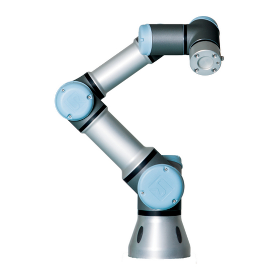
11 Begin programming 11.1 Introduction The Universal Robot arm is composed of tubes and joints. The joints with their usual names are shown in Figure 11.1. The Base is where the robot is mounted, and at the other end (Wrist 3) the tool of the robot is attached. By coordinating the motion of each of the joints, the robot can move its tool around freely, with the exception of the area directly above and directly below the base. -
Page 108: Turning The Control Box On And Off
11.2 Getting Started Figure 11.1: Joints of the robot. A: Base, B: Shoulder, C: Elbow and D, E, F: Wrist 1, 2, 3 5. Plug in the mains plug of the control box. WARNING: Tipping hazard. If the robot is not securely placed on a sturdy sur- face, the robot can fall over and cause an injury. -
Page 109: Quick Start
11.2 Getting Started (see 11.5) by touching the ON button on that screen, and then pressing Start. When a robot is started, it makes a sound and moves a little while releasing the brakes. The power to the robot arm can be turned off by touching the OFF button on the ini- tialization screen. - Page 110 11.2 Getting Started robot arm to a certain position, use either the Move tab (see 13.1), or simply pull the robot arm into place while holding the Freedrive button at the back side of the teach pendant. Besides moving through waypoints, the program can send I/O signals to other ma- chines at certain points in the robot’s path, and perform commands like if...then and loop, based on variables and I/O signals.
-
Page 111: Polyscope Programming Interface
11.3 PolyScope Programming Interface WARNING: 1. Do not drive the robot into itself or anything else as this may cause damage to the robot. 2. Keep your head and torso outside the reach (workspace) of the robot. Do not place fingers where they can be caught. 3. -
Page 112: Welcome Screen
11.4 Welcome Screen In this example, the Program tab is selected at the top level, and under that the Structure tab is selected. The Program tab holds information related to the cur- rently loaded program. If the Move tab is selected, the screen changes to the Move screen, from where the robot arm can be moved. -
Page 113: Initialization Screen
11.5 Initialization Screen • Run Program: Choose and run an existing program. This is the simplest way to operate the robot arm and control box. • Program Robot: Change a program, or create a new program. • Setup Robot: Change the language, set passwords, upgrade software, etc. •... - Page 114 11.5 Initialization Screen Active payload and installation When the robot arm is powered on, the payload mass used by the controller when operating the robot arm is shown in the small white text field. This value can be modified by tapping the text field and entering a new value. Note that setting this value does not modify the payload in the robot’s installation (see 13.6), it only sets the payload mass to be used by the controller.
- Page 115 11.5 Initialization Screen If the mounting verification passes, tapping the button releases all joint brakes and the robot arm becomes ready for normal operation. Note that the robot makes a sound and moves a little while releasing the brakes. • If the robot arm violates one of the safety limits after it starts up, it operates in a special Recovery mode.
- Page 116 11.5 Initialization Screen II-32 Version 3.3.3...
-
Page 117: On-Screen Editors
12 On-screen Editors 12.1 On-screen Expression Editor While the expression itself is edited as text, the expression editor has a number of buttons and functions for inserting the special expression symbols, such as for mul- tiplication and for less than or equal to. The keyboard symbol button in the top left of the screen switches to text-editing of the expression. -
Page 118: Pose Editor Screen
12.2 Pose Editor Screen 12.2 Pose Editor Screen On this screen you can specify target joint positions, or a target pose (position and orientation) of the robot tool. This screen is “offline” and does not control the robot arm directly. Robot The current position of the robot arm and the specified new target position are shown in 3D graphics. - Page 119 12.2 Pose Editor Screen When the target robot TCP no longer is in the proximity of the limit, the 3D represen- tation disappears. If the target TCP is in violation or very close to violating a boundary limit, the visualization of the limit turns red. Feature and tool position In the top right corner of the screen, the feature selector can be found.
- Page 120 12.2 Pose Editor Screen specified value was a tool coordinate, the robot arm will move to the target position using the MoveL movement type, while the robot arm will move to the target position using the MoveJ movement type, if a joint position was specified last. The different movement types are described in 14.5.
-
Page 121: Robot Control
13 Robot Control 13.1 Move Tab On this screen you can always move (jog) the robot arm directly, either by translat- ing/rotating the robot tool, or by moving robot joints individually. 13.1.1 Robot The current position of the robot arm is shown in 3D graphics. Push the magnifying glass icons to zoom in/out or drag a finger across to change the view. -
Page 122: Feature And Tool Position
13.1 Move Tab The tool orientation boundary limit is visualized with a spherical cone together with a vector indicating the current orientation of the robot tool. The inside of the cone represents the allowed area for the tool orientation (vector). When the robot TCP no longer is in the proximity of the limit, the 3D representation disappears. -
Page 123: I/O Tab
13.2 I/O Tab WARNING: 1. Make sure to use the correct installation settings (e.g. Robot mounting angle, weight in TCP, TCP offset). Save and load the installation files along with the program. 2. Make sure that the TCP settings and the robot mounting set- tings are set correctly before operating the Freedrive button. -
Page 124: Modbus Client I/O
13.3 MODBUS client I/O Configurable I/O’s can be reserved for special safety settings defined in the safety I/O configuration section of the installaton (see 10.13); those which are reserved will have the name of the safety function in place of the default or user defined name. Configurable outputs that are reserved for safety settings are not togglable and will be displaed as LED’s only. -
Page 125: Automove Tab
13.4 AutoMove Tab 13.4 AutoMove Tab The AutoMove tab is used when the robot arm has to move to a specific position in its workspace. Examples are when the robot arm has to move to the start position of a program before running it, or when moving to a waypoint while modifying a program. -
Page 126: Installation Load/Save
13.5 Installation Load/Save Auto Hold down the Auto button to move the robot arm as shown in the animation. Note: Release the button to stop the motion at any time! Manual Pushing the Manual button will take you to the MoveTab where the robot arm can be moved manually. -
Page 127: Installation Tcp Configuration
13.6 Installation TCP Configuration Load/Save text on the left side of the Installation tab. Saving an installation can be done by pressing the Save or Save As... button. Al- ternatively, saving a program also saves the active installation. To load a different in- stallation file, use the Load button. -
Page 128: Adding, Modifying And Removing Tcps
13.6 Installation TCP Configuration 13.6.1 Adding, modifying and removing TCPs To define a new TCP, hit the New button. The created TCP then automatically receives a unique name and becomes selected in the drop-down menu. The translation and rotation of the selected TCP can be modified by tapping the re- spective white text fields and entering new values. -
Page 129: Teaching Tcp Orientation
13.6 Installation TCP Configuration 1. Tap the Position button. 2. Choose a fixed point in the workspace of the robot. 3. Use the buttons on the right side of the screen to move the TCP to the chosen point from at least three different angles and to save the corresponding positions of the tool output flange. -
Page 130: Payload
13.6 Installation TCP Configuration 3. Use the button below to move to a position in which the orientation of the tool corresponding to the TCP coincides with the coordinate system of the selected feature. 4. Verify the calculated TCP orientation and set it onto the selected TCP using the Set button. -
Page 131: Installation Mounting
13.7 Installation Mounting 13.7 Installation Mounting Here the mounting of the robot arm can be specified. This serves two purposes: 1. Making the robot arm look right on the screen. 2. Telling the controller about the direction of gravity. The controller uses an advanced dynamics model to give the robot arm smooth and precise motions, and to make the robot arm hold itself when in Freedrive mode. -
Page 132: Installation I/O Setup
13.8 Installation I/O Setup lower part of the screen are used to rotate the mounting of the robot arm to match the actual mounting. WARNING: Make sure to use the correct installation settings. Save and load the installation files along with the program. 13.8 Installation I/O Setup Input and output signals can be given names. -
Page 133: Installation Safety
13.9 Installation Safety whenever no program is running. The eight digital standard outputs and the two tool outputs may furthermore be con- figured to reflect whether a program is currently running, so that the output is high when a program is running and otherwise low. Finally, it is also possible to specify whether an output can be controlled on the I/O tab (by either programmers, or both operators and programmers) or if it is only robot programs that may alter the output value. -
Page 134: Installation Modbus Client I/O Setup
13.11 Installation MODBUS client I/O Setup Pressing Create New will bring up a panel with a suggested name for the new vari- able. The name may be changed and its value may be entered by touching either text field. The OK-button can only clicked if the new name is unused in this installation. It is possible to change the value of an installation variable by highlighting the variable in the list and then clicking on Edit Value. - Page 135 13.11 Installation MODBUS client I/O Setup Here, the MODBUS client (master) signals can be set up. Connections to MODBUS servers (or slaves) on specified IP addresses can be created with input/output signals (registers or digital). Each signal has a unique name so it can be used in programs. Refresh Push this button to refresh all MODBUS connections.
- Page 136 13.11 Installation MODBUS client I/O Setup Set signal address This field shows the address on the remote MODBUS server. Use the on-screen key- pad to choose a different address. Valid addresses depends on the manufacturer and configuration of the remote MODBUS unit. Set signal name Using the on-screen keyboard, the user can give the signal a name.
-
Page 137: Installation Features
13.12 Installation Features Advanced Options • Update Frequency: This menu can be used to change the update frequency of the signal. This means the frequency with which requests are sent to the remote MODBUS unit for either reading or writing the signal value. •... - Page 138 13.12 Installation Features ammount of time to do this, even for a person skilled in the art of robot programming and installation. Often this task involves the calculation of 4x4 matrices. Particularly, the representation of orientation is complicated for a person that lacks the required experience to understand this problem.
- Page 139 13.12 Installation Features Set or Change Position Use this button to set or change the selected feature. The Move screen will appear and a new position of the feature can be set. Move Robot to Feature Pressing this button will move the robot arm towards the selected feature. At the end of this movement, the coordinate systems of the feature and the TCP will coincide, except for a 180 degree rotation about the x-axis.
- Page 140 13.12 Installation Features line. The position of the line coordinate system is the same as the position for the first sub point. Add Plane Push this button to add a plane feature to the installation. A plane is defined by three sub point features.
-
Page 141: Conveyor Tracking Setup
13.13 Conveyor Tracking Setup 13.13 Conveyor Tracking Setup When using a conveyor, the robot can be configured to track it’s movement. The Con- veyor Tracking Setup provides options for configuring the robot to work with absolute and incremental encoders, as well as, linear and circular conveyors. Conveyor Parameters Incremental encoders can be connected to digital inputs 0 to 3. - Page 142 13.14 Installation Default Program The field Ticks per meter is used as the number of ticks the encoder generates when the conveyor moves one meter. ticks per revolution of encoder Ticks per meter (13.1) radius of encoder disc[m] Circular conveyors When tracking a circular conveyor, the center point of the conveyor (circle) must be defined.
-
Page 143: Installation Default Program
13.14 Installation Default Program 13.14.1 Loading a Default Program A default program can be chosen to be loaded when the control box is powered up. Furthermore, the default program will also be auto loaded when the Run Program screen (see 11.4) is entered and no program is loaded. 13.14.2 Starting a Default Program The default program can be auto started in the Run Program screen. -
Page 144: Log Tab
13.16 Load Screen 13.15 Log Tab Robot Health The top half of the screen displays the health of the robot arm and control box. The left part shows information related to the control box of the robot, while the right part shows information about each robot joint. Each robot joint shows information for temperaure of the motor and electronics, the load of the joint and the voltage at the joint. - Page 145 13.16 Load Screen NOTE: Running a program from a USB drive is not recommended. To run a program stored on a USB drive, first load it and then save it in the local programs folder using the Save As... option in the File menu.
- Page 146 13.16 Load Screen By selecting a folder name in the list, the load dialog changes to that directory and displays it in the file selection area 13.16. File selection area In this area of the dialog the contents of the actual area is present. It gives the user the option to select a file by single clicking on its name or to open the file by double clicking on its name.
-
Page 147: Run Tab
13.17 Run Tab 13.17 Run Tab This tab provides a very simple way of operating the robot arm and control box, with as few buttons and options as possible. This can be usefully combined with password protecting the programming part of PolyScope (see 15.3), to make the robot into a tool that can run exclusively pre-written programs. - Page 148 13.17 Run Tab II-64 Version 3.3.3...
-
Page 149: Programming
14 Programming 14.1 New Program A new robot program can start from either a template or from an existing (saved) robot program. A template can provide the overall program structure, so only the details of the program need to be filled in. Version 3.3.3 II-65... -
Page 150: Program Tab
14.2 Program Tab 14.2 Program Tab The program tab shows the current program being edited. 14.2.1 Program Tree The program tree on the left side of the screen displays the program as a list of com- mands, while the area on the right side of the screen displays information relating to the current command. -
Page 151: Program Execution Indication
14.2 Program Tab 14.2.2 Program Execution Indication The program tree contains visual cues informing about the command currently being executed by the robot controller. A small indicator icon is displayed to the left of the command icon, and the name of the executing command and any commands of which this command is a sub-command (typically identified by the command icons) are highlighted with blue. -
Page 152: Undo/Redo Buttons
14.2 Program Tab lighted in yellow. Press the icon to exit search mode. 14.2.4 Undo/Redo Buttons The buttons with icons below the program tree serve to undo and redo changes made in the program tree and in the commands it contains. 14.2.5 Program Dashboard The lowest part of the screen is the Dashboard. -
Page 153: Variables
14.3 Variables Next to each program command is a small icon, which is either red, yellow or green. A red icon means that there is an error in that command, yellow means that the com- mand is not finished, and green means that all is OK. A program can only be run when all commands are green. -
Page 154: Command: Empty
14.4 Command: Empty 14.4 Command: Empty Program commands need to be inserted here. Press the Structure button to go to the structure tab, where the various selectable program lines can be found. A program cannot run before all lines are specified and defined. II-70 Version 3.3.3... -
Page 155: Command: Move
14.5 Command: Move 14.5 Command: Move The Move command controls the robot motion through the underlying waypoints. Waypoints have to be under a Move command. The Move command defines the ac- celeration and the speed at which the robot arm will move between those waypoints. Movement Types It is possible to select one of three types of movements: MoveJ, MoveL and MoveP each explained below. - Page 156 14.5 Command: Move tool positions of the waypoints are represented in. Of specific interest concerning feature spaces are variable features and variable waypoints. Variable features can be used when the tool position of a waypoint need to be determined by the actual value of the variable feature when the robot program runs.
- Page 157 14.5 Command: Move Cruise Deceleration Acceleration Time Figure 14.1: Speed profile for a motion. The curve is divided into three segments: acceleration, cruise and deceleration. The level of the cruise phase is given by the speed setting of the motion, while the steepness of the acceleration and deceleration phases is given by the acceleration parameter.
-
Page 158: Command: Fixed Waypoint
14.6 Command: Fixed Waypoint 14.6 Command: Fixed Waypoint A point on the robot path. Waypoints are the most central part of a robot program, telling the robot arm where to be. A fixed position waypoint is given by physically moving the robot arm to the position. Setting the waypoint Press this button to enter the Move screen where you can specify the robot arm’s po- sition for this waypoint. - Page 159 14.6 Command: Fixed Waypoint Blending Blending enables the robot to smoothly transition between two trajectories, without stopping at the waypoint between them. Example Consider a pick and place application as an example (see figure 14.2), where the robot is currently at Waypoint 1 (WP 1), and it needs to pick up an object at Waypoint 3 (WP 3).
- Page 160 14.6 Command: Fixed Waypoint • the trajectory types to blend from and to (MoveL, MoveJ) WP_1 WP_2 WP_3 Figure 14.3: Blend over WP 2 with radius r, initial blend position at p1 and final blend position at p2. O is an obstacle.
- Page 161 14.6 Command: Fixed Waypoint Conditional blend trajectories The blend trajectory is affected both by the way- point where the blend radius is set and the following one in the program tree. That is, in the program in figure 14.5 the blend around WP 1 is affected by WP 2. The con- sequence of this becomes more apparent when blending around WP 2 in this example.
- Page 162 14.6 Command: Fixed Waypoint waypoints. WP_2 WP_2 WP_1 WP_1 WP_3 WP_3 Figure 14.6: Joint space (MoveJ) vs. cartesian space (MoveL) movement and blend. Of the different combinations, bullets 2, 3 and 4 will result in trajectories that keep within the boundaries of the original trajectory in Cartesian space. An example of a blend between different trajectory types (bullet 2) can be seen in figure 14.7.
- Page 163 14.6 Command: Fixed Waypoint v1 << v2 v1 >> v2 WP_2 WP_2 WP_1 WP_1 WP_3 WP_3 Figure 14.8: Joint space blending when initial velocity v1 is significantly smaller than final velocity v2 or the opposite. Version 3.3.3 II-79...
-
Page 164: Command: Relative Waypoint
14.7 Command: Relative Waypoint 14.7 Command: Relative Waypoint A waypoint with the position given relative to the robot arm’s previous position, such as “two centimeters to the left”. The relative position is defined as the difference be- tween the two given positions (left to right). Note that repeated relative positions can move the robot arm out of its workspace. -
Page 165: Command: Variable Waypoint
14.8 Command: Variable Waypoint 14.8 Command: Variable Waypoint A waypoint with the position given by a variable, in this case calculated pos. The variable has to be a pose such as var=p[0.5,0.0,0.0,3.14,0.0,0.0]. The first three are x,y,z and the last three are the orientation given as a rotation vector given by the vector rx,ry,rz. -
Page 166: Command: Wait
14.9 Command: Wait 14.9 Command: Wait Waits for a given amount of time or for an I/O signal. II-82 Version 3.3.3... -
Page 167: Command: Set
14.10 Command: Set 14.10 Command: Set Sets either digital or analog outputs to a given value. The command can also be used to set the payload of the robot arm. Adjusting the payload weight can be necessary to prevent the robot from triggering a protective stop, when the weight at the tool differs from the expected payload. -
Page 168: Command: Popup
14.11 Command: Popup 14.11 Command: Popup The popup is a message that appears on the screen when the program reaches this command. The style of the message can be selected, and the text itself can be given using the on-screen keyboard. The robot waits for the user/operator to press the “OK” button under the popup before continuing the program. -
Page 169: Command: Halt
14.12 Command: Halt 14.12 Command: Halt The program execution stops at this point. Version 3.3.3 II-85... -
Page 170: Command: Comment
14.13 Command: Comment 14.13 Command: Comment Gives the programmer an option to add a line of text to the program. This line of text does not do anything during program execution. II-86 Version 3.3.3... -
Page 171: Command: Folder
14.14 Command: Folder 14.14 Command: Folder A folder is used to organize and label specific parts of a program, to clean up the program tree, and to make the program easier to read and navigate. A folder does not in itself do anything. Version 3.3.3 II-87... -
Page 172: Command: Loop
14.15 Command: Loop 14.15 Command: Loop Loops the underlying program commands. Depending on the selection, the underly- ing program commands are either looped infinitely, a certain number of times or as long as the given condition is true. When looping a certain number of times, a dedi- cated loop variable (called loop 1 in the screen shot above) is created, which can be used in expressions within the loop. -
Page 173: Command: Subprogram
14.16 Command: SubProgram 14.16 Command: SubProgram A Sub Program can hold program parts that are needed several places. A Sub Program can be a seperate file on the disk, and can also be hidden to protect against accidental changes to the SubProgram. Version 3.3.3 II-89... - Page 174 14.16 Command: SubProgram Command: Call SubProgram A call to a sub program will run the program lines in the sub program, and then return to the following line. II-90 Version 3.3.3...
-
Page 175: Command: Assignment
14.17 Command: Assignment 14.17 Command: Assignment Assigns values to variables. An assignment puts the computed value of the right hand side into the variable on the left hand side. This can be useful in complex programs. Version 3.3.3 II-91... -
Page 176: Command: If
14.18 Command: If 14.18 Command: If An “if...else” construction can make the robot change its behavior based on sensor inputs or variable values. Use the expression editor to describe the condition under which the robot should proceed to the sub-commands of this If. If the condition is evaluated to True, the lines inside this If are executed. -
Page 177: Command: Script
14.19 Command: Script 14.19 Command: Script This command gives access to the underlying real time script language that is executed by the robot controller. It is intended for advanced users only and instructions on how to use it can be found in the Script Manual on the support website (http://www. universal-robots.com/support). -
Page 178: Command: Event
14.20 Command: Event 14.20 Command: Event An event can be used to monitor an input signal, and perform some action or set a variable when that input signal goes high. For example, in the event that an output signal goes high, the event program can wait for 200ms and then set it back to low again. -
Page 179: Command: Thread
14.21 Command: Thread 14.21 Command: Thread A thread is a parallel process to the robot program. A thread can be used to control an external machine independently of the robot arm. A thread can communicate with the robot program with variables and output signals. Version 3.3.3 II-95... -
Page 180: Command: Switch
14.22 Command: Switch 14.22 Command: Switch A “Switch Case” construction can make the robot change behavior based on sensor inputs or variable values. Use the expression editor to describe the base condition and define the cases under which the robot should proceed to the sub-commands of this Switch. -
Page 181: Command: Pattern
14.23 Command: Pattern 14.23 Command: Pattern The Pattern command can be used to cycle through positions in the robot program. The pattern command corresponds to one position at each execution. A pattern can be given as one of four types. The first three, “Line”, “Square” or “Box” can be used for positions in a regular pattern. -
Page 182: Command: Force
14.24 Command: Force A “Box” pattern uses three vectors to define the side of the box. These three vectors are given as four points, where the first vector goes from point one to point two, the second vector goes from point two to point three, and the third vector goes from point three to point four. - Page 183 14.24 Command: Force a workpiece. Force mode also supports applying certain torques around predefined axes. Note that if no obstacles are met in an axis where a non-zero force is set, the robot arm will try to accelerate along/about that axis. Although an axis has been selected to be compliant, the robot program will still try to move the robot along/around that axis.
- Page 184 14.24 Command: Force robot TCP and the origin of the selected feature is required to be at least 10 mm. Note that the task frame will change at runtime as the position of the robot TCP changes. The x- and z-axis of the task frame are dependent on the original orien- tation of the selected feature.
-
Page 185: Command: Pallet
14.25 Command: Pallet When the Test button is on and the Freedrive button on the back of the Teach Pen- dant is pressed, the robot will perform as if the program had reached this force com- mand, and this way the settings can be verified before actually running the complete program. -
Page 186: Command: Seek
14.26 Command: Seek 3. Use the selector on the sequence command screen to define which of the way- points in the sequence should correspond to the pattern positions. Pallet Sequence/Anchorable Sequence In an Pallet Sequence node, the motions of the robot arm are relative to the pallet position. - Page 187 14.26 Command: Seek Stacking When stacking, the robot arm moves to the starting position, and then moves opposite the direction to search for the next stack position. When found, the robot remembers the position and performs the special sequence. The next time round, the robot starts the search from the remembered position incremented by the item thickness along the direction.
- Page 188 14.26 Command: Seek Destacking When destacking, the robot arm moves from the starting position in the given direc- tion to search for the next item. The condition on the screen determines when the next item is reached. When the condition becomes satisfied, the robot remembers the po- sition and performs the special sequence.
- Page 189 14.26 Command: Seek Direction The direction is given by two positions, and is calculated as the position difference from the first positions TCP to the second positions TCP. Note: A direction does not consider the orientations of the points. Next Stacking Position Expression The robot arm moves along the direction vector while continuously evaluating whether the next stack position has been reached.
-
Page 190: Command: Conveyor Tracking
14.29 Graphics Tab 14.27 Command: Conveyor Tracking When using a conveyor, the robot can be configured to track it’s movement. A pro- gram node is available for tracking a conveyor, Conveyor Tracking. When the Conveyor Tracking defined in the installation is configured correctly, a linear or cir- cular conveyor can be tracked. - Page 191 14.29 Graphics Tab the current position of the robot arm, and the “shadow” of the robot arm shows how the robot arm intends to reach the waypoint selected in the left hand side of the screen. If the current position of the robot TCP comes close to a safety or trigger plane, or the orientation of robot tool is near the tool orientation boundary limit (see 10.12), a 3D representation of the proximate boundary limit is shown.
-
Page 192: Structure Tab
14.30 Structure Tab 14.30 Structure Tab The program structure tab gives an opportunity for inserting, moving, copying and removing the various types of commands. To insert new commands, perform the following steps: 1) Select an existing program command. 2) Select whether the new command should be inserted above or below the selected command. -
Page 193: Variables Tab
14.31 Variables Tab 14.31 Variables Tab The Variables tab shows the live values of variables in the running program, and keeps a list of variables and values between program runs. It only appears when it has information to display. The variables are ordered alphabetically by their names. The variable names on this screen are shown with at most 50 characters, and the values of the variables are shown with at most 500 characters. -
Page 194: Command: Variables Initialization
14.32 Command: Variables Initialization 14.32 Command: Variables Initialization This screen allows setting variable values before the program (and any threads) start executing. Select a variable from the list of variables by clicking on it, or by using the variable selector box. For a selected variable, an expression can be entered that will be used to set the variable value at program start. -
Page 195: Setup Screen
15 Setup Screen • Initialize Robot Goes to the initialization screen, see 11.5. • Language and Units Configure the language and units of measurements for the user interface, see 15.1. • Update Robot Upgrades the robot software to a newer version, see 15.2. •... -
Page 196: Language And Units
15.1 Language and Units 15.1 Language and Units Language and units used in PolyScope can be selected on this screen. The selected language will be used for the text visible on the various screens of PolyScope as well as in the embedded help. Tick off “English programming” to have the names of com- mands within robot programs written in English. -
Page 197: Update Robot
15.2 Update Robot 15.2 Update Robot Software updates can be installed from USB flash memory. Insert an USB memory stick and click Search to list its contents. To perform an update, select a file, click Update, and follow the on-screen instructions. WARNING: Always check your programs after a software upgrade. -
Page 198: Set Password
15.3 Set Password 15.3 Set Password Two passwords are supported. The first is an optional System password which pre- vents unauthorized modification of the setup of the robot. When the System password is set, programs can be loaded and executed without the password, but the user must enter the correct password in order to create or change programs. -
Page 199: Calibrate Screen
15.4 Calibrate Screen 15.4 Calibrate Screen Calibrating the touch screen. Follow the on-screen instructions to calibrate the touch screen. Preferably use a pointed non-metallic object, such as a closed pen. Patience and care help achieve a better result. Version 3.3.3 II-115... -
Page 200: Setup Network
15.5 Setup Network 15.5 Setup Network Panel for setting up the Ethernet network. An Ethernet connection is not necessary for the basic robot functions, and is disabled by default. II-116 Version 3.3.3... -
Page 201: Set Time
15.6 Set Time 15.6 Set Time Set the time and date for the system and configure the display formats for the clock. The clock is displayed at the top of the Run Program and Program Robot screens. Tap- ping on it will show the date briefly. The GUI needs to be restarted for changes to take effect. -
Page 202: Urcaps Setup
15.7 URCaps Setup 15.7 URCaps Setup In the top list an overview of all installed URCaps is presented. Clicking on a URCap displays its meta information (including the name of the URCap, the version, license etc.) in the URCap Information area below the list. Click the + button in the bottom of the screen to install a new URCap. -
Page 203: Glossary
Glossary Stop Category 0: Robot motion is stopped by immediate removal of power to the robot. It is an uncontrolled stop, where the robot can deviate from the programmed path as each joint brake as fast as possible. This protective stop is used if a safety- related limit is exceeded or in case of a fault in the safety-related parts of the control system. - Page 204 15.7 URCaps Setup Collaborative robot application: The term “collaborative” refers to collaboration between operator and robot in a robot application. See precise definitions and descriptions in ISO 10218-1 and ISO 10218-2. Safety configuration: Safety-related functions and interfaces are configurable through safety configuration parameters.
-
Page 205: Index
Index Version 3.3.3 II-121...
Need help?
Do you have a question about the UR3/CB3 and is the answer not in the manual?
Questions and answers