Universal Robots UR5 User Manual
Hide thumbs
Also See for UR5:
- Service manual (238 pages) ,
- User manual (223 pages) ,
- Original instructions manual (193 pages)
Table of Contents
Advertisement
Quick Links
Advertisement
Table of Contents

Subscribe to Our Youtube Channel
Related Manuals for Universal Robots UR5


Summary of Contents for Universal Robots UR5
- Page 1 User Manual August 1, 2013 Robot: US Version Euromap67 SN UR5: SN CB2:...
- Page 2 Universal Robots A/S. The information herein is subject to change without notice and should not be construed as a commitment by Universal Robots A/S. This manual is periodically reviewed and revised.
-
Page 3: Table Of Contents
Contents 1 Safety 1.1 Introduction ........1.2 General warnings and cautions ..... . 1.3 Statutory requirements . - Page 4 Contents 3.4.2 Digital Inputs ......39 3.4.3 Analog Inputs ......39 4 Warranties 4.1 Product Warranty .
-
Page 5: Safety
Chapter 1 Safety 1.1 Introduction This manual gives a short introduction to the statutory requirements and impor- tant information about the risk assessment, followed by a section concerning emergency stop and emergency movement of the robot arm. All mounting instructions in section 2.5 shall be followed. Technical specifications of the elec- trical safety interface, including performance level and safety categories, are found in section 3.2. -
Page 6: General Warnings And Cautions
1.2. General warnings and cautions Make sure to read and understand the PolyScope manual for the specific software version on your robot. This manual is intended for integrators with a technical understanding of me- chanics and electronics. The guidance provided in the manual assumes that the integrator is based in United States of America (US) and that the robot is to be installed within the US. - Page 7 13. Never modify the robot. A modification might create hazards that are unforeseen by the integrator. All autho- rized reassembling shall be done according to the newest version of all relevant service manuals. UNIVERSAL ROBOTS DISCLAIMS ANY LIABILITY IF THE PRODUCT IS CHANGED OR MODIFIED IN ANY WAY.
-
Page 8: Statutory Requirements
It is recommended to test the robot program using temporary waypoints outside the workspace of other machines. Universal Robots cannot be held responsible for any damages caused to the robot or to other equipment due to programming errors or malfunctioning of the robot. -
Page 9: Risk Assessment
12100:2010 and at http://www.osha.gov. The risk assessment shall be docu- mented for future reference. Universal Robots has identified the potential significant hazards listed below as hazards which shall be considered by the integrator. Note that other significant hazards might be present in a specific robot installation. -
Page 10: Emergency Stop
9. Mistakes due to different emergency stop bottons for different machines. Use common emergency stop function as described in section 3.2.1. However, the UR5 is a very safe robot due to the following reasons: 1. Control system conforms to ISO 13849-1 performance level d. -
Page 11: Emergency Movement Of The Robot Arm
1.6. Emergency movement of the robot arm tests of emergency stop and other safety functions shall be scheduled accord- ing to regional and national recommendations. Emergency stop shall be shared between all machines at a work station such that a push on a random emergency stop button stops all machines. Extra emergency stop buttons shall be placed at the work station according to the risk assessment. - Page 12 1.6. Emergency movement of the robot arm All Rights Reserved...
-
Page 13: Getting Started
No special knowledge about robots in general or Universal Robots in particular is required. The rest of this chapter is an appetizer for getting started with the robot. -
Page 14: The Robot
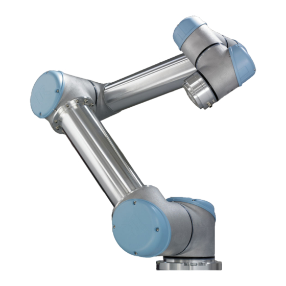
2.1. Introduction 2.1.1 The Robot The robot itself is an arm composed of extruded aluminum tubes and joints. The joints are named A:Base, B:Shoulder, C:Elbow and D,E,F:Wrist 1,2,3. The Base is where the robot is mounted, and at the other end (Wrist 3) the tool of the robot is attached. -
Page 15: Risk Assessment
Use proper lifting equipment. All regional and national guidelines for lifting shall be fol- lowed. Universal Robots cannot be held responsible for any damage caused by transportation of the equipment. Make sure to mount the robot according to the mounting instructions in section 2.5. -
Page 16: Initializing The Robot
2.3. Turning On and Off Figure 2.1: The initialization screen ’Start’. When a robot is started, a noise can be heard as the brakes unlock. After the robot has powereded up, it needs to be initialized before it can begin to perform work. -
Page 17: Quick Start, Step By Step
2.4. Quick start, Step by Step Shutting down by pulling the power cord out of the wall socket may cause corruption of the robot’s file system, which may result in robot malfunction. 2.4 Quick start, Step by Step To quickly set up the robot, perform the following steps: 1. -
Page 18: Mounting Instructions
2.5.1 The Workspace of the Robot The workspace of the UR5 robot extends to 850 mm from the base joint. The workspace of the robot is shown in figure 2.2. It is important to consider the cylindrical volume directly above and directly below the robot base when a... -
Page 19: Mounting The Robot
2.5. Mounting Instructions Front Tilted Figure 2.2: The workspace of the robot. The robot can work in an approxi- mate sphere (Ø170cm) around the base, except for a cylindrical volume directly above and directly below the robot base. mounting place for the robot is chosen. Moving the tool close to the cylindrical volume should be avoided if possible, because it causes the robot joints to move fast even though the tool is moving slowly, causing the robot to work inefficiently and the conduction of the risk assessment to be difficult. - Page 20 2.5. Mounting Instructions Surface on which the robot is fitted. It should be flat within 0.05mm Outer diameter of robot mounting flange Cable exit 132 ±0,5 Figure 2.3: Holes for mounting the robot, scale 1:1. Use 4 M8 bolts. All mea- surements are in All Rights Reserved...
-
Page 21: Mounting The Tool
2.5. Mounting Instructions 2.5.3 Mounting the Tool The robot tool flange has four holes for attaching a tool to the robot. A drawing of the tool flange is shown in figure 2.4. DANGER: 1. Make sure the tool is properly and securely bolted in place. - Page 22 2.5. Mounting Instructions Figure 2.4: The tool output flange, ISO 9409-1-50-4-M6. This is where the tool is mounted at the tip of the robot. All measures are in All Rights Reserved...
- Page 23 2.5. Mounting Instructions Parameter Unit Input voltage External fuse Input frequency Stand-by power Nominal operating power *NOTE: The fuse shall not be higher than the lowest current rating of the specific country plug and socket. Use the screw connection marked with earth symbol inside the controller box when potential equalization with other machinery is required.
- Page 24 2.5. Mounting Instructions DANGER: 1. Lockout and tagout all power for the complete robot installation during service. Other equipment shall not supply voltage to the robot I/O when the system is locked out. 2. Make sure that the robot is grounded correctly (Electrical connection to earth).
-
Page 25: Electrical Interface
Chapter 3 Electrical Interface 3.1 Introduction The robot is a machine that can be programmed to move a tool around in the robots workspace. Often, it is desired to coordinate robot motion with nearby machines or equipment on the tool. The most straightforward way to achieve this is often by using the electrical interface. - Page 26 Very high signal levels or excessive exposure can damage the robot permanently. EMC problems are found to happen usually in welding processes and are normally prompted by error messages in the log. Universal Robots cannot be held responsible for any damages caused by EMC problems.
-
Page 27: The Safety Interface
3.2. The Safety Interface 3.2 The Safety Interface Inside the controller box there is a panel of screw terminals. The leftmost part, in black above, is the safety interface. The safety interface can be used to connect the robot to other machinery or protective equipment, to make sure the robots stops in certain situations. - Page 28 3.2. The Safety Interface The Simplest Emergency Stop Configuration The simplest configuration is to use the internal emergency stop button as the only component to generate an emergency stop. This is done with the configuration shown above. This configuration is the default when the robot leaves the factory, and thereby the robot is ready to operate.
- Page 29 3.2. The Safety Interface Electric Specifications A simplified internal schematic of circuitry is shown below. It is important to no- tice that any short circuit or lost connection will lead to a safe stop, as long as only one error appears at a time. Failure and abnormal behavior of relays and power supplies results in an error message in the robot log and prevents the robot from powering up.
-
Page 30: The Safeguard Interface
3.2. The Safety Interface 3.2.2 The Safeguard Interface Test Output A [TA] Test Output B [TB] Safeguard Stop Input A (Positive) [SA] Safeguard Stop Input B (Negative) [SB] Automatic continue after safeguard stop Reset safeguard stop +24V supply connection for safety devices [24V] 0V supply connection for safety devices [GND]... -
Page 31: Automatic Continue After Safeguard Stop
3.2. The Safety Interface Connecting a reset button How to connect a reset button is shown above. It is not allowed to have a permanently pushed reset button. If the reset button is stuck a safeguard stop is generated and an error message will appear on the log screen. 3.2.3 Automatic continue after safeguard stop The safeguard interface can reset itself when a safeguard stop event is gone. -
Page 32: Controller I/O
3.3. Controller I/O Parameter Unit 24V Voltage tolerance -15% +20% Current available from 24V supply Overload protection [TA-TB][A ][R ] Voltage 10.5 12.5 [TA-TB][A ][R ] Current [TA-TB][A ][R ] Current protection [SA-SB] Input voltage [SA-SB] Guaranteed OFF if [SA-SB] Guaranteed ON if [SA-SB] Guaranteed OFF if [SA-SB] ON Current (10-30V) [A ][R ] Input voltage... -
Page 33: Digital Outputs
3.3. Controller I/O Electrical specifications of the internal power supply Parameter Unit Internal 24V voltage tolerance -15% +20% Current from internal 24V supply Overload protection External power supply voltage Note that the safeguard (yellow) 24V connections are sourced by the same internal 24V power supply as the 24V connections of the normal I/O, and that the maximum of 1.2 A is for both power sources together. -
Page 34: Digital Inputs
3.3. Controller I/O This example illustrates how to turn on a load. Load Controlled by Digital Output, External Power If the available current from the internal power supply is not enough, simply use an external power supply, as shown above. 3.3.2 Digital Inputs Parameter Unit... -
Page 35: Analog Outputs
3.3. Controller I/O Signal Communication with other Machinery or PLCs If communication with other machinery or PLCs is needed they must use pnp technology. Remember to create a common GND connection between the different interfaces. An example where two UR robots (A and B) are communi- cating with each other is illustrated above. -
Page 36: Analog Inputs
3.3. Controller I/O If the controlled equipment does not take a differential input, an alternative solution can be made as shown above. This solution is not very good in terms of noise, and can easily pick up disturbing signals from other machinery. Care must be taken when the wiring is done, and it must be kept in mind that disturbing signals induced into analog outputs may also be present on other analog I/O. -
Page 37: Tool I/O
3.4. Tool I/O Using Analog Inputs, Differential Current Input When longer cables are used, or if it is a very noisy environment, current based signals are preferred. Also, some equipment comes only with a current output. To use current as inputs, an external resistor is needed as shown above. The value of the resistor would normally be around 200 ohms, and the best result is accomplished when the resistor is close to the screw terminals of the controller box. -
Page 38: Digital Outputs
3.4. Tool I/O Color Signal 0V (GND) Gray 0V/12V/24V (POWER) Blue Digital output 8 (DO8) Pink Digital output 9 (DO9) Yellow Digital input 8 (DI8) Green Digital input 9 (DI9) White Analog input 2 (AI2) Brown Analog input 3 (AI3) This connector provides power and control signals for basic grippers and sen- sors, which may be present on a specific robot tool. -
Page 39: Digital Inputs
3.4. Tool I/O WARNING: 1. The digital outputs in the tool are not current limited and overriding the specified data can cause permanent dam- age to them. To illustrate clearly how easy it is to use digital outputs, a simple example is shown. - Page 40 3.4. Tool I/O Parameter Unit Input voltage in voltage mode -0.5 Input voltage in current mode -0.5 Input current in current mode -2.5 Input resistance @ range 0V to 5V kΩ Input resistance @ range 0V to 10V kΩ Input resistance @ range 4mA to 20mA Ω...
-
Page 41: Warranties
Warranty default becoming evident. Ownership of de- vices or components replaced by and returned to Universal Robots shall vest in Universal Robots. Any other claims resulting out of or in connection with the device shall be excluded from this Warranty. Nothing in this Warranty shall at- tempt to limit or exclude a Customer’s Statutory Rights, nor the manufacturer’s... - Page 42 4.2. Disclaimer All Rights Reserved...
-
Page 43: Applied Standards
Chapter 5 Applied standards 5.1 List of used standards Below is a list of applied documents and standards. - Page 44 5.1. List of used standards Applied EU directives 2006/42/EC Machinery Directive 2004/108/EC EMC Directive 2002/95/EC RoHS Directive 2002/96/EC WEEE Directive Applied harmonized standards ISO 13849-1:2006 (Under applied EU directives) ISO 13849-2:2003 ISO 10218-1:2006 (Partly) ISO 10218-1:2011 (Partly) ISO 10218-2:2011 (Partly) ISO 13850:2006 ISO 12100:2010 ISO 3745:2003...
-
Page 45: A Euromap67 Interface
This manual is intended for the integrator. It contains important information re- garding integration, programming, understanding and debugging. Abbreviations used in this document are explained below. Abbreviation Meaning Universal Robots Controller Box Injection Moulding Machine Moulding Area Free A, B, C, ZA, ZB and ZC... -
Page 46: Euromap67 Standard
IMM. Failure to integrate the robot and IMM in a safe way might cause death, serious injury or damage to the machines. Universal Robots cannot be held responsible for any damage caused by an IMM (E.g. -
Page 47: Robot And Imm Integration
A.2. Robot and IMM integration A.2 Robot and IMM integration The following subsections contain important information for the integrator. A.2.1 Emergency stop and safeguard stop The emergency stop signals are shared between the robot and the IMM. This means that a robot emergency stop also emergency stop the IMM and vice versa. -
Page 48: Mounting The Robot And Tool
A.2. Robot and IMM integration A.2.3 Mounting the robot and tool Before constructing a tool and a mounting surface, the integrator must consider how joint 4 (wrist 2) is orientated during pick and place. Joint 1, 2 and 3 has parallel axes and if joint 4 orientates joint 5 to the left or to the right then joint 5 is parallel to the other three axes, which forms a singularity. -
Page 49: Gui
A.3. GUI DANGER: 1. Make sure the E12 - E67 converter conforms to the eu- romap67 and euromap12 standards and that the safety functions are constructed with the correct performance level. Failure to follow this warning could result in serious injury or death as the safety stop function could be over- ridden. -
Page 50: I/O Overview And Troubleshooting
A.3. GUI The euromap67 program template is prepared for performing simple interac- tion with an IMM. By specifying only a few waypoints, and a pair of I/O actions, the robot is ready for handling the objects made by the IMM. The waypoints are: WP home position: The robot starting point for the procedure. - Page 51 A.3. GUI There are four frames on this screen, which are described separately below. Common for all are the two columns Robot and Machine, which respectively shows buttons for controlling output signals, and indicators for showing state of input signals. The (normal) state of the signals at startup, is that they are all low, except for the 24V signals, and the robot output Automatic Mode which is active-low and therefore set high per default.
-
Page 52: Program Structure Functionality
A.3. GUI high under the condition that the electrical supervision signal of the mould area (possible with use of light guard, as explained above), and the MAF signal from the software are both high. The MAF signal from software can be controlled by the respective button. - Page 53 A.3. GUI Startup Check Intended for use once in the beginning of a robot program, to make sure the robot and machine are set up correctly before moulding is started. Use the checkboxes to enable/disable individual steps. Free to Mould Used for signalling the IMM that it is allowed to start a moulding operation.
- Page 54 A.3. GUI CAUTION: 1. When this signal is activated, the robot shall be outside the mould, so that the mould can close without touching the robot. Wait for Item Intended for making the robot wait until an item is ready from the IMM. Use the checkboxes to enable/disable individual steps.
- Page 55 A.3. GUI Ejector Back Enables the movement of the ejector to its back position. Use the checkboxes to enable/disable individual steps. Core Pullers In Enables the movement of the core pullers to position 1. Which core pullers are used is selected from the drop down menu. Use the checkboxes to en- able/disable individual steps.
-
Page 56: I/O Action And Wait
A.3. GUI Core Pullers Out Enables the movement of the core pullers to position 2. Which core pullers are used is selected from the drop down menu. Use the checkboxes to en- able/disable individual steps. A.3.4 I/O action and wait As the robot digital outputs can be set by an Action node, so can also the eu- romap67 output signals. -
Page 57: Installing And Uninstalling The Interface
A.4. Installing and uninstalling the interface For advanced users, an output can be set to the value of a specified expres- sion. Such expression may contain both inputs, outputs, variables, etc., and can be used to obtain complex program functionality. Likewise, a Wait node can be set to wait until the value of an expression is true. -
Page 58: Uninstalling
A.5. Electrical characteristics Use 4 M4 8mm screws to screw on the interface. Use 4 M4 8mm screws to cover the empty holes. Click on the ribbon cable with the right orientation. Use some fixing pads to fix the ribbon cable. 3. -
Page 59: Emergency Stop, Safety Devices And Maf Signals
A.5. Electrical characteristics Parameter Unit 24V Voltage tolerance -15% +20% Current available from 24V supply Overload protection [MAF-MAF] Voltage when disconnected 12.5 [MAF-MAF] Current when connected [MAF-MAF] Protection against wrong connection [MAF-MAF] Protection against wrong connection NOTE: The ”MAF light guard interface” signals are not galvanically isolated from the shield of the controller box. - Page 60 A.5. Electrical characteristics to IEC 60664-1 and EN 60664-1, pollution degree 2, overvoltage category II. The outputs are constructed in compliance with all three types of digital inputs de- fined in IEC 61131-2 and EN 61131-2, and with all requirements for digital outputs of the same standards.
-
Page 61: B Certifications
Appendix B Certifications... - Page 62 All Rights Reserved...
Need help?
Do you have a question about the UR5 and is the answer not in the manual?
Questions and answers