Universal Robots UR5 Service Manual
With cb3-controller
Hide thumbs
Also See for UR5:
- Service manual (238 pages) ,
- User manual (223 pages) ,
- Original instructions manual (193 pages)

Related Manuals for Universal Robots UR5


Summary of Contents for Universal Robots UR5
- Page 1 Service Manual Revision UR5_en_3.0.2 Robot: UR5 with CB3-controller valid from robot s/n 2014350001...
-
Page 2: Table Of Contents
Contents General information ..........................4 1.1 Purpose ..............................4 1.2 Company details ............................5 1.3 Disclaimer ..............................5 Preventive Maintenance ........................... 6 2.1 Controller ..............................6 2.1.1 Inspection plan, Safety Functions ..................... 6 2.1.2 Visual inspection ..........................6 2.1.3 Cleaning and replacement of filters ....................7 2.2 Robot arm .............................. - Page 3 3.2.6 Replacement of 12V power supply ....................57 3.2.7 Replacement of current distributor....................58 Software ..............................60 4.1 Update software ............................ 60 4.2 Update joint firmware ........................... 62 4.3 Using Magic files ............................ 65 Troubleshooting ............................66 5.1 Error codes............................. 66 5.2 Error phenomena ..........................
-
Page 4: General Information
However any improper use of robot can potentially cause failures on the robot. For example, the robot may have been overloaded on an overrun or it may have been dropped on the floor when relocating or have run with a load not recommended by Universal Robots. Any improper use of the robot will invalidate the guarantee. -
Page 5: Company Details
Fax +45 38 79 89 89 1.3 Disclaimer The information contained herein is the property of Universal Robots A/S and shall not be reproduced in whole or in part without prior written approval of Universal Robots A/S. The information herein is subject to change without notice and should not be construed as a commitment by Universal Robots A/S. -
Page 6: Preventive Maintenance
2. Preventive Maintenance 2.1 Controller 2.1.1 Inspection plan, Safety Functions At least once in a year, the correct functioning of all safety functions should be tested. 2.1.2 Visual inspection Disconnect power cable from controller. Open cabinet door. ... -
Page 7: Cleaning And Replacement Of Filters
2.1.3 Cleaning and replacement of filters Controller box contains two filters, one on each side of controller. Remove filters from controller box and clean them thoroughly using compressed air. » Replace filters if necessary. All rights reserved Servicemanual_UR5_en_rev3.0.2... -
Page 8: Robot Arm
2.2 Robot arm 2.2.1 Visual inspection Move robot arm to HOME position (if possible). Turn off and disconnect power cable from controller. Inspect cable between controller and robot arm for any damages. Inspect flat rings for wear and damages. »... -
Page 9: Service And Replacement Of Parts
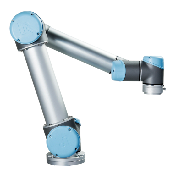
3. Service and Replacement of parts 3.1 Robot arm 3.1.1 Robot arm configuration Tool flange Wrist 3 Wrist 1 Wrist 2 Lower arm Elbow Upper arm Base Shoulder Baseplate All rights reserved Servicemanual_UR5_en_rev3.0.2... -
Page 10: Brake Release
3.1.2 Brake release If required, the brake on a joint can be released without power connected. IMPORTANT NOTICE: Before releasing a brake it is extremely important to dismount any dangerous tooling for avoiding any hazardous situations. If releasing the brake on Base joint, Shoulder joint or Elbow joint, it is important to make proper mechanical support prior to releasing the brake. -
Page 11: Replacement Of Base Plate
3.1.3 Replacement of base plate How to replace base plate Move robot to a comfortable position for replacing the base. If necessary dismount entire robot arm from work cell and place arm on solid surface. Shut down the controller. ... - Page 12 Slide the grey Teflon ring apart. 10 screws become visible, 5 on each side of joint. Untighten gently the screw with a 7 mm. open-ended spanner about two full rounds, approximately 3 mm. for each screw. Pull the base plate and Base joint apart and gently twist the two parts in opposite directions around 10 mm.
- Page 13 Replace base plate and reconnect wires according to illustration: Gently insert base plate with screws and washers into the Base joint. Make sure the washers are fully inserted and located on the correct side (this is important) before gently twisting the base plate and Base joint in opposite directions until a mechanical stop is met.
-
Page 14: Replacement Of Base Joint
3.1.4 Replacement of Base joint How to replace Base joint Move robot to a comfortable position for replacing the joint. If necessary dismount entire robot arm from work cell and place arm on solid surface. Shut down the controller. ... - Page 15 Gently remove black flexible flat ring between Base and Shoulder with a tiny screwdriver or similar tool and twist it around the joint housing. Slide the grey Teflon ring apart. 10 screws become visible, 5 on each side of joint. Untighten gently the screw with a 7 mm.
- Page 16 • Pull away the Base joint from Shoulder joint. Replace Base joint and gently insert Base joint with screws and washers into the Shoulder joint. Make sure the washers are fully inserted and located on the correct side (this is important) before gently twisting the Base joint and Shoulder joint in opposite directions until a mechanical stop is met.
-
Page 17: Replacement Of Shoulder Joint
3.1.5 Replacement of Shoulder joint How to replace Shoulder joint Move robot to a comfortable position for replacing the joint. If necessary dismount entire robot arm from work cell and place arm on solid surface. Shut down the controller. ... - Page 18 Unmount screws around the upper arm as indicated on the illustration: • Pull away the Shoulder joint from upper arm. Replace Shoulder joint and mount screws into shoulder joint. Tighten screws lightly, then tighten in cross order with 3.0Nm. ...
-
Page 19: Replacement Of Elbow Joint
3.1.6 Replacement of Elbow joint How to replace Elbow joint Move robot to a comfortable position for replacing the joint. If necessary dismount entire robot arm from work cell and place arm on solid surface. Shut down the controller. ... - Page 20 Pull Elbow joint and lower arm apart and gently twist the two parts in opposite directions around 10 mm. until a mechanical stop is met (holes are keyhole-type). • Pull away the Elbow joint from lower arm. Disconnect wires between Elbow joint and lower arm 1 x red wire = 48V DC 1 x black wire...
- Page 21 For separating upper arm from Elbow joint, remove blue lid on Shoulder joint. Disconnect wires between Elbow joint and upper arm 1 x red wire = 48V DC 1 x black wire = GND Black connector = bus cable ...
- Page 22 • Pull away the Elbow joint from upper arm. Replace Elbow joint and gently insert lower arm into the Elbow joint. Tighten the 10 screws lightly, then tighten in cross order with respectively 3.0Nm. Slide the grey Teflon ring in place and gently put back the flat ring on top of the Teflon ring. ...
-
Page 23: Replacement Of Wrist 1 Joint
3.1.6 Replacement of Wrist 1 joint How to replace Wrist 1 joint Move robot to a comfortable position for replacing the joint. If necessary dismount entire robot arm from work cell and place arm on solid surface. Shut down the controller. ... - Page 24 With a screw driver or similar tool, gently remove nylon ring as illustrated 8 screws become visible, 4 on each side of joint. Untighten gently the screws with a 5.5 mm. open-ended spanner about two full rounds, approximately 3 mm. for each screw. ...
- Page 25 Remove blue lid on Wrist 2 joint. Disconnect wires between Wrist 1 joint and Wrist 2 joint 1 x red wire = 48V DC 1 x black wire = GND Black connector = bus cable Gently remove black flexible flat ring between Wrist 1 and Wrist 2 with a tiny screwdriver or similar tool and twist it around the joint housing.
- Page 26 Slide the grey Teflon ring apart. 8 screws become visible, 4 on each side of joint. Untighten gently the screws with a 5.5 mm. open-ended spanner about two full rounds, approximately 3 mm. for each screw. Pull Wrist 1 joint and Wrist 2 joint apart and gently twist the two parts in opposite directions around 8 mm.
- Page 27 Replace Wrist 1 and gently insert Wrist 1 joint with screws and washers into Wrist 2 joint. Make sure the washers are fully inserted and located on the correct side (this is important) before gently twisting Wrist 1 joint and Wrist 2 joint in opposite directions until a mechanical stop is met. ...
- Page 28 Gently insert Wrist 1 joint with screws and washers into the lower arm. Make sure the washers are fully inserted and located on the correct side (this is important) before gently twisting Wrist 1 joint and lower arm in opposite directions until a mechanical stop is met. ...
-
Page 29: Replacement Of Wrist 2 Joint
3.1.7 Replacement of Wrist 2 joint How to replace Wrist 2 joint Move robot to a comfortable position for replacing the joint. If necessary dismount entire robot arm from work cell and place arm on solid surface. Shut down the controller. ... - Page 30 Gently remove black flexible flat ring between Wrist 1 and Wrist 2 with a tiny screwdriver or similar tool and twist it around the joint housing. Slide the grey Teflon ring apart. 8 screws become visible, 4 on each side of joint. Untighten gently the screws with a 5.5 mm.
- Page 31 • Pull away Wrist 1 joint from Wrist 2 joint. Wrist 1 joint and Wrist 2 joint has now been separated. Perform same procedure for separating Wrist 2 joint and Wrist 3 joint and proceed when done. Replace Wrist 2 and gently insert Wrist 2 joint with screws and washers into Wrist 1 joint. ...
- Page 32 Mount blue lid on Wrist 2 joint and tighten with 0.5Nm. Wrist 1 joint and Wrist 2 joint has now been assembled. Perform same procedure for assembling Wrist 2 joint and Wrist 3 joint. Proceed to chapter 3.1.11 Joint calibration for calibrating the joint.
-
Page 33: Replacement Of Wrist 3 Joint
3.1.8 Replacement of Wrist 3 joint How to replace Wrist 3 joint Move robot to a comfortable position for replacing the joint. If necessary dismount entire robot arm from work cell and place arm on solid surface. Shut down the controller. ... - Page 34 Gently remove black flexible flat ring between Wrist 2 and Wrist 3 with a tiny screwdriver or similar tool and twist it around the joint housing. Slide the grey Teflon ring apart. 8 screws become visible, 5 on each side of joint. Untighten gently the screws with a 5.5 mm.
- Page 35 • Pull away Wrist 2 joint from Wrist 3 joint. Wrist 2 joint and Wrist 3 joint has now been separated. For separating Wrist 3 joint from tool flange, consult chapter 3.1.9 Replacement of tool flange. Replace Wrist 3 and gently insert Wrist 3 joint with screws and washers into Wrist 2 joint. ...
- Page 36 Mount blue lid on Wrist 3 joint and tighten with 0.5Nm. Wrist 2 joint and Wrist 3 joint has now been assembled. For assembling Wrist 3 joint and tool flange, consult chapter 3.1.9 Replacement of tool flange. ...
-
Page 37: Replacement Of Tool Flange
3.1.9 Replacement of tool flange How to replace tool flange Move robot to a comfortable position for replacing the tool flange. If necessary dismount entire robot arm from work cell and place arm on solid surface. Shut down the controller. ... - Page 38 Slide the grey Teflon ring apart. 8 screws become visible, 5 on each side of joint. Untighten gently the screws with a 5.5 mm. open-ended spanner about two full rounds, approximately 3 mm. for each screw. Pull the tool flange and Wrist 3 joint apart and gently twist the two parts in opposite directions around 8 mm.
- Page 39 Replace tool flange and reconnect connectors as illustrated. Replace tool and reconnect wires correctly. Gently insert tool flange with screws and washers into the Wrist 3 joint. Make sure the washers are fully inserted and located on the correct side (this is important) before gently twisting the tool flange and Wrist 3 joint in opposite directions until a mechanical stop is met.
-
Page 40: Torque Values
3.1.10 Torque values UR5 torque values CONNECTION TORQUE HEAD SIZE BASE PLATE J0 BASE 3.0Nm 7 mm. [J0] BASE J[1] Shoulder 3.0Nm 7 mm. [J1] SHOULDER LOWER ARM 3.0Nm 7 mm. LOWER ARM [J2] ELBOW 3.0Nm 7 mm. [J2] ELBOW HIGHER ARM 3.0Nm... -
Page 41: Joint Calibration
3.1.11 Joint calibration After replacement of joint it is required to calibrate the new joint in order to find the correct zero position of joint. Instruction for calibrating a joint Jog robot to HOME position Illustration shows the HOME position, which is defined as zero position of all joints. ... - Page 42 Enter password lightbot and press OK. lightbot You are now in Expert Mode, press Low Level Control. Select Power On/Off tab and press Turn power on for enabling power to motors. All rights reserved Servicemanual_UR5_en_rev3.0.2...
- Page 43 Select General tab, and select the desired joint by either using the dropdown list or directly press on the joint state line. Press Arm current joint for releasing the brake on the selected joint. Select Move tab and press either Up or Down for the joint to find its index mark. For every time the button is pressed, the velocity of joint will be increased.
- Page 44 Await that state of the joint changes to OK, then press STOP. Index mark has now been found (index mark is not the same position as zero position). Use the Up and Down buttons for navigating the joint to the correct zero position according to the following illustrations.
- Page 45 Zero position illustrations Base: Shoulder, Elbow, Wrist 1: Base zero position is aligned to Shoulder, Elbow and Wrist 1 zero positions are connector in back of robot base. Vertical aligned (if Base if horizontal). Make sure that base of robot is positioned horizontal, use leveler for aligning joints.
- Page 46 Select Calibration tab and press Zero current joint position for calibrating the joint. Press Back for exiting Low Level Control. Back in Expert Mode, press Return to Normal. Verify zero position by moving the robot to HOME. If not satisfied with the zero position, perform the procedure once again.
-
Page 47: Controller
3.2 Controller 3.2.1 Handling ESD-sensitive parts To prevent damage to ESD-sensitive parts, follow the instructions below in addition to all the usual precautions, such as turning off power before removing logic cards: Keep the ESD-sensitive part in its original shipping container (a special "ESD bag") until the part is ready to be installed. -
Page 48: Replacement Of Motherboard
3.2.2 Replacement of motherboard Take care of ESD handling 3.2.1 Handling ESD-sensitive parts How to replace motherboard in Controller box Shut down the controller and disconnect the power cable, open the controller cabinet and loosen the 3 Torx screws ... - Page 49 Disconnect cable connections from motherboard: 2x RJ45 network cables Black USB cable DVI-cable Black cable for RS232-connection White plug with white, brown, yellow and green wires Remove the 4 screws of the 2 holding brackets. Replace Motherboard with new. ...
- Page 50 Insert the 6 cables in correct positions. Re-install Flash card and RAM block. Carefully put back the grey alu cover plate, make sure to mount it correct and fix it with the 5 screws. Connect power and verify that teach pendant works properly. All rights reserved Servicemanual_UR5_en_rev3.0.2...
-
Page 51: Replacement Of Safety Control Board
3.2.3 Replacement of Safety Control Board Take care of ESD handling 3.2.1 Handling ESD-sensitive parts How to replace Safety Control Board in Controller box Shut down the controller and disconnect the power cable, open the controller cabinet and loosen the 5 Torx screws ... - Page 52 Carefully remove all plugs and connectors (it is recommended to mark the cable positions or take a picture of them). Remove 13 screws holding the Safety Control Board. Replace Safety Control Board with new and tighten the 15 screws to hold the board ...
-
Page 53: Replacement Of Teach Pendant
3.2.4 Replacement of teach pendant Take care of ESD handling 3.2.1 Handling ESD-sensitive parts How to replace Teach Pendant on Controller Note: use the same procedure for power down and removing the alu cover plates as in chapter 3.2.2 Replacement of motherboard 3.2.3 Replacement of Safety Control Board ... -
Page 54: Replacement Of 48V Power Supply
3.2.5 Replacement of 48V power supply Take care of ESD handling 3.2.1 Handling ESD-sensitive parts How to replace 48V power supply in Controller box Note: use the same procedure for power down and removing the alu cover plates as in chapter 3.2.2 Replacement of motherboard 3.2.3 Replacement of Safety Control Board... - Page 55 Gently take out the controller module from the Controller box without disconnecting the robot cable and power cable. Power supplies are located in the rack under the controller module, the two 48V power supplies are the lower ones in the rack. Before dismounting the 48V power supply, mark and disconnect the cables from that supply.
- Page 56 Replace 48V power supply with new. Reconnect the wires for the 48V power supply. Re-install Controller module in reverse order and connect the 2 wires for the fan and cables for the teach pendant. Carefully put back the grey alu cover plate, make sure to mount it correct and fix it with the 5 screws.
-
Page 57: Replacement Of 12V Power Supply
3.2.6 Replacement of 12V power supply Take care of ESD handling 3.2.1 Handling ESD-sensitive parts How to replace 12V power supply in Controller box Note: use the same procedure for power down and removing the alu cover plate and cables for teach pendant as in chapter 3.2.4 Replacement of teach pendant For replacing the 12V power supply follow exactly the same steps as for the procedure in chapter... -
Page 58: Replacement Of Current Distributor
3.2.7 Replacement of current distributor Take care of ESD handling 3.2.1 Handling ESD-sensitive parts How to replace current distributor in Controller box Note: use the same procedure for power down and removing the alu cover plate and cables for teach pendant as in chapter3.2.4 Replacement of teach pendant For replacing the current distributor follow exactly the same steps as for the procedure in chapter... - Page 59 Replace current distributor with new. Reconnect the wires for the current distributor. Re-install Controller module in reverse order and connect the 2 wires for the fan and cables for the teach pendant. Carefully put back the grey alu cover plate, make sure to mount it correct and fix it with the 5 screws.
-
Page 60: Software
When updating software on robot with older version, it is required to install each update in sequence. If it ain’t broken, don’t fix it: If a robot is operating in an existing application, Universal Robots do not recommend updating software, unless the use of new functions in a newer software release is required for this application. - Page 61 Press button SETUP Robot. In left side menu, select UPDATE Robot. Press button Search for searching after software update on USB-stick. Mark the found software update and press UPDATE. Press YES for updating the software. ...
-
Page 62: Update Joint Firmware
When updating firmware it is strictly forbidden to turn off controller or to remove cable between controller and robot arm during update. Universal Robots can be no means be held responsible for any failed update caused by improper operation. Instruction for updating firmware Prior to updating firmware, it is required to update the robot software. - Page 63 Enter password lightbot and press OK. lightbot You are now in Expert Mode, press Low Level Control. Select the Firmware tab, mark All joints and press UPDATE firmware. Firmware update is being processed, await message that robot firmware updated successfully. It is strictly forbidden to turn off controller during this update.
- Page 64 Back in Expert Mode, press Return to Normal. Firmware has now been updated. All rights reserved Servicemanual_UR5_en_rev3.0.2...
-
Page 65: Using Magic Files
4.3 Using Magic files For easy backup, Universal Robots provides Magic files for automatic copy of data from controller to USB- stick. These files are available: Function: URmagic log file copies the entire log history file to USB-stick ... -
Page 66: Troubleshooting
5. Troubleshooting 5.1 Error codes Code Error description Explanation How to fix CODE_0 No error CODE_1 Outbuffer overflow error CODE_1A1 Buffer of stored warnings overflowed CODE_1A2 Outbuffer to RS485 overflowed (problem with PCs message) CODE_2 Inbuffer overflow error CODE_3 Processor overloaded error CODE_4 Broken communication CODE_4A1... - Page 67 problem with one or more joints CODE_4A14 Communication with joint 2 lost Serial communication problem with one or more joints CODE_4A15 Communication with joint 3 lost Serial communication problem with one or more joints CODE_4A16 Communication with joint 4 lost Serial communication problem with one or...
- Page 68 CODE_4A76 Lost package from tool Serial communication problem with one or more joints CODE_4A77 Lost package from uPA to joints CODE_4A78 Lost package from uPA to teach pendant CODE_4A79 Lost package from uPA to uPB CODE_4A80 Lost package from uPB CODE_4A81 Packet counter disagreement in packet from Primary Screen...
- Page 69 CODE_12 Unknown message error CODE_14 Debug message CODE_17 Inbuffer overflow in package from PC Communication Check ethernet error between Safety connection between Control Board and circuit boards Motherboard CODE_26 Motor Encoder index drift detected Joint mechanical Replace joint problem CODE_27 Calibration data is invalid or does not exist, selftest is needed! CODE_29...
- Page 70 CODE_39A105 Watchpoint fault: RAM-test task timeout CODE_39A106 Watchpoint fault: CalVal-test task timeout CODE_39A107 Watchpoint fault: ROM-test task timeout CODE_40 AD-Converter hit high limit joint EMC issue external Check grounding and or electronics shielding for EMC internal problems CODE_44 CRC check failure on primary bus Serial Check green 2-wire communication...
- Page 71 Installation the miscellaneous settings CODE_50A17 The Euromap67 interface does not respond Loose wire or Check the cable or incorrect safety change in the Safety configuration Configuration of the Installation the miscellaneous settings CODE_50A18 Warning, waiting for SafetySYS1 CODE_50A20 5V, 3V3 or ADC error (5V too high) CODE_50A21 5V, 3V3 or ADC error (5V too low) CODE_50A22...
- Page 72 CODE_53ATO , max is 600mA CODE_55 Safety system error Safety system Check Motherboard, malfunction Masterboard, Screenboard, Current distributor( Euromap, if installed ). Bypass safety connections to I/O- interface of Masterboard CODE_55A23 Safety relay error (minus connection) CODE_55A24 Safety relay error (plus connection) CODE_55A33 Safety relay error (a relay is stuck) CODE_55A34...
- Page 73 Safety Control Board and check that the flash card and robot match CODE_72A3 2 PSUs active, but we expect 1 (UR5) UR5 flash card in Check that the flash UR10 robot card and robot match CODE_73...
- Page 74 CODE_75A4 System error=malfunction or inconsistent calibration detected CODE_75A32 Signal lost =Misaligned readhead or damaged ring CODE_76 Joint encoder communication CRC error CODE_100 Robot changed mode Status warning, Check preceding errors general modus in log history change CODE_101 Real Robot Connected CODE_102 Real Robot not connected - Simulating Robot CODE_103...
- Page 75 CODE_191A9 Reduced mode output violation CODE_191A10 Safeguard stop output violation CODE_191A11 Emergency stop output violation CODE_191A12 Momentum limit violation CODE_191A13 Robot moving output violation CODE_191A14 Robot is not braking in stop mode CODE_191A15 Robot is moving in stop mode CODE_191A16 Robot did not stop in time CODE_191A17 Received a null vector for TCP orientation...
- Page 76 CODE_192A17 Safeguard stop output disagreement CODE_192A18 The other safety processor is in fault CODE_192A19 Emergency stop output disagreement CODE_192A20 SPI output error detected CODE_192A21 Momentum disagreement CODE_192A22 Robot moving output disagreement CODE_192A23 Wrong processor ID CODE_192A24 Wrong processor revision CODE_192A25 Potential brownout detected CODE_192A26 Emergency stop output disagreement...
- Page 77 CODE_194A8 Screen 2 CODE_194A9 Euromap 1 CODE_194A10 Euromap 2 CODE_195 Conveyor speed too high Conveyor speed Make sure that higher than robot is conveyor tracking is set able to run correct up CODE_196 MoveP speed too high Too high speed in Reduce speed or relation to blend increase blend radius in...
-
Page 78: Error Phenomena
5.2 Error phenomena 5.2.1 ControlBox: NO CONTROLLER displayed in Initializing ControlBox = NO CONTROLLER displayed at INITIALIZING screen Replace ethernet cable between motherboard Defective ethernet cable and Safety Control Board and verify problem is solved Replace Safety Control Board and verify problem Defective Safety Control is solved Board... -
Page 79: Cable Displayed During Power Up
5.2.2 NO CABLE displayed during power up NO CABLE displayed during power up > controller shuts off after few seconds Measure that 230V AC is present on power input Replace current distributor connector on 12V power supply Measure that 12V DC is present on 12V_IN Replace 12V power supply connector on Safety Control Board and diode marked 12V in top right corner of Safety Control... -
Page 80: Force Limit Protective Stop
5.2.3 Force limit protective stop Force Limit Protective Stop Payload and tcp settings in Installation\Mounting Adjust payload and tcp must correspond with actual tool. settings Are settings incorrect? Adjust center of mass using Is center of mass very different from tcp point? script code set_payload() (software v1.7 or newer) Are waypoints positioned very close to cylindrical... -
Page 81: Power On Failure In Initializing
5.2.4 Power on failure in Initializing If power turns off a few seconds after Robot Power is turned On in the Initializing window, there are many possible causes for this phenomenon. Most likely it is a control box failure or a communication failure with a joint or the tool. Control box failure Check log history for error messages and consult the section Error Codes for detailed explanation... - Page 82 Communication failure with a joint or the tool connector Check log history for error messages and consult the section Error Codes for detailed explanation Go to LOW LEVEL CONTROL in EXPERT MODE (consult chapter 4.2 for how to access EXPERT MODE) Unmount tool and check Go to tab POWER ON/OFF and press TURN...
- Page 83 Continued Go to tab POWER ON/OFF and press TURN Remove blue lid of joint and POWER ON. Does state of all joints J0-J5 switch check green comm. from BROKEN COMM. ERROR to READY? connector is fully inserted Does state of joint switch to READY? Communication ok to joints and tool Replace joint...
-
Page 84: Checklist After A Collision
5.2.5 Checklist after a collision Checklist after a collision Check log history for error messages and consult the section Error Codes for detailed explanation Stop robot program and eventually press the Emergency button prior to entering the work cell Visually inspect robot arm. Remove lid and inspect Are any parts visually damaged, like damages on parts inside of joint... -
Page 85: Schematic Drawing
5.3 Schematic drawing All rights reserved Servicemanual_UR5_en_rev3.0.2... -
Page 86: Spare Parts
Item no. Item designation Controller: 122905 Controller incl. Teach Pendant UR5 122900 Controller excl. Teach Pendant UR5 122091 Teach Pendant incl. Touch Screen & power cable UR5 & UR10 171021 Flash card 122600 Motherboard kit 172290 Safety Controlboard Kit 177002... -
Page 87: Tool Part List
6.2 Tool part list Item no. Item designation 109005 Tool kit UR5 (kit includes all of the below part no.’s) 109101 Spanner Hex 5.5mm 109102 Spanner Hex 7.0mm 109103 Screwdriver torx T10 109105 Torque wrench Hex 5.5mm Size 1 and Size 2 109106 Torque wrench Hex 7.0mm Size 3... -
Page 88: Packing Of Robot
7. Packing of robot Packing of robot and controller box for shipment Remove any external tooling and external electrical connections. Load program Put_into_box_ur5.urp and follow instructions while removing mounting bolts. While robot folds together, hold a piece of bubble wrap between Shoulder joint and wrists. Note: If robot cannot run or power is not available, it is possible to manually release the brakes for each joint individually and pack the robot accordingly. -
Page 89: Changelog
8. Changelog 8.1 Changelog Date Revision Action Changes 3. May 2014 UR5_en_3.0 Added Revision 3.0 released 19. June 2014 UR5_en_3.0.1 Changed Pictures and illustrations changed to match 3. gen. robot 29. July 2014 UR5_en_3.0.2 Changed Error codes, Spareparts changed to match 3. Gen robot and ESD handling added All rights reserved Servicemanual_UR5_en_rev3.0.2...
Need help?
Do you have a question about the UR5 and is the answer not in the manual?
Questions and answers