Table of Contents
Advertisement
Quick Links
Advertisement
Table of Contents

Related Manuals for Universal Robots UR3/CB3


Summary of Contents for Universal Robots UR3/CB3
- Page 1 Universal Robots UR3/CB3 Original instructions (en) US version...
- Page 3 Universal Robots UR3/CB3 Euromap67 Version 3.10 Original instructions (en) US Version...
- Page 4 The information contained herein is the property of Universal Robots A/S and shall not be reproduced in whole or in part without prior written approval of Universal Robots A/S. The information herein is subject to change without notice and should not be construed as a commitment by Universal Robots A/S.
- Page 5 Maximum Payload ......... . I-27 Version 3.10 UR3/CB3...
- Page 6 EMC Test Certificate ......... I-66 UR3/CB3 Version 3.10...
- Page 7 11.4 Welcome Screen ......... . . II-30 Version 3.10 UR3/CB3...
- Page 8 13.16 Log Tab ..........II-63 UR3/CB3 Version 3.10...
- Page 9 14.32 Structure Tab ..........II-115 Version 3.10 UR3/CB3...
- Page 10 18.4 I/O action and wait ......... III-21 UR3/CB3 viii Version 3.10...
- Page 11 20.4 Digital Outputs ..........III-28 Glossary III-29 Index III-31 Version 3.10 UR3/CB3...
- Page 12 UR3/CB3 Version 3.10...
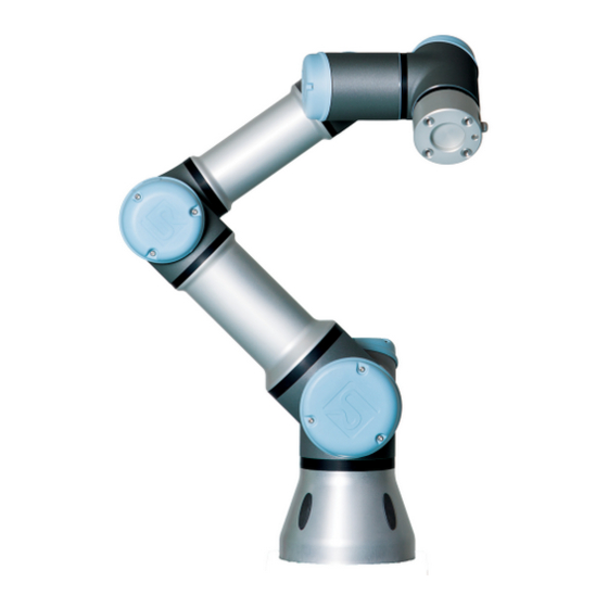
- Page 13 Preface Congratulations on the purchase of your new Universal Robots robot, UR3. The robot can be programmed to move a tool, and communicate with other machines using electri- cal signals. It is an arm composed of extruded aluminium tubes and joints.
- Page 14 UR robots, ensuring simple set-up, reliable operation, smooth user experience, and easy programming. You can also use the site to join the UR+ Devel- oper Program to access our new software platform which allows you to design more user-friendly products for UR robots. UR3/CB3 Version 3.10...
- Page 15 Part I Hardware Installation Manual...
- Page 17 Special attention shall be paid to text associated with warning symbols. NOTE: Universal Robots disclaims any and all liability if the robot (arm con- trol box and/or teach pendant) is damaged, changed or modified in any way. Universal Robots cannot be held responsible for any dam- ages caused to the robot or any other equipment due to programming errors or malfunctioning of the robot.
- Page 18 WARNING: This indicates a potentially hazardous situation which, if not avoided, could result in injury or major damage to the equipment. WARNING: This indicates a potentially hazardous hot surface which, if touched, could result in injury. UR3/CB3 Version 3.10...
- Page 19 This section contains some general warnings and cautions that can be repeated or explained in different parts of this manual. Other warnings and cautions are present throughout this manual. DANGER: You must install the robot and all electrical equipment according to the specifications and warnings found in chapters 4 and 5. Version 3.10 UR3/CB3...
- Page 20 11. Be aware of robot movement when using the teach pendant. 12. If determined by the risk assessment, do not enter the safety range of the robot or touch the robot when the system is in op- eration. UR3/CB3 Version 3.10...
- Page 21 It is also recom- mended to test the robot program using temporary waypoints outside the workspace of other machines. 2. Do not expose the robot to permanent magnetic fields. Very strong magnetic fields can damage the robot. Version 3.10 UR3/CB3...
- Page 22 UR3/CB3 Version 3.10...
- Page 23 (e.g. an enabling device to protect the operator during set-up and programming). Universal Robots identifies the potential significant hazards listed below as hazards that must be considered by the integrator. Note: Other significant hazards can be present in a specific robot installation.
- Page 24 2. If the brake is released manually, gravitational pull can cause the robot arm to fall. Always support the robot arm, tool/end effector and work item when releasing the brake. UR3/CB3 I-10 Version 3.10...
- Page 25 1.9 Movement With and Without Drive Power Version 3.10 I-11 UR3/CB3...
- Page 26 1.9 Movement With and Without Drive Power UR3/CB3 I-12 Version 3.10...
- Page 27 The robot has a number of safety-related functions that can be used to limit the movement of its joints and of the robot Tool Center Point (TCP). The TCP is the center point of the output flange with the addition of the TCP offset. The limiting safety-related functions are: Version 3.10 I-13 UR3/CB3...
- Page 28 Violations of limits will hence only occur in exceptional cases. Nevertheless, if a limit is violated, the safety system issues a Stop Category 0. Stop Categories are according to IEC 60204-1, see Glossary for more details. UR3/CB3 I-14 Version 3.10...
- Page 29 Reduced. Safety limits can be configured for each of these two modes. Reduced mode is active when the robot TCP is positioned beyond a Trigger Reduced mode plane or when triggered by a safety in- put. Reduced mode can be triggered either by using a plane or by using an input. Version 3.10 I-15 UR3/CB3...
- Page 30 PolyScope (see part II “PolyScope Manual”). The safety limits of Recovery mode are: Limiting Safety Function Limit Joint speed 30 / TCP speed TCP force 100 N Momentum kg m Power 80 W The safety system issues a Stop Category 0 if a violation of these limits appears. UR3/CB3 I-16 Version 3.10...
- Page 31 2. If a joint is moving, its speed is monitored to never be higher than the speed obtained by con- stantly decelerating from the maximum joint speed limit for Normal mode to 0 in 500 ms. Version 3.10 I-17 UR3/CB3...
- Page 32 1000 ms 1250 ms System Emergency Stop 250 ms 1000 ms 1250 ms Safeguard Stop 250 ms 1000 ms 1250 ms 2.5.2 Safety-related Electrical Outputs The table below gives an overview of the safety-related electrical outputs: UR3/CB3 I-18 Version 3.10...
- Page 33 If a safety output is not set properly, the safety system issues a Stop Category 0, with the following worst-case reaction times: Safety Output Worst Case Reaction Time System Emergency Stop 1100 ms Robot Moving 1100 ms Robot Not Stopping 1100 ms Reduced Mode 1100 ms Not Reduced Mode 1100 ms Version 3.10 I-19 UR3/CB3...
- Page 34 2.5 Safety-related Electrical Interfaces UR3/CB3 I-20 Version 3.10...
- Page 35 Use proper lifting equipment. All regional and national guidelines for lifting shall be followed. Universal Robots cannot be held responsible for any damage caused by transportation of the equipment. 2. Make sure to mount the robot according to the mounting in- structions in chapter 4.
- Page 36 UR3/CB3 I-22 Version 3.10...
- Page 37 Mount the robot on a sturdy surface strong enough to withstand at least ten times the full torque of the base joint and at least five times the weight of the robot arm. Furthermore the surface shall be Version 3.10 I-23 UR3/CB3...
- Page 38 Teach Pendant The teach pendant can be hung on a wall or on the control box. Extra brackets for mounting the teach pendant can be bought. Make sure that no one can trip over the cable. UR3/CB3 I-24 Version 3.10...
- Page 39 4.3 Mounting Figure 4.1: Holes for mounting the robot. Use four M6 bolts. All measurements are in mm. Version 3.10 I-25 UR3/CB3...
- Page 40 A wet control box could cause death. 2. The control box and teach pendant must not be exposed to dusty or wet environments that exceed IP20 rating. Pay special atten- tion to environments with conductive dust. UR3/CB3 I-26 Version 3.10...
- Page 41 4.3. The center of gravity offset is defined as the distance between the center of the tool output flange and the center of gravity. Payload [kg] Center of gravity offset [mm] Figure 4.3: Relationship between the maximum allowed payload and the center of gravity offset. Version 3.10 I-27 UR3/CB3...
- Page 42 4.4 Maximum Payload UR3/CB3 I-28 Version 3.10...
- Page 43 Keep the two channels separate so that a single fault cannot lead to loss of the safety function. 3. Some I/O inside the control box can be configured for either normal or safety-related I/O. Read and understand the com- plete section 5.3. Version 3.10 I-29 UR3/CB3...
- Page 44 EMC problems are found to happen usually in welding processes and are normally prompted by error mes- sages in the log. Universal Robots cannot be held responsible for any damages caused by EMC problems. 2. I/O cables going from the control box to other machinery and factory equipment may not be longer than 30m, unless extended tests are performed.
- Page 45 It is possible to power the digital I/O from an internal 24V power supply or from an external power source by configuring the terminal block called Power. This block consists of four terminals. The Version 3.10 I-31 UR3/CB3...
- Page 46 Leakage current [COx / DOx] Function Type [COx / DOx] IEC 61131-2 Type [COx / DOx] Digital Inputs Voltage [EIx/SIx/CIx/DIx] OFF region [EIx/SIx/CIx/DIx] ON region [EIx/SIx/CIx/DIx] Current (11-30V) [EIx/SIx/CIx/DIx] Function Type [EIx/SIx/CIx/DIx] IEC 61131-2 Type [EIx/SIx/CIx/DIx] UR3/CB3 I-32 Version 3.10...
- Page 47 It is possible to use the configurable I/O to set up additional safety I/O functionality, e.g. emer- gency stop output. Configuring a set of configurable I/O for safety functions are done through the GUI, see part II. Some examples of how to use safety I/O are shown in the following subsections. Version 3.10 I-33 UR3/CB3...
- Page 48 It is often desired to set up a common emergency stop circuit when the robot is used together with other machines. By doing so, the operator does not need to think about which emergency stop buttons to use. UR3/CB3 I-34 Version 3.10...
- Page 49 The configurable I/O can be used to setup a reset button outside the door, to reactivate robot motion. Another example where automatic resume can be appropriate is when using a safety mat or a safety-related laser scanner, see below. Version 3.10 I-35 UR3/CB3...
- Page 50 The reset button must be a two channel type. In this example the I/O configured for reset is “CI0-CI1”, see below. Safety Configurable7Inputs 5.3.2.6 Three-Position Enabling Device The illustration below shows how to connect a Three-Position Enabling Device. See section 10.13.1 for more about Three-Position Enabling Device. UR3/CB3 I-36 Version 3.10...
- Page 51 5.3 Controller I/O NOTE: The Universal Robots safety system does not support multiple Three- Position Enabling Devices. NOTE: The two input channels for the Three-Position Enabling Device input have a disagreement tolerance of 1 second. 5.3.3 General purpose digital I/O This section describes the general purpose 24V I/O (Gray terminals) and the configurable I/O...
- Page 52 “Power”. • Use of equipment that works in current mode. Current signals are less sensitive to interfer- ences. Input modes can be selected in the GUI, see part II. The electrical specifications are shown below. UR3/CB3 I-38 Version 3.10...
- Page 53 5.3.6.1 Using an analog output Below is an example of how to control a conveyor belt with an analog speed control input. Analog Power 5.3.6.2 Using an Analog Input Below is an example of how to connect an analog sensor. Version 3.10 I-39 UR3/CB3...
- Page 54 Input current [ON / OFF] Activation time [ON] The following examples show how to use remote ON/OFF. NOTE: A special feature in the software can be used to load and start pro- grams automatically, see part II. UR3/CB3 I-40 Version 3.10...
- Page 55 • Lumberg RKMV 8-354. NOTE: The Tool Connector must be manually tightened up to a maximum of 0.4Nm. The eight wires inside the cable have different colors. The different colors designate different func- tions, see table below: Version 3.10 I-41 UR3/CB3...
- Page 56 The digital outputs are implemented as NPN. When a digital output is activated the corresponding connection is driven to GND, and when it is deactivated the corresponding connection is open (open-collector/open-drain). The electrical specifications are shown below: UR3/CB3 I-42 Version 3.10...
- Page 57 floating input will always read low. The electrical specifications are shown below. Parameter Unit Input voltage -0.5 Logical low voltage Logical high voltage Input resistance An example of how to use a digital input is shown in the following subsection. Version 3.10 I-43 UR3/CB3...
- Page 58 I/O tab. Remember to check that a sensor with voltage output can drive the internal resistance of the tool, or the measurement might be invalid. POWER UR3/CB3 I-44 Version 3.10...
- Page 59 In order to energize the robot, the control box must be connected to the mains. This must be done through the standard IEC C20 plug at the bottom of the control box through a corresponding IEC C19 cord, see illustration below. Version 3.10 I-45 UR3/CB3...
- Page 60 The cable from the robot must be plugged into the connector at the bottom of the control box, see illustration below. Ensure that the connector is properly locked before turning on the robot arm. Disconnecting the robot cable may only be done when the robot power is turned off. UR3/CB3 I-46 Version 3.10...
- Page 61 5.7 Robot connection CAUTION: 1. Do not disconnect the robot cable when the robot arm is turned 2. Do not extend or modify the original cable. Version 3.10 I-47 UR3/CB3...
- Page 62 5.7 Robot connection UR3/CB3 I-48 Version 3.10...
- Page 63 Service Manuals on the support website http://www.universal-robots.com/support. Only authorized system integrators, or Universal Robots, shall perform repairs. All parts returned to Universal Robots shall be returned according to the service manual. 6.1 Safety Instructions After maintenance and repair work, checks must be done to ensure the required safety level. Checks must adhere to valid national or regional work safety regulations.
- Page 64 High voltages (up to 600 V) can be present inside these power supplies for several hours after the control box has been switched off. 5. Prevent water and dust from entering the robot arm or control box. UR3/CB3 I-50 Version 3.10...
- Page 65 Fee for disposal and handling of electronic waste of UR robots sold on the Danish market is prepaid to DPA-system by Universal Robots A/S. Importers in countries covered by the European WEEE Directive 2012/19/EU must make their own registration to the national WEEE register of their country.
- Page 66 UR3/CB3 I-52 Version 3.10...
- Page 67 You can find a copy of the Product Declaration Table in appendix B KCC Safety UR robots conform to Korea KC Mark Certification standards for product safety. You can find a copy of the KCC Safety certificate in appendix B Version 3.10 I-53 UR3/CB3...
- Page 68 A CE mark is affixed according to the CE marking directives above. Information on both electric and electronic equipment waste is in chapter 7. Information on standards applied during the development of the robot is in appendix C. UR3/CB3 I-54 Version 3.10...
- Page 69 Ownership of devices or components replaced by and returned to Universal Robots shall vest in Universal Robots. Any other claims resulting out of or in connection with the device shall be excluded from this Warranty. Nothing in this Warranty shall attempt to limit or exclude a Customer’s Statutory Rights nor the manufacturer’s liability for death or per-...
- Page 70 Universal Robots continues to improve reliability and performance of its products, and therefore reserves the right to upgrade the product without prior warning. Universal Robots takes every care that the contents of this manual are precise and correct, but takes no responsibility for any errors or missing information.
- Page 71 Stopping Distance (rad) Stopping time (ms) Joint 0 (BASE) 0.18 Joint 1 (SHOULDER) 0.20 Joint 2 (ELBOW) 0.15 According to IEC 60204-1, see Glossary for more details. Version 3.10 I-57 UR3/CB3...
- Page 72 A.1 Stop Category 0 stopping distances and times UR3/CB3 I-58 Version 3.10...
- Page 73 Industrial robot (multi-axis manipulator with Control Box and Teach Pendant). Function is determined by the completed machine (with end-effector and intended use). Model: UR3, UR5, UR10 with CB3 control box (UR3/CB3, UR5/CB3, UR10/CB3) Serial Number: Starting 20183000000 and higher — Effective 1 January 2018...
- Page 74 The manufacturer, or his authorised representative, shall transmit relevant information about the partly completed machinery in response to a reasoned request by the national authorities. Approval of full quality assurance system (ISO 9001), by the notified body Bureau Veritas, certificate #DK008850. UR3/CB3 I-60 Version 3.10...
- Page 75 B.2 Safety System Certificate B.2 Safety System Certificate Version 3.10 I-61 UR3/CB3...
- Page 76 B.3 TUV Rheinland B.3 TUV Rheinland UR3/CB3 I-62 Version 3.10...
- Page 77 B.4 China RoHS B.4 China RoHS Version 3.10 I-63 UR3/CB3...
- Page 78 B.5 KCC Safety B.5 KCC Safety UR3/CB3 I-64 Version 3.10...
- Page 79 B.6 Environmental Test Certificate B.6 Environmental Test Certificate Climatic and mechanical assessment sheet no. 1375 DELTA client DELTA project no. Universal Robots A/S T209612 and T209963 Energivej 25 5260 Odense S Denmark Product identification Robot system UR3, consisting of: UR3 Robot Arm CB 3.1 Control Box...
- Page 80 Energy Agency in Denmark to carry out tasks referred to in Annex III of the European Council EMC Directive. The attestation of conformity is in accordance with the essential requirements set out in Annex I. DELTA client Universal Robots A/S Energivej 25 5260 Odense S Denmark Product identification (type(s), serial no(s).)
- Page 81 The implementation of the testing and certification is carried out by TÜV SÜD Industrie Service GmbH. Certificate Nr.: 2589737-01 Report-Nr.: 203195-1 Valid till: August 2018 Dipl.-Ing. (FH) Walter Ritz Berlin, 25. August 2016 TÜV SÜD Industrie Service GmbH Wittestraße 30, Haus L, 13509 Berlin Version 3.10 I-67 UR3/CB3...
- Page 82 The implementation of the testing and certification is carried out by TÜV SÜD Industrie Service GmbH. Certificate Nr.: 2589737-04 Report-Nr.: 203195 Valid till: August 2018 Dipl.-Ing. (FH) Walter Ritz Berlin, 25. August 2016 TÜV SÜD Industrie Service GmbH Wittestraße 30, Haus L, 13509 Berlin UR3/CB3 I-68 Version 3.10...
- Page 83 Safety of machinery – Safety-related parts of control systems Part 1: General principles for design Part 2: Validation The safety control system is designed as Performance Level d (PLd) according to the requirements of these standards. Version 3.10 I-69 UR3/CB3...
- Page 84 3 structure. The safety-rated I/Os must be connected according to this manual to Category 3 safety-rated equipment to form a PLd structure of the complete safety function. According to ISO 13849-1, see Glossary for more details. UR3/CB3 I-70 Version 3.10...
- Page 85 The language is changed from British English to American English, but the content is the same. Note that part two (ISO 10218-2) of this standard is intended for the integrator of the robot system, and not Universal Robots. Version 3.10...
- Page 86 CSA added additional requirements for the user of the robot system. Some of these requirements might need to be addressed by the robot integrator. Note that part two (ISO 10218-2) of this standard is intended for the integrator of the robot system, and not Universal Robots. IEC 61000-6-2:2005 IEC 61000-6-4/A1:2010...
- Page 87 Manipulating industrial robots – Mechanical interfaces Part 1: Plates The tool flange on UR robots conforms to type 50-4-M6 of this standard. Robot tools should also be con- structed according to this standard to ensure proper fitting. Version 3.10 I-73 UR3/CB3...
- Page 88 UR robots are tested according to the test methods defined in these standards. IEC 61784-3:2010 EN 61784-3:2010 [SIL 2] Industrial communication networks – Profiles Part 3: Functional safety fieldbuses – General rules and profile definitions This standards defines requirements for safety-rated communication buses. UR3/CB3 I-74 Version 3.10...
- Page 89 The electrical circuitry of UR robots is designed in compliance with this standard. EUROMAP 67:2015, V1.11 Electrical Interface between Injection Molding Machine and Handling Device / Robot UR robots equipped with the E67 accessory module to interface injection molding machines comply with this standard. Version 3.10 I-75 UR3/CB3...
- Page 90 UR3/CB3 I-76 Version 3.10...
- Page 91 50 C At high continuous joint speed, the maximum ambient temperature specification is derated. Power supply 100-240 VAC, 50-60 Hz Cabling Cable between robot and Control Box (6 m / 236 in) Cable between touchscreen and Control Box (4.5 m / 177 in) Version 3.10 I-77 UR3/CB3...
- Page 92 UR3/CB3 I-78 Version 3.10...
- Page 93 E Safety Functions Tables E.1 Table 1 Version 3.10 I-79 UR3/CB3...
- Page 94 E.1 Table 1 UR3/CB3 I-80 Version 3.10...
- Page 95 E.1 Table 1 Version 3.10 I-81 UR3/CB3...
- Page 96 E.2 Table 2 E.2 Table 2 UR3/CB3 I-82 Version 3.10...
- Page 97 E.2 Table 2 Version 3.10 I-83 UR3/CB3...
- Page 98 E.2 Table 2 UR3/CB3 I-84 Version 3.10...
- Page 99 Part II PolyScope Manual...
- Page 101 10 Safety Configuration 10.1 Introduction The robot is equipped with an advanced safety system. Depending on the particular characteris- tics of the robot workspace, the settings for the safety system must be configured to guarantee the safety of all personnel and equipment around the robot. Applying settings defined by the risk as- sessment is the first thing the integrator must do.
- Page 102 10.1 Introduction The safety settings consist of a number of limit values used to constrain the movements of the robot arm, and of safety function settings for the configurable inputs and outputs. They are defined in the following subtabs of the safety screen: •...
- Page 103 10.2 Changing the Safety Configuration 10.2 Changing the Safety Configuration The safety configuration settings shall only be changed in compliance with the risk assessment conducted by the integrator. The recommended procedure for changing the safety configuration is as follows: 1. Make sure that the changes are in compliance with the risk assessment conducted by the inte- grator.
- Page 104 10.4 Tolerances If no errors exist and attempting to navigate away, a different dialog appears with the following options: 1. Apply changes and restart the system. This will apply the safety configuration modifications to the system and restart. Note: This does not imply that any changes have been saved; shut- down of the robot at this point will lose all changes to the robot installation including the Safety configuration.
- Page 105 10.5 Safety Checksum 10.5 Safety Checksum The text in the top right corner of the screen gives a shorthand representation of the safety config- uration currently used by the robot. When the text changes, this indicates that the current safety configuration has changed as well.
- Page 106 10.9 Apply by the user to the robot arm, the limit can be violated. The magnitude of the force increases as the robot arm comes closer to the limit. 10.7.1 Backdrive In Freedrive mode, the robot joints can be moved with relatively little force because the brakes are released.
- Page 107 10.10 General Limits Furthermore, on confirmation the changes are automatically saved as part of the current robot installation. See 13.5 for further information on saving the robot installation. 10.10 General Limits The general safety limits serve to limit the linear speed of the robot TCP as well as the force it may exert on the environment.
- Page 108 10.10 General Limits to the limit. The force is generated when the current speed is within approximately 250 of the limit. Basic Settings The initial general limits subpanel, shown as the default screen, features a slider with four predefined sets of values for force, power, speed, and momentum limits in both Normal and Reduced mode.
- Page 109 10.11 Joint Limits The tolerance and unit for each limit are listed at the end of the row that corresponds to it. When a program is running, the speed of the robot arm is automatically adjusted in order to not exceed any of the entered values minus the tolerance (see 10.4).
- Page 110 10.12 Boundaries When in Freedrive mode (see 13.1.5), and the current position or speed of a joint is close to the limit, the user will feel a repelling force which increases in magnitude as the joint approaches the limit. The force is generated when joint speed is within approximately 20 / of the speed limit or joint position is within approximately 8 of the position limit.
- Page 111 10.12 Boundaries a transition into Reduced mode. Safety planes can be used to restrict the allowed workspace of the robot by enforcing that the robot TCP stay on the correct side of the defined planes and not pass through them. Up to eight safety planes can be configured.
- Page 112 10.12 Boundaries Click the Tool Boundary entry to configure the orientation boundary limit for the robot tool. The configuration of the limit can be specified in the Tool Boundary Properties section (see 10.12.4) at the bottom of the tab. Click the button to toggle the 3D visualization of the boundary limit on/off.
- Page 113 10.12 Boundaries Name The Name text field allows the user to assign a name to the selected safety plane. Change the name by tapping the text field and entering a new name. Copy Feature The position and normal of the safety plane is specified using a feature (see 13.12) from the current robot installation.
- Page 114 10.12 Boundaries The safety plane is never active. Disabled When the safety system is in Normal mode, a Normal Normal mode plane is active and it acts as a strict limit on the position of the robot TCP. When the safety system is in Reduced mode, a Reduced Reduced mode plane is active and it acts as a strict limit on the position of the robot TCP.
- Page 115 10.12 Boundaries a) The robot TCP is positioned beyond some Trigger Reduced mode plane, i.e. it is located on the side of the plane that is opposite to the direction of the small arrow in the visualization of the plane. b) The Reduced Mode safety input function is configured and the input signals are low (see 10.13 for more details).
- Page 116 10.12 Boundaries 10.12.4 Tool Boundary configuration The Tool Boundary Properties panel at the bottom of the tab defines a limit on the orientation of robot tool composed of a desired tool orientation and a value for the maximum allowed deviation from this orientation.
- Page 117 10.12 Boundaries positioned over the feature selector. Click the button next to the selector to update the limit with the current orientation of the feature. The icon is also displayed if the selected feature has been deleted from the installation. Safety mode The drop down menu on the right hand side of the Tool Boundary Properties panel is used to choose the safety mode for the tool orientation boundary.
- Page 118 10.13 Safety I/O 10.13 Safety I/O This screen defines the Safety functions for configurable inputs and outputs (I/Os). The I/Os are divided between the inputs and outputs, and are paired up so that each function is providing a Category 3 and PLd I/O. Each Safety function can only control one pair of I/Os.
- Page 119 10.13 Safety I/O Reduced Mode All safety limits have two modes in which they can be applied: Normal mode, which specifies the default safety configuration, and Reduced mode (see 10.6 for more details). When this input safety function is selected, a low signal given to the inputs causes the safety system to transition to Reduced mode.
- Page 120 10.13 Safety I/O mode is Running. In order to switch to Programming mode, choose the “Program Robot” button on the Welcome screen. To switch back to Running mode, simply exit the “Program Robot” screen. NOTE: • After the Safety I/O configuration with Three-Position Enabling Device enabled is confirmed, the Welcome screen is automatically shown.
- Page 121 10.13 Safety I/O Robot Not Stopping The signal is High when the robot is stopped or in the process of stop- ping due to an emergency stop or safeguard stop. Otherwise the signal is logic low. Reduced Mode Sends a low signal when the robot arm is placed in Reduced mode or if the safety input is configured with a Reduced Mode input and the signal is currently low.
- Page 122 10.13 Safety I/O II-24 Version 3.10...
- Page 123 11 Begin programming 11.1 Introduction The Universal Robot arm is composed of tubes and joints. The joints with their usual names are shown in Figure 11.1. The Base is where the robot is mounted, and at the other end (Wrist 3) the tool of the robot is attached.
- Page 124 11.2 Getting Started Figure 11.1: Joints of the robot. A: Base, B: Shoulder, C: Elbow and D, E, F: Wrist 1, 2, 3 WARNING: Tipping hazard. If the robot is not securely placed on a sturdy sur- face, the robot can fall over and cause an injury. Detailed installation instructions can be found in the Hardware Installation Manual.
- Page 125 11.2 Getting Started The power to the robot arm can be turned off by touching the OFF button on the initialization screen. The robot arm is also powered off automatically when the control box shuts down. 11.2.4 Quick Start To quickly start up the robot after it has been installed, perform the following steps: 1.
- Page 126 11.3 PolyScope Programming Interface 1. Touch the Program Robot button and select Empty Program. 2. Touch the Next button (bottom right) so that the <empty> line is selected in the tree structure on the left side of the screen. 3. Go to the Structure tab. 4.
- Page 127 11.3 PolyScope Programming Interface The picture above shows the Welcome Screen. The bluish areas of the screen are buttons that can be pressed by pressing a finger or the backside of a pen against the screen. PolyScope has a hierarchical structure of screens.
- Page 128 11.4 Welcome Screen 11.4 Welcome Screen After booting up the controller PC, the welcome screen is shown. The screen offers the following options: • Run Program: Choose and run an existing program. This is the simplest way to operate the robot arm and control box.
- Page 129 11.5 Initialization Screen 11.5 Initialization Screen On this screen you control the initialization of the robot arm. Robot arm state indicator The status LED gives an indication of the robot arm’s running state: • A bright red LED indicates that the robot arm is currently in a stopped state where the reasons can be several.
- Page 130 11.5 Initialization Screen Similarly, the name of the installation file that is currently loaded is shown in the grey text field. A different installation can be loaded by tapping the text field or by using the Load button next to it. Alternatively, the loaded installation can be customized using the buttons next to the 3D view in the lower part of the screen.
- Page 131 12 On-screen Editors 12.1 On-screen Expression Editor While the expression itself is edited as text, the expression editor has a number of buttons and functions for inserting the special expression symbols, such as for multiplication and for less than or equal to. The keyboard symbol button in the top left of the screen switches to text-editing of the expression.
- Page 132 12.2 Pose Editor Screen Robot The current position of the robot arm and the specified new target position are shown in 3D graph- ics. The 3D drawing of the robot arm shows the current position of the robot arm, and the “shadow” of the robot arm shows the target position of the robot arm controlled by the specified values on the right hand side of the screen.
- Page 133 12.2 Pose Editor Screen Below the feature selector, the name of the currently active Tool Center Point (TCP) is displayed. For further information about configuring several named TCPs, see 13.6. The text boxes show the full coordinate values of that TCP relative to the selected feature. X, Y and Z control the position of the tool, while RX, RY and RZ control the orientation of the tool.
- Page 134 12.2 Pose Editor Screen II-36 Version 3.10...
- Page 135 13 Robot Control 13.1 Move Tab On this screen you can always move (jog) the robot arm directly, either by translating/rotating the robot tool, or by moving robot joints individually. 13.1.1 Robot The current position of the robot arm is shown in 3D graphics. Push the magnifying glass icons to zoom in/out or drag a finger across to change the view.
- Page 136 13.1 Move Tab with a spherical cone together with a vector indicating the current orientation of the robot tool. The inside of the cone represents the allowed area for the tool orientation (vector). When the robot TCP no longer is in the proximity of the limit, the 3D representation disappears. If the TCP is in violation or very close to violating a boundary limit, the visualization of the limit turns red.
- Page 137 13.2 I/O Tab WARNING: 1. Make sure to use the correct installation settings (e.g. Robot mounting angle, weight in TCP, TCP offset). Save and load the installation files along with the program. 2. Make sure that the TCP settings and the robot mounting set- tings are set correctly before operating the Freedrive button.
- Page 138 13.3 MODBUS Configurable I/O’s can be reserved for special safety settings defined in the safety I/O configura- tion section of the installation (see 10.13); those which are reserved will have the name of the safety function in place of the default or user defined name. Configurable outputs that are reserved for safety settings are not togglable and will be displayed as LED’s only.
- Page 139 13.4 AutoMove Tab 13.4 AutoMove Tab The AutoMove tab is used when the robot arm has to move to a specific position in its workspace. Examples are when the robot arm has to move to the start position of a program before running it, or when moving to a waypoint while modifying a program.
- Page 140 13.5 Installation Load/Save Manual Pushing the Manual button will take you to the Move tab where the robot arm can be moved manually. This is only needed if the movement in the animation is not preferable. 13.5 Installation Load/Save The Robot Installation covers all aspects of how the robot arm and control box are placed in the working environment.
- Page 141 13.6 Installation TCP Configuration CAUTION: Using the robot with an installation loaded from a USB drive is not recommended. To use an installation stored on a USB drive, first load it and then save it in the local programs folder using the Save As. . . button.
- Page 142 13.6 Installation TCP Configuration The translation and rotation of the selected TCP can be modified by tapping the respective white text fields and entering new values. 13.6.2 The default and the active TCP There is one default configured TCP, marked by a green checkmark icon to the laft of its name in the Available TCPs drop-down menu.
- Page 143 13.6 Installation TCP Configuration Though three positions are sufficient to determine the TCP, a fourth position can be used to further verify the calculation is correct. The quality of each saved point, with respect to the calculated TCP, is indicated using a green, yellow, or red LED on the corresponding button. 13.6.4 Teaching TCP orientation 1.
- Page 144 13.7 Installation Mounting WARNING: Use the correct installation settings. Save and load the installation files with the program. 13.7 Installation Mounting Specifying the mounting of the Robot arm serves two purposes: 1. Making the Robot arm appear correctly on screen. 2.
- Page 145 13.8 Installation I/O Setup If the Robot arm is mounted on a flat table or floor, no change is needed on this screen. However, if the Robot arm is ceiling mounted, wall mounted, or mounted at an angle, this needs to be adjusted using the buttons.
- Page 146 13.8 Installation I/O Setup • Analog standard general purpose and tool • MODBUS • General purpose registers (boolean, integer and float) The general purpose registers can be accessed by a fieldbus (e.g., Profinet and EtherNet/IP). 13.8.1 I/O Signal Type To limit the number of signals listed in the Input and Output sections, use the View drop-down menu at the top of the screen to change the displayed content based on signal type.
- Page 147 13.9 Installation Safety • High when running, low when stopped: Output is low when the program state is “stopped” or “paused” and high when it is running. • Continuous Pulse: Output alternates between high and low for a specified number of seconds, while the program is running.
- Page 148 13.11 Installation MODBUS client I/O Setup Pressing Create New brings up a panel with a suggested name for the new variable. The name may be changed and its value may be entered by touching either text field. The OK-button can only tapped if the new name is unused in this installation.
- Page 149 13.11 Installation MODBUS client I/O Setup Here, the MODBUS client (master) signals can be set up. Connections to MODBUS servers (or slaves) on specified IP addresses can be created with input/output signals (registers or digital). Each signal has a unique name so it can be used in programs. WARNING: Accessing disconnected signals stops your program.
- Page 150 13.11 Installation MODBUS client I/O Setup Digital input: A digital input (coil) is a one-bit quantity which is read from the MODBUS unit on the coil specified in the address field of the signal. Function code 0x02 (Read Discrete Inputs) is used.
- Page 151 13.11 Installation MODBUS client I/O Setup E3: ILLEGAL DATA VALUE (0x03) A value contained in the query data field is not an allowable value for server (or slave), check that the enterd signal value is valid for the specified address on the remote MODBUS server.
- Page 152 13.12 Installation Features 13.12 Installation Features The Feature, is a representation of an object that is defined with a name for future reference and a six dimensional pose (position and orientation) relative to the robot base. Some subparts of a robot program consist of movements executed relative to specific objects other than the base of the Robot arm.
- Page 153 13.12 Installation Features Figure 13.2: Tool (TCP) feature Figure 13.1: Base feature however, the user must point the TCP in the direction of the conveyor movement. Using more points to define the pose of a table means that the orientation is based on the positions rather than the orientation of a single TCP.
- Page 154 13.12 Installation Features Changing the point Use the Change this point button to set or change the selected feature. The Move tab (section 13.1) appears and a new feature position can be set. Joggable Choose whether the selected feature should be joggable. This determines whether the feature will appear in the feature menu on the Move screen.
- Page 155 13.12 Installation Features Figure 13.3: Definition of the line feature In figure 13.3 the axis directed from the first point towards the second point, constitutes the y-axis of the line coordinate system. The z-axis is defined by the projection of the z-axis of p1 onto the plane perpendicular to the line.
- Page 156 13.12 Installation Features 13.12.4 Plane Feature Select the plane feature when you need a frame with high precision: e.g., when working with a vision system or doing movements relative to a table. Adding a plane 1. In Installation, select Features. 2.
- Page 157 13.12 Installation Features Robot Program MoveJ MoveL # Feature: P1_var Figure 13.4: Simple program with four waypoints relative to a feature plane manually updated by changing the feature The application requires the program to be reused for multiple robot installations where the posi- tion of the table varies slightly.
- Page 158 13.13 Conveyor Tracking Setup Robot Program MoveJ y = 0.01 o = p[0,y,0,0,0,0] P1_var = pose_trans(P1_var, o) MoveL # Feature: P1_var Figure 13.6: Applying an offset to the plane feature Robot Program MoveJ if (digital_input[0]) then P1_var = P1 else P1_var = P2 MoveL # Feature: P1_var Figure 13.7: Switching from one plane feature to another...
- Page 159 13.14 Smooth Transition Between Safety Modes against the side of the conveyor when teaching the two points. If the line feature’s direction is opposite to the conveyor’s movement, use the Reverse direction button. The Ticks per meter field displays the number of ticks the encoder generates when the con- veyor moves one meter.
- Page 160 13.15 Installation Default Program 13.15 Installation Default Program The Startup screen contains settings for automatically loading and starting a default program, and for auto-initializing the Robot arm during power up. WARNING: 1. When autoload, auto start and auto initialize are enabled, the robot runs the program as soon as the Control Box is powered up as long as the input signal matches the selected signal level.
- Page 161 13.16 Log Tab Starting a Default Program The default program is auto started in the Run Program screen. When the default program is loaded and the specified external input signal edge transition is detected, the program is started automatically. On Startup, the current input signal level is undefined. Choosing a transition that matches the signal level on startup starts the program immediately.
- Page 162 13.16 Log Tab Robot Health The top half of the screen displays the ”health” of the Robot Arm and Control Box. The left side of the screen shows information related to the Control Box, while the right side of the screen displays robot joint information. Each joint dsiplays the temperature of the motor and electronics, the load of the joint, and the voltage.
- Page 163 13.17 Load Screen 13.17 Load Screen On this screen you choose which program to load. There are two versions of this screen: one that is to be used when you just want to load a program and execute it, and one that is used when you want to actually edit a program.
- Page 164 13.17 Load Screen Path history The path history shows a list of the paths leading up to the present location. This means that all parent directories up to the root of the computer are shown. Here you will notice that you may not be able to access all the directories above the programs folder. By selecting a folder name in the list, the load dialog changes to that directory and displays it in the file selection area (see 13.17).
- Page 165 13.18 Run Tab 13.18 Run Tab This tab provides a very simple way of operating the robot arm and control box, with as few buttons and options as possible. This can be usefully combined with password protecting the programming part of PolyScope (see 15.3), to make the robot into a tool that can run exclusively pre-written programs.
- Page 166 13.18 Run Tab II-68 Version 3.10...
- Page 167 14 Programming 14.1 New Program A new robot program can start from either a template or from an existing (saved) robot program. A template can provide the overall program structure, so only the details of the program need to be filled in.
- Page 168 14.2 Program Tab 14.2 Program Tab The program tab shows the current program being edited. 14.2.1 Program Tree The Program Tree on the left side of the screen displays the program as a list of commands, while the area on the right side of the screen displays information relating to the current command. The current command is selected by clicking the command list, or by using the Previous and Next buttons on the bottom right of the screen.
- Page 169 14.2 Program Tab 14.2.2 Program Execution Indication The Program Tree contains visual cues informing about the command currently being executed by the robot controller. A small indicator icon is displayed to the left of the command icon, and the name of the executing command and any commands of which this command is a sub-command (typically identified by the command icons) are highlighted with blue.
- Page 170 14.2 Program Tab 14.2.4 Undo/Redo Buttons The buttons with icons in the toolbar at the base of the Program Tree serve to undo and redo changes made in the Program Tree and in the commands it contains. 14.2.5 Program Dashboard The lowest part of the screen is the Dashboard.
- Page 171 14.3 Variables 14.3 Variables A robot program can make use of variables to store and update various values during runtime. Two kinds of variables are available: Installation variables: These can be used by multiple programs and their names and values are per- sisted together with the robot installation (see 13.10).
- Page 172 14.5 Command: Move Program commands need to be inserted here. Press the Structure button to go to the structure tab, where the various selectable program lines can be found. A program cannot run before all lines are specified and defined. 14.5 Command: Move The Move command controls the robot motion through the underlying waypoints.
- Page 173 14.5 Command: Move • moveP moves the tool linearly with constant speed with circular blends, and is intended for some process operations, like gluing or dispensing. The size of the blend radius is by default a shared value between all the waypoints. A smaller value will make the path turn sharper whereas a higher value will make the path smoother.
- Page 174 14.5 Command: Move Cruise Deceleration Acceleration Time Figure 14.1: Speed profile for a motion. The curve is divided into three segments: acceleration, cruise and deceleration. The level of the cruise phase is given by the speed setting of the motion, while the steepness of the acceleration and deceleration phases is given by the acceleration parameter.
- Page 175 14.6 Command: Fixed Waypoint 14.6 Command: Fixed Waypoint A point on the robot path. Waypoints are the most central part of a robot program, telling the robot arm where to be. A fixed position waypoint is taught by physically moving the robot arm to the position.
- Page 176 14.6 Command: Fixed Waypoint Example Consider a pick and place application as an example (see figure 14.2), where the robot is currently at Waypoint 1 (WP 1), and it needs to pick up an object at Waypoint 3 (WP 3). To avoid collisions with the object and other obstacles (O), the robot must approach WP 3 in the direction coming from Waypoint 2 (WP 2).
- Page 177 14.6 Command: Fixed Waypoint WP_1 WP_2 WP_3 Figure 14.3: Blend over WP 2 with radius r, initial blend position at p1 and final blend position at p2. O is an obstacle. WP_1 WP_2 WP_3 WP_4 Figure 14.4: Blend radius overlap not allowed (*). Conditional blend trajectories The blend trajectory is affected both by the waypoint where the blend radius is set and the following one in the program tree.
- Page 178 14.6 Command: Fixed Waypoint evaluated before we actually reach WP 2 which is somewhat counter-intuitive when looking at the program sequence. If a waypoint is a stop point and followed by conditional expressions to deter- mine the next waypoint (e.g. the I/O command) it is executed when the robot arm has stopped at the waypoint.
- Page 179 14.6 Command: Fixed Waypoint WP_2 WP_2 WP_1 WP_1 WP_3 WP_3 Figure 14.6: Joint space (MoveJ) vs. cartesian space (MoveL) movement and blend. WP_2 WP_1 WP_3 Figure 14.7: Blending from a movement in joint space (MoveJ) to linear tool movement (MoveL). two trajectories.
- Page 180 14.6 Command: Fixed Waypoint v1 << v2 v1 >> v2 WP_2 WP_1 WP_2 WP_1 WP_3 WP_3 Figure 14.8: Joint space blending when initial velocity v1 is significantly smaller than final velocity v2 or the opposite. II-82 Version 3.10...
- Page 181 14.7 Command: Relative Waypoint 14.7 Command: Relative Waypoint A waypoint with the position given relative to the robot arm’s previous position, such as “two centimeters to the left”. The relative position is defined as the difference between the two given positions (left to right).
- Page 182 14.9 Command: Direction 14.8 Command: Variable Waypoint A waypoint with the position given by a variable, in this case calculated pos. The variable has to be a pose such as var=p[0.5,0.0,0.0,3.14,0.0,0.0]. The first three are x,y,z and the last three are the orien- tation given as a rotation vector given by the vector rx,ry,rz.
- Page 183 14.10 Command: Until Until condition. You must have Until conditions for stopping a direction movement, tap the Add Until button to define the stop criteria. Stopping a Direction Movement You can add Direction Vector settings, for Tool Speed and Tool Acceleration, to define the vector direction for linear motion, allowing for advanced uses as: •...
- Page 184 14.10 Command: Until In the Until field, you can define the following stop criteria: • Add Action Add program nodes if a specific until condition is met. For instance if an error state is detected, the program can be stopped with a Popup node. •...
- Page 185 14.11 Command: Wait 14.11 Command: Wait Wait pauses I/O signal, or expression, for a given amount of time. If No Wait is selected, nothing is done. Version 3.10 II-87...
- Page 186 14.12 Command: Set 14.12 Command: Set Sets either digital or analog outputs to a given value. Digital outputs can also be set to send a single pulse. Use the Set command to set the payload of the Robot Arm. You can adjust the payload weight to prevent the robot from triggering a protective stop, when the weight at the tool differs from the expected payload.
- Page 187 14.13 Command: Popup 14.13 Command: Popup The popup is a message that appears on the screen when the program reaches this command. The style of the message can be selected, and the text itself can be given using the on-screen keyboard. The robot waits for the user/operator to press the “OK”...
- Page 188 14.14 Command: Halt 14.14 Command: Halt The program execution stops at this point. II-90 Version 3.10...
- Page 189 14.15 Command: Comment 14.15 Command: Comment Gives the programmer an option to add a line of text to the program. This line of text does not do anything during program execution. Version 3.10 II-91...
- Page 190 14.16 Command: Folder 14.16 Command: Folder A Folder is used to organize and label specific parts of a program, to clean up the program tree, and to make the program easier to read and navigate. Folders have no impact on the program and its execution. II-92 Version 3.10...
- Page 191 14.17 Command: Loop 14.17 Command: Loop Loops the underlying program commands. Depending on the selection, the underlying program commands are either looped infinitely, a certain number of times or as long as the given condition is true. When looping a certain number of times, a dedicated loop variable (called loop 1 in the screen shot above) is created, which can be used in expressions within the loop.
- Page 192 14.18 Command: SubProgram 14.18 Command: SubProgram A Sub Program can hold program parts that are needed several places. A Sub Program can be a separate file on the disk, and can also be hidden to protect against accidental changes to the SubProgram.
- Page 193 14.18 Command: SubProgram Command: Call SubProgram A call to a sub program will run the program lines in the sub program, and then return to the following line. Version 3.10 II-95...
- Page 194 14.19 Command: Assignment 14.19 Command: Assignment Assigns values to variables. An assignment puts the computed value of the right hand side into the variable on the left hand side. This can be useful in complex programs. II-96 Version 3.10...
- Page 195 14.20 Command: If 14.20 Command: If An If...Else command construction changes the robot’s behavior based on sensor inputs or variable values. Use the Expression Editor to describe the condition under which the robot follows the statements of this If command. If the condition is evaluated as True, the statements within this If command are executed.
- Page 196 14.21 Command: Script 14.21 Command: Script The following options are available in the drop down list under Command: • Line allows you to write a single line of URscript code, using the Expression Editor ( 12.1) • File allows you to write, edit or load URscript files. You can find instructions for writing URscript in the Script Manual on the support website (http: //www.universal-robots.com/support).
- Page 197 14.22 Command: Event 14.22 Command: Event An event can be used to monitor an input signal, and perform some action or set a variable when that input signal goes high. For example, in the event that an output signal goes high, the event program can wait for 200ms and then set it back to low again.
- Page 198 14.23 Command: Thread 14.23 Command: Thread A thread is a parallel process to the robot program. A thread can be used to control an external machine independently of the robot arm. A thread can communicate with the robot program with variables and output signals.
- Page 199 14.24 Command: Switch 14.24 Command: Switch A Switch Case construction can make the robot change behavior based on sensor inputs or vari- able values. Use the Expression Editor to describe the base condition and define the cases under which the robot should proceed to the sub-commands of this Switch. If the condition is evaluated to match one of the cases, the lines inside the Case are executed.
- Page 200 14.24 Command: Switch 14.24.1 Timer A Timer measures the length of time it takes for specific parts of the program to run. A program variable contains the time passed since a Timer started, and can be seen in the Variables Tab and in the Run Tab.
- Page 201 14.25 Command: Pattern 14.25 Command: Pattern The Pattern command can be used to cycle through positions in the robot program. The Pattern command corresponds to one position at each execution. A pattern can be given as one of four types. The first three, Line, Square or Box can be used for positions in a regular pattern.
- Page 202 14.26 Command: Force A Box pattern uses three vectors to define the side of the box. These three vectors are given as four points, where the first vector goes from point one to point two, the second vector goes from point two to point three, and the third vector goes from point three to point four.
- Page 203 14.26 Command: Force Note: if no obstacles are met in an axis where a non-zero force is set, the robot arm attempts to accelerate along that axis. Although an axis is selected to be compliant, the robot program still tries to move the robot along that axis.
- Page 204 14.26 Command: Force • Simple: Only one axis will be compliant in force mode. The force along this axis is adjustable. The desired force will always be applied along the z-axis of the selected feature. However, for Line features, it is along their y-axis. •...
- Page 205 14.26 Command: Force Limits selection For all axes a limit can be set, but these have different meaning corresponding to the axes being compliant or non-compliant. • Compliant: The limit is the maximum speed the TCP is allowed to attain along/about the axis.
- Page 206 14.27 Command: Pallet 14.27 Command: Pallet A pallet operation can perform a sequence of motions in a set of places given as a pattern (see 14.25). At each of the positions in the pattern, the sequence of motions will be run relative to the pattern position.
- Page 207 14.28 Command: Seek “AfterEnd” The optional AfterEnd sequence is run when the operation is finished. This can be used to signal conveyor motion to start, preparing for the next pallet. 14.28 Command: Seek A seek function uses a sensor to determine when the correct position is reached to grab or drop an item.
- Page 208 14.28 Command: Seek Stacking When stacking, the robot arm moves to the starting position, and then moves opposite the direction to search for the next stack position. When found, the robot remembers the position and performs the special sequence. The next time round, the robot starts the search from the remembered position incremented by the item thickness along the direction.
- Page 209 14.28 Command: Seek Destacking When destacking, the robot arm moves from the starting position in the given direction to search for the next item. The condition on the screen determines when the next item is reached. When the condition becomes satisfied, the robot remembers the position and performs the special sequence. The next time round, the robot starts the search from the remembered position, incremented by the item thickness along the direction.
- Page 210 14.28 Command: Seek Direction The direction is given by two positions, and is calculated as the position difference from the first positions TCP to the second positions TCP. Note: A direction does not consider the orientations of the points. Next Stacking Position Expression The robot arm moves along the direction vector while continuously evaluating whether the next stack position has been reached.
- Page 211 14.29 Command: Conveyor Tracking 14.29 Command: Conveyor Tracking The robot can be configured to track the movement of one configured conveyor (Conveyor 1). When the Conveyor Tracking defined in the installation is configured correctly, the robot adjusts the movements to follow the conveyor. The Conveyor Tracking program node is available from the Wizards tab under the Structure tab.
- Page 212 14.31 Graphics Tab Graphical representation of the current robot program. The path of the TCP is shown in 3D view, with motion segments in black, and blend segments (transitions between motion segments) shown in green. The green dots specify the positions of the TCP at each of the waypoints in the program. The 3D drawing of the robot arm shows the current position of the robot arm, and the shadow of the robot arm shows how the robot arm intends to reach the waypoint selected in the left hand side of the screen.
- Page 213 14.32 Structure Tab 14.32 Structure Tab The program structure tab gives an opportunity for inserting, moving, copying and removing the various types of commands. To insert new commands, perform the following steps: 1. Select an existing program command. 2. Select whether the new command should be inserted above or below the selected command. 3.
- Page 214 14.33 Variables Tab 14.33 Variables Tab The Variables tab shows the live values of variables in the running program, and keeps a list of variables and values between program runs. It only appears when it has information to display. The variables are ordered alphabetically by their names. The variable names on this screen are shown with at most 50 characters, and the values of the variables are shown with at most 500 characters.
- Page 215 14.34 Command: Variables Initialization 14.34 Command: Variables Initialization This screen allows setting variable values before the program (and any threads) start executing. Select a variable from the list of variables by clicking on it, or by using the variable selector box. For a selected variable, an expression can be entered that will be used to set the variable value at program start.
- Page 216 14.34 Command: Variables Initialization II-118 Version 3.10...
- Page 217 15 Setup Screen • Initialize Robot Goes to the initialization screen, see 11.5. • Language and Units Configure the language and units of measurements for the user interface, see 15.1. • Update Robot Upgrades the robot software to a newer version, see 15.2. •...
- Page 218 15.1 Language and Units 15.1 Language and Units Language, units and keyboard language used in PolyScope can be selected on this screen. The selected language will be used for the text visible on the various screens of PolyScope as well as in the embedded help.
- Page 219 15.2 Update Robot 15.2 Update Robot Software updates can be installed from USB flash memory. Insert an USB memory stick and click Search to list its contents. To perform an update, select a file, click Update, and follow the on-screen instructions.
- Page 220 15.3 Set Password 15.3 Set Password Two passwords are supported. The first is an optional System password which prevents unautho- rized modification of the setup of the robot. When the System password is set, programs can be loaded and executed without the password, but the user must enter the correct password in order to create or change programs.
- Page 221 15.4 Calibrate Screen 15.4 Calibrate Screen Calibrating the touch screen. Follow the on-screen instructions to calibrate the touch screen. Prefer- ably use a pointed non-metallic object, such as a closed pen. Patience and care help achieve a better result. Version 3.10 II-123...
- Page 222 15.5 Setup Network 15.5 Setup Network Panel for setting up the Ethernet network. An Ethernet connection is not necessary for the basic robot functions, and is disabled by default. II-124 Version 3.10...
- Page 223 15.6 Set Time 15.6 Set Time Set the time and date for the system and configure the display formats for the clock. The clock is displayed at the top of the Run Program and Program Robot screens. Tapping on it will show the date briefly.
- Page 224 15.7 URCaps Setup 15.7 URCaps Setup In the top list an overview of all installed URCaps is presented. Clicking on a URCap displays its meta information (including the name of the URCap, the version, license etc.) in the URCap Information area below the list. Click the + button in the bottom of the screen to install a new URCap.
- Page 225 Part III EUROMAP 67 Interface...
- Page 227 This manual is intended for the integrator. It contains important information regarding integration, programming, understanding and debugging. Abbreviations used in this document are explained below. Abbreviation Meaning Universal Robots Controller Box Injection Moulding Machine Moulding Area Free A, B, C, ZA, ZB and ZC...
- Page 228 16.2 Statutory notice DANGER: An IMM can use up to 250V on some of its signals. Do not connect an IMM to the EUROMAP 67 interface if it is not properly installed in a controller box; including all mandatory ground connections. DANGER: 1.
- Page 229 IMM. Failure to integrate the robot and IMM in a safe way might cause death, serious injury or damage to the machines. Universal Robots cannot be held responsible for any damage caused by an IMM (E.g. if a robot or person is damaged by movements of the mould).
- Page 230 16.2 Statutory notice III-6 Version 3.10...
- Page 231 17 Robot and IMM integration The following subsections contain important information for the integrator. 17.1 Emergency stop and safeguard stop The emergency stop signals are shared between the robot and the IMM. This means that a robot emergency stop also emergency stop the IMM and vice versa. The safeguard stop signals (Safety devices [ZA3-ZC3][ZA4-ZC4]) ensure that the robot is safe- guard stopped when a door on the IMM is open.
- Page 232 17.5 EUROMAP 12 to EUROMAP 67 conversion CAUTION: If you do not install a light curtain you may damage both the robot and the mould. Euromap67 24V GND GND GND 24V 24V MAF MAF 17.3 Mounting the robot and tool Before constructing a tool and a mounting surface, the integrator must consider how joint 4 (wrist 2) is orientated during pick and place.
- Page 233 17.5 EUROMAP 12 to EUROMAP 67 conversion 1. Do you measure 24V between A9 and C9? • The IMM must supply 24V to enable the I/O signals. • If the robot and the IMM has common minus/0V then the robot 24V can be used by con- necting A9 to ZA9 and C9 to ZC9.
- Page 234 17.5 EUROMAP 12 to EUROMAP 67 conversion III-10 Version 3.10...
- Page 235 18 GUI The next subsections describe how the euromap interface is controlled from the GUI, how to verify the signals to and from the IMM, how the easy programming is done with structures and how more advanced things can be accomplished using the signals directly. It is, though, highly recommended to use the EUROMAP 67 program template instead of making a program from scratch, see below.
- Page 236 18.2 I/O overview and troubleshooting The EUROMAP 67 program template is prepared for performing simple interaction with an IMM. By specifying only a few waypoints, and a pair of I/O actions, the robot is ready for handling the objects made by the IMM. The waypoints are: •...
- Page 237 18.2 I/O overview and troubleshooting There are four frames on this screen, which are described separately below. Common for all are the two columns Robot and Machine, which respectively shows buttons for controlling output signals, and indicators for showing state of input signals. The (normal) state of the signals at startup, is that they are all low, except for the 24V signals, and the robot output Automatic Mode which is active-low and therefore set high per default.
- Page 238 18.3 Program structure functionality and secure ways. 18.2.2 Manufacturer dependent These are signals, that may have specific purposes according to the IMM manufacturer. The robot is not dependant on specifics of these signals, and they can be used as needed. 18.2.3 Safety In the robot column, the indicators Emergency Stop and Mould Area Free (Electrical) are not contro- lable from this screen.
- Page 239 18.3 Program structure functionality The structures are all made to achieve a proper and safe interaction with the IMM, and therefore they all include tests that certain signals are set correctly. Also, they may set more than one output to enable only one action. When a program structure is inserted into a robot program, it can be customized by selecting the structure in the program, and then clicking on the Command tab.
- Page 240 18.3 Program structure functionality 18.3.2 Free to Mould Used for signalling the IMM that it is allowed to start a moulding operation. When this signal is activated, the robot must be placed outside the IMM. Use the checkboxes to enable/disable indi- vidual steps.
- Page 241 18.3 Program structure functionality CAUTION: When this signal is activated, the robot shall be outside the mould, so that the mould can close without touching the robot. 18.3.3 Wait for Item Intended for making the robot wait until an item is ready from the IMM. Use the checkboxes to enable/disable individual steps.
- Page 242 18.3 Program structure functionality 18.3.4 Ejector Forward Enables the movement of the ejector which removes an item from the mould. Should be used when the robot is in position ready for grasping the item. Use the checkboxes to enable/disable individual steps. III-18 Version 3.10...
- Page 243 18.3 Program structure functionality 18.3.5 Ejector Back Enables the movement of the ejector to its back position. Use the checkboxes to enable/disable individual steps. Version 3.10 III-19...
- Page 244 18.3 Program structure functionality 18.3.6 Core Pullers In Enables the movement of the core pullers to position 1. Which core pullers are used is selected from the drop down menu. Use the checkboxes to enable/disable individual steps. 18.3.7 Core Pullers Out Enables the movement of the core pullers to position 2.
- Page 245 18.4 I/O action and wait 18.4 I/O action and wait As the robot digital outputs can be set by an Action node, so can also the EUROMAP 67 output signals. When the EUROMAP 67 interface is installed, the signals appear in the menues where they can be selected.
- Page 246 18.4 I/O action and wait III-22 Version 3.10...
- Page 247 19 Installing and uninstalling the interface To achieve redundancy of the safety functionality, the controller box knows whether it shall expect a EUROMAP 67 interface to be present or not. Therefore, the installing and uninstalling procedures below must be followed precisely. Please note the orientation of the ribbon cable below.
- Page 248 19.2 Uninstalling Figure 19.2: Interface placements in the controller box • Click on the ribbon cable with the right orientation. • Use some fixing pads to fix the ribbon cable. 3. Power up the controller box. • The interface is automatically detected. •...
- Page 249 19.2 Uninstalling • The safety system of the robot reports that EUROMAP 67 is defined in the robot Instal- lation but not detected in the system. Go to Installation, Safety and Miscellaneous and un-check the check-box Euromap67. • Press the button Save and restart. •...
- Page 250 19.2 Uninstalling III-26 Version 3.10...
- Page 251 20 Electrical characteristics The following subsections contain useful information for machine builders and debuggers. 20.1 MAF light guard interface The 24V is shared with the 24V [ZA9-ZC9] in the EUROMAP 67 cable. However, the input signals to the controller box are low current types and therefore most of the current is available. It is rec- ommended to keep the load under 1.2A.
- Page 252 20.4 Digital Outputs Parameter Unit [C1-C2][C3-C4] Voltage 10.2 12.5 [C1-C2][C3-C4] Current (Each output) [C1-C2][C3-C4] Current protection [A1-A2][A3-A4] Input voltage [A1-A2][A3-A4] Guaranteed OFF if [A1-A2][A3-A4] Guaranteed ON if [A1-A2][A3-A4] Guaranteed OFF if [A1-A2][A3-A4] ON Current (10-30V) [A1-C1][A2-C2][A3-C3] Current AC/DC 0.01 [A1-C1][A2-C2][A3-C3] Voltage DC [A1-C1][A2-C2][A3-C3] Voltage AC 20.3 Digital Inputs The digital inputs are implemented as pnp and are galvanically connected to the controller box.
- Page 253 Glossary Stop Category 0: Robot motion is stopped by immediate removal of power to the robot. It is an uncontrolled stop, where the robot can deviate from the programmed path as each joint brake as fast as possible. This protective stop is used if a safety-related limit is exceeded or in case of a fault in the safety-related parts of the control system.
- Page 254 20.4 Digital Outputs III-30 Version 3.10...
- Page 255 Index add Action ........II-86 I/O ..I-29, I-31, I-33, II-29, II-39, II-47, II-49 Installation .
- Page 256 risk assessment ....xii, I-3, I-8, I-10 Tool I/O ........I-41 Robot arm .
Need help?
Do you have a question about the UR3/CB3 and is the answer not in the manual?
Questions and answers