Universal Robots UR5 Service Manual
With cb2-controller
valid from robot s/n 2012208573/4
Hide thumbs
Also See for UR5:
- Service manual (238 pages) ,
- User manual (223 pages) ,
- Original instructions manual (193 pages)

Related Manuals for Universal Robots UR5


Summary of Contents for Universal Robots UR5
- Page 1 Service Manual Revision UR5_en_2.0.5 "Original instructions" ------------------------------------ Robot: UR5 with CB2-controller valid from robot s/n 2012208573/4...
-
Page 2: Table Of Contents
Contents General information ............................4 1.1 Purpose..............................4 1.2 Company details ............................5 1.3 Disclaimer ..............................5 Preventive Maintenance ..........................6 2.1 Controller ..............................6 2.1.1 Inspection plan, Safety Functions ....................6 2.1.2 Visual inspection .......................... 6 2.1.3 Cleaning and replacement of filters ..................... 7 2.2 Robot arm .............................. - Page 3 4.3 Using Magic files ............................80 Troubleshooting ............................81 5.1 Error codes .............................. 81 5.2 Normal startup procedure on a CB2 UR5 ....................88 5.3 Error phenomena ............................ 89 5.3.1 ControlBox: NO CONTROLLER displayed in Initializing .............. 89 5.3.2 NO CABLE displayed during power up ..................90 5.3.3 Force limit protective stop ......................
-
Page 4: General Information
Universal Robots. Any improper use of the robot will invalidate the guarantee. Universal Robots recommends that you do not attempt repair, adjustment or other intervention in the mechanical or electrical systems of the robot unless a problem has arisen. -
Page 5: Company Details
Fax +45 38 79 89 89 1.3 Disclaimer The information contained herein is the property of Universal Robots A/S and shall not be reproduced in whole or in part without prior written approval of Universal Robots A/S. The information herein is subject to change without notice and should not be construed as a commitment by Universal Robots A/S. -
Page 6: Preventive Maintenance
2. Preventive Maintenance 2.1 Controller 2.1.1 Inspection plan, Safety Functions At least once in a year, the correct functioning of all safety functions should be tested. 2.1.2 Visual inspection Disconnect power cable from controller. Open cabinet door. ... -
Page 7: Cleaning And Replacement Of Filters
2.1.3 Cleaning and replacement of filters Controller box contains two filters, one on each side of controller. Remove filters from controller box and clean them thoroughly using compressed air. o Replace filters if necessary o Gently remove the outer plastic frame and maintain the filter All rights reserved Service Manual Revision UR5_en_2.0.5... -
Page 8: Robot Arm
2.2 Robot arm 2.2.1 Visual inspection Move robot arm to HOME position (if possible). Turn off and disconnect power cable from controller. Inspect cable between controller and robot arm for any damages. Inspect flat rings for wear and damages. o replace flat rings if worn out or damaged. -
Page 9: Service And Replacement Of Parts
Before returning any part to Universal Robots check: Remove all external non-UR equipment such as grippers, hoses, cables and so on. Universal Robots cannot be held responsible for damage caused to non-UR equipment mounted on the robot. Backup all relevant files before sending the robot/part to UR. Universal Robots cannot be held responsible for loss of programs, data or files stored in the robot. -
Page 10: Robot Arm Configuration
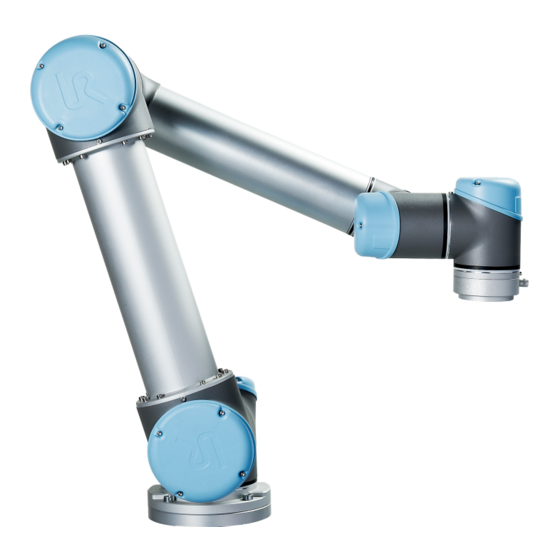
3.1.1 Robot arm configuration Tool mounting Wrist 3 bracket Wrist 1 Wrist 2 Lower arm Elbow Upper arm Base Shoulder Baseplate mounting bracket All rights reserved Service Manual Revision UR5_en_2.0.5... -
Page 11: Brake Release
3.1.2 Brake release If required, the brake on a joint can be released without power connected. IMPORTANT NOTICE: Before releasing a brake it is extremely important to dismount any dangerous tooling for avoiding any hazardous situations. If releasing the brake on Base joint, Shoulder joint or Elbow joint, it is important to make proper mechanical support prior to releasing the brake. -
Page 12: Important - Replacing Cb2 Joints With Cb3 Sparepart Joints
3.1.3 IMPORTANT - Replacing CB2 joints with CB3 sparePart joints PLEASE READ AND UNDERSTAND THE COMPLETE CHAPTER BEFORE REPLACING THE JOINT Universal Robots A/S assumes no responsibility for incorrect use of this procedure. Only special CB3 sparePart parts can be used on CB2. - Page 13 Do not attempt to load sparePart revision firmware on a CB2 joint. This will result in the joint no longer working and need to be re-coded by Universal Robots in Denmark. Only the CB3 sparePart parts listed on previous page can be used All rights reserved Service Manual Revision UR5_en_2.0.5...
- Page 14 3.1.3.2 How to find software version on PolyScope Press the About button on the main Polyscope page and a popup will show the software version. Information on how to update the Polyscope software can be found in the chapter All rights reserved Service Manual Revision UR5_en_2.0.5...
- Page 15 3.3.1.3 How to tell the difference between a CB2 and CB3 sparePart joint It is very important to select the correct revision for each joint but also, if not more important, correct revision for CB2 joints and CB3 sparePart. Below two photos shows the difference. CB2 has green coloured PCB CB3 sparePart has blue coloured PCB All rights reserved...
- Page 16 3.1.3.4 How to select the correct revision for the joint Purpose of this guide: When replacing a CB2 joint with a CB3 sparePart joint, it is necessary to select the correct revision so that it matches the hardware configuration. On the previous pages it’s shown how to find the hardware revision. 1.
- Page 17 Current Joint and press UPDATE Firmware Do not attempt to load sparePart revision firmware on a CB2 joint. This will result in the joint no longer working and need to be re-coded by Universal Robots in Denmark. All rights reserved...
- Page 18 5. A popup will appear where you have to confirm if the selected joint is the one that needs updating. Press OK to continue. 6. A new popup will appear where you have two options: Yes (recommended) - you get a window where you have to select the correct revision No (just upgrade the firmware) –...
- Page 19 7. When Yes (recommended) has been selected a window will show. Here a drop-down, for the joint, can be used to select the correct revision. For CB3 sparePart joints, select the one ending on _sparePart_rev1.conf and select Confirm 8. The process of updating the firmware will now begin. See next steps. All rights reserved Service Manual Revision UR5_en_2.0.5...
- Page 20 9. If a popup appears saying Your configuration is corrupt and could not be loaded your configuration file is not as expected by the software. Please contact your Universal Robots representative. 10. Verify that the firmware has been updated successfully. This can be seen in the status field, then press Back and Return to Normal 11.
- Page 21 3.1.3.5 Connecting a CB3 teach pendant to CB2 masterboard All rights reserved Service Manual Revision UR5_en_2.0.5...
- Page 22 3.1.3.6 Adapters cables There are used 3 different adaptor cables when mounting a CB3 joint onto a CB2 robot arm. Communications cable CB2 to CB3 power cable CB3 to CB2 power cable Communication cable An extension cable is needed on the communication side. This is only an extension and should be used on Size 1 and 4 joints only.
- Page 23 Power cable An adaptor plug is needed for the 48V power. There are two versions. One plug is for CB2->CB3 and one for CB3->CB2. CB2 to CB3 looks like below CB3 to CB2 looks like below Important when replacing a size 1 joint: The connectors need to lay flat, on the connectors’ lowest side, when mounting the blue lid.
-
Page 24: Replacement Of Base Mounting Bracket
3.1.4 Replacement of Base mounting bracket How to replace base mounting bracket Move robot to a comfortable position for replacing the base. If necessary, dismount entire robot arm from work cell and place arm on solid surface. Shut down the controller. ... - Page 25 Slide the grey Teflon ring apart. 10 screws become visible, 5 on each side of joint. Untighten gently the screw with a 7 mm. open-ended spanner about two full rounds, approximately 3 mm. for each screw. Pull the base mounting bracket and Base joint apart and gently twist the two parts in opposite directions around 10 mm.
- Page 26 Replace base mounting bracket and reconnect wires according to illustration – remember to twist the communications wires: Gently insert base plate with screws and washers into the Base joint. Make sure the washers are fully inserted and located on the correct side (this is important) before gently twisting the base mounting bracket and Base joint in opposite directions until a mechanical stop is met.
-
Page 27: Replacement Of Base Joint
3.1.5 Replacement of Base joint How to replace Base joint Move robot to a comfortable position for replacing the joint. If necessary dismount entire robot arm from work cell and place arm on solid surface. Shut down the controller. ... - Page 28 Gently remove black flexible flat ring between Base and Shoulder with a tiny screwdriver or similar tool and twist it around the joint housing. Slide the grey Teflon ring apart. 10 screws become visible, 5 on each side of joint. Untighten gently the screw with a 7 mm.
- Page 29 • Pull away the Base joint from Shoulder joint. Replace Base joint and gently insert Base joint with screws and washers into the Shoulder joint. Make sure the washers are fully inserted and located on the correct side (this is important) before gently twisting the Base joint and Shoulder joint in opposite directions until a mechanical stop is met.
-
Page 30: Replacement Of Shoulder Joint
3.1.6 Replacement of Shoulder joint How to replace Shoulder joint Move robot to a comfortable position for replacing the joint. If necessary dismount entire robot arm from work cell and place arm on solid surface. Shut down the controller. ... - Page 31 Unmount screws around the upper arm as indicated on the illustration: • Pull away the Shoulder joint from upper arm. Replace Shoulder joint and mount screws into shoulder joint. Tighten screws lightly, then tighten in cross order with 3.0Nm. ...
-
Page 32: Replacement Of Elbow Joint
3.1.7 Replacement of Elbow joint How to replace Elbow joint Move robot to a comfortable position for replacing the joint. If necessary dismount entire robot arm from work cell and place arm on solid surface. Shut down the controller. ... - Page 33 Pull Elbow joint and lower arm apart and gently twist the two parts in opposite directions around 10 mm. until a mechanical stop is met (holes are keyhole-type). • Pull away the Elbow joint from lower arm. Disconnect wires between Elbow joint and lower arm 1 x red wire = 48V DC 1 x black wire...
- Page 34 Mount the alignment screw and tighten with 0.4Nm. For separating upper arm from Elbow joint, remove blue lid on Shoulder joint. Disconnect wires between Elbow joint and upper arm 1 x red wire = 48V DC 1 x black wire = GND Green connector = bus cable...
- Page 35 • Pull away the Elbow joint from upper arm. Replace Elbow joint and gently insert lower arm into the Elbow joint. Tighten the 10 screws lightly, then tighten in cross order with respectively 3.0Nm. Reconnect wires between Elbow joint and upper arm as illustrated - remember to twist the communications wires.
-
Page 36: Replacement Of Wrist 1 Joint
3.1.8 Replacement of Wrist 1 joint How to replace Wrist 1 joint Move robot to a comfortable position for replacing the joint. If necessary dismount entire robot arm from work cell and place arm on solid surface. Shut down the controller. ... - Page 37 With a screw driver or similar tool, gently remove nylon ring as illustrated 8 screws become visible, 4 on each side of joint. Untighten gently the screws with a 5.5 mm. open-ended spanner about two full rounds, approximately 3 mm. for each screw. ...
- Page 38 Remove blue lid on Wrist 2 joint. Disconnect wires between Wrist 1 joint and Wrist 2 joint 1 x red wire = 48V DC 1 x black wire = GND Green connector = bus cable Gently remove black flexible flat ring between Wrist 1 and Wrist 2 with a tiny screwdriver or similar tool and twist it around the joint housing.
- Page 39 Slide the grey Teflon ring apart. 8 screws become visible, 4 on each side of joint. Untighten gently the screws with a 5.5 mm. open-ended spanner about two full rounds, approximately 3 mm. for each screw. Pull Wrist 1 joint and Wrist 2 joint apart and gently twist the two parts in opposite directions around 8 mm.
- Page 40 Replace Wrist 1 and gently insert Wrist 1 joint with screws and washers into Wrist 2 joint. Make sure the washers are fully inserted and located on the correct side (this is important) before gently twisting Wrist 1 joint and Wrist 2 joint in opposite directions until a mechanical stop is met. ...
- Page 41 Gently insert Wrist 1 joint with screws and washers into the lower arm. Make sure the washers are fully inserted and located on the correct side (this is important) before gently twisting Wrist 1 joint and lower arm in opposite directions until a mechanical stop is met. ...
-
Page 42: Replacement Of Wrist 2 Joint
3.1.9 Replacement of Wrist 2 joint How to replace Wrist 2 joint Move robot to a comfortable position for replacing the joint. If necessary dismount entire robot arm from work cell and place arm on solid surface. Shut down the controller. ... - Page 43 Gently remove black flexible flat ring between Wrist 1 and Wrist 2 with a tiny screwdriver or similar tool and twist it around the joint housing. Slide the grey Teflon ring apart. 8 screws become visible, 4 on each side of joint. Untighten gently the screws with a 5.5 mm.
- Page 44 • Pull away Wrist 1 joint from Wrist 2 joint. Wrist 1 joint and Wrist 2 joint has now been separated. Perform same procedure for separating Wrist 2 joint and Wrist 3 joint and proceed when done. Replace Wrist 2 and gently insert Wrist 2 joint with screws and washers into Wrist 1 joint. ...
- Page 45 Wrist 1 joint and Wrist 2 joint has now been assembled. Perform same procedure for assembling Wrist 2 joint and Wrist 3 joint. Proceed to chapter 3.1.13 Joint calibration for calibrating the joint. All rights reserved Servicemanual_UR5_en_rev2.0.5...
-
Page 46: Replacement Of Wrist 3 Joint
3.1.10 Replacement of Wrist 3 joint How to replace Wrist 3 joint Move robot to a comfortable position for replacing the joint. If necessary dismount entire robot arm from work cell and place arm on solid surface. Shut down the controller. ... - Page 47 Gently remove black flexible flat ring between Wrist 2 and Wrist 3 with a tiny screwdriver or similar tool and twist it around the joint housing. Slide the grey Teflon ring apart. 8 screws become visible, 5 on each side of joint. Untighten gently the screws with a 5.5 mm.
- Page 48 • Pull away Wrist 2 joint from Wrist 3 joint. Wrist 2 joint and Wrist 3 joint has now been separated. For separating Wrist 3 joint from tool flange, consult chapter 3.1.11 Replacement of tool mounting bracket. Replace Wrist 3 and gently insert Wrist 3 joint with screws and washers into Wrist 2 joint.
- Page 49 Mount blue lid on Wrist 3 joint and tighten with 0.4Nm. Wrist 2 joint and Wrist 3 joint has now been assembled. For assembling Wrist 3 joint and tool flange, consult chapter 3.1.11 Replacement of tool mounting bracket.
-
Page 50: Replacement Of Tool Mounting Bracket
3.1.11 Replacement of tool mounting bracket How to replace tool mounting bracket Move robot to a comfortable position for replacing the tool mounting bracket. If necessary dismount entire robot arm from work cell and place arm on solid surface. ... - Page 51 Slide the grey Teflon ring apart. 8 screws become visible, 5 on each side of joint. Untighten gently the screws with a 5.5 mm. open-ended spanner about two full rounds, approximately 3 mm. for each screw. Pull the tool mounting bracket and Wrist 3 joint apart and gently twist the two parts in opposite directions around 8 mm.
- Page 52 Replace tool mounting bracket and reconnect connectors as illustrated - remember to twist the communications wires Replace tool mounting bracket and reconnect wires correctly. Gently insert tool mounting bracket with screws and washers into the Wrist 3 joint. ...
-
Page 53: Torque Values
3.1.12 Torque values UR5 torque values CONNECTION TORQUE HEAD SIZE Base mounting bracket J0 Base 3.0Nm 7 mm. [J0] Base J[1] Shoulder 3.0Nm 7 mm. [J1] Shoulder Upper arm 3.0Nm Hex key 3 Upper arm [J2] Elbow 3.0Nm Hex key 3... -
Page 54: Joint Calibration
3.1.13 Joint calibration After replacement of joint it is required to calibrate the new joint in order to find the correct zero position of joint. Instruction for calibrating a joint Jog robot to HOME position Illustration shows the HOME position, which is defined as zero position of all joints. ... - Page 55 Enter password lightbot and press OK. lightbot You are now in Expert Mode, press Low Level Control. Select Power On/Off tab and press Turn power on for enabling power to motors. All rights reserved Servicemanual_UR5_en_rev2.0.5...
- Page 56 Select General tab, and select the desired joint by either using the dropdown list or directly press on the joint state line. Press Arm current joint for releasing the brake on the selected joint. Select Move tab and press either Up or Down for the joint to find its index mark. For every time the button is pressed, the velocity of joint will be increased.
- Page 57 Await that state of the joint changes to OK, then press STOP. Index mark has now been found (index mark is not the same position as zero position). Use the Up and Down buttons for navigating the joint to the correct zero position according to the following illustrations.
- Page 58 Zero position illustrations Base: Shoulder, Elbow, Wrist 1: Base zero position is aligned to Shoulder, Elbow and Wrist 1 zero positions are connector in back of robot base. Vertical aligned (if Base if horizontal). Make sure that base of robot is positioned horizontal, use leveler for aligning joints.
- Page 59 Select Calibration tab and press Zero current joint position for calibrating the joint. Press Back for exiting Low Level Control. Back in Expert Mode, press Return to Normal. Verify zero position by moving the robot to HOME. If not satisfied with the zero position, perform the procedure once again.
-
Page 60: Change Joint Id
3.1.14 Change joint ID Each joint has a unique ID no. It is NOT possible to have two joints with the same ID no. on the same robot. Joint Base Shoulder Elbow Wrist 1 Wrist 2 Wrist 3 Example: Wrist 1 (J3) has to be replaced. Spare joint is a Wrist 3 (J5) ... - Page 61 Select Joint ID Select J5 (The one to be changed) Uncheck “Exchange IDs” box In dropdown box, select ID no. 3 Press Set it Confirm Change ID After you have turned power on you can see the joint J5 has changed to J3. All rights reserved Servicemanual_UR5_en_rev2.0.5...
-
Page 62: Joint Spare Part Adaptation Cb2
Base: ID =0 Size 3 Size 4 NB! To use UR5 base as UR5 Elbow it is necessary to change ID and then connect the joints electrically then turn the joint 180 degree in low level control, before mechanical assemble joint. -
Page 63: Controller
3.2 Controller 3.2.1 Handling ESD-sensitive parts To prevent damage to ESD-sensitive parts, follow the instructions below in addition to all the usual precautions, such as turning off power before removing logic cards: Keep the ESD-sensitive part in its original shipping container (a special "ESD bag") until the part is ready to be installed. -
Page 64: Replacement Of Teach Pendant
3.2.2 Replacement of Teach pendant Take care of ESD handling 3.2.1 Handling ESD-sensitive parts How to replace Teach Pendant on Controller Shut down the controller and disconnect the power cable, open the controller cabinet and loosen the 5 Torx screws and remove the alu cover plate. ... - Page 65 Disconnect 4 cables: Red plug with black cable Black USB cable Black DVI cable Black cable for RS232-connection to touchscreen Remove the bracket (foot of the controller box) that holds the cable inlet and pull out the cables and plugs through this hole.
-
Page 66: Replacement Of Masterboard
3.2.3 Replacement of Masterboard Take care of ESD handling 3.2.1 Handling ESD-sensitive parts How to replace Masterboard in Controller box Note: use the same procedure for power down and removing the alu cover plate as in chapter 3.2.2 Replacement of Teach pendant ... -
Page 67: Replacement Of Motherboard
3.2.4 Replacement of Motherboard Take care of ESD handling 3.2.1 Handling ESD-sensitive parts How to replace motherboard in Controller box Note: use the same procedure for power down and removing the alu cover plate as in chapter 3.2.2 Replacement of Teach pendant ... - Page 68 Remove the 4 screws of the 2 holding brackets in the side of the mother board Remove the 4 screws that fix the DVI connector and the RS232 connector. The board can now be removed. There might be some glue on the back side of the mother board that sticks to the aluminum.
-
Page 69: Replacement Of 48V Power Supply
3.2.5 Replacement of 48V power supply Take care of ESD handling 3.2.1 Handling ESD-sensitive parts How to replace 48V power supply in Controller box Note: use the same procedure for power down and removing the alu cover plate and cables for teach pendant as in chapter 3.2.2 Replacement of Teach pendant ... - Page 70 Gently take out the controller module from the Controller box without disconnecting the robot cable and power cable. Power supply is located in the rack under the controller module, the 48V power supply is the lower one in the rack. Before dismounting the 48V power supply, mark and disconnect the cables from that supply.
- Page 71 Remove the screws respectively of the defective 48V power supply from the side of the rack. Replace 48V power supply with new. Reconnect the wires for the 48V power supply. Re-install Controller module in reverse order and connect the 2 wires for the fan and cables for the teach pendant.
-
Page 72: Replacement Of 12V Power Supply
3.2.6 Replacement of 12V power supply Take care of ESD handling 3.2.1 Handling ESD-sensitive parts How to replace 12V power supply in Controller box Note: use the same procedure for power down and removing the alu cover plate and cables for teach pendant as in chapter 3.2.2 Replacement of Teach pendant For replacing the 12V power supply follow exactly the same steps as for the procedure in chapter... -
Page 73: Replacement Of Current Distributor
3.2.7 Replacement of current distributor Take care of ESD handling 3.2.1 Handling ESD-sensitive parts How to replace current distributor in Controller box Note: use the same procedure for power down and removing the alu cover plate and cables for teach pendant as in chapter 3.2.2 Replacement of Teach pendant For replacing the current distributor follow exactly the same steps as for the procedure in chapter... - Page 74 Replace current distributor with new. Reconnect the wires for the current distributor. Re-install Controller module in reverse order and connect the 2 wires for the fan and cables for the teach pendant. Carefully put back the grey alu cover plate, make sure to mount it correct and fix it with the 5 screws.
-
Page 75: Software
If it ain’t broken, don’t fix it: If a robot is operating in an existing application, Universal Robots do not recommend updating software, unless the use of new functions in a newer software release is required for this application. - Page 76 Press button SETUP Robot. In left side menu, select UPDATE Robot. Press button Search for searching after software update on USB-stick. Mark the found software update and press UPDATE. Press YES for updating the software. ...
-
Page 77: Update Joint Firmware
When updating firmware it is strictly forbidden to turn off controller or to remove cable between controller and robot arm during update. Universal Robots can be no means be held responsible for any failed update caused by improper operation. Instruction for updating firmware Prior to updating firmware, it is required to update the robot software. - Page 78 Enter password lightbot and press OK. lightbot You are now in Expert Mode, press Low Level Control. Select the Firmware tab, mark All joints and press UPDATE firmware. Firmware update is being processed, await message that robot firmware updated successfully. It is strictly forbidden to turn off controller during this update.
- Page 79 Back in Expert Mode, press Return to Normal. Firmware has now been updated. All rights reserved Servicemanual_UR5_en_rev2.0.5...
-
Page 80: Using Magic Files
4.3 Using Magic files For easy backup, Universal Robots provides Magic files for automatic copy of data from controller to USB- stick. These files are available: Function: URmagic log file copies the entire log history file to USB-stick ... -
Page 81: Troubleshooting
5. Troubleshooting 5.1 Error codes Note: In some software version, the wording of the error code may be different. Code Error description Issue concerning error How to fix Broken communication error Serial communication Check green 2-wire connectors problem with one or more and wires in joints joints C4A1... - Page 82 problem with joint wire connectors and wires in joints Master sniffed message Serial communication Check green 2-wire connectors addressed to invalid node ID problem with joint and wires in joints In buffer overflow error in Communication error Check connection between Master from PC between Masterboard and masterboard and motherboard,...
- Page 83 detected Check Current Distributor pcb Replace 48V PSU or Curernt Distributor is necessary Robot power up failure Electrical error control box Remove all external connections to I/O-interface of Masterboard Check for short circuit Argument of error code specifies in details what causes the error C50A1 The 24V I/O has voltage, but 24V regulator is off...
- Page 84 3V3 or ADC malfunction C50A28 12V measured too low, 12V, 3V3 or ADC malfunction C50A29 -12V measured too high, Analog I/O malfunction C50A30 -12V measured too low, Analog I/O malfunction C50A31 The other SafetySys will not Euromap67, one or both Check connection to Euromap(if initialize masterboard uP will not...
- Page 85 C55A110 Safety State is changing too often C55A111 On/Off State is changing too often C55A112 Robot current sensors readings differ C55A120 Robot current is too high while emergency stopped C55A121 Robot current is too high while safeguard stopped Overvoltage shutdown Voltage exceeded 55V Check Energy Eaters Replace Energy Eater...
- Page 86 Close to gearbox shear limit Acceleration / deceleration Reduce acceleration in user to high Mechanical problem program in gear related to encoder Replace joint if necessary mounting C71A1 Joint Startup check error Joint hardware is size 1 but Edit config file, contact software is not distributor C71A2...
- Page 87 Distributor pcb e. Fault on the teach pendant C116 Real time part warning Possible CPU-overload due Restructure user program to structure of user program C150 SECURITY CHECK: Position Incorrect TCP and payload Verify TCP and payload settings change too large setting Reduce acceleration in user Too high acceleration,...
-
Page 88: Normal Startup Procedure On A Cb2 Ur5
5.2 Normal startup procedure on a CB2 UR5 1. When you only have the power plug connected and the robot is not turned on the 12 V LED is on.(On the Master board) 2. When you press the power on button on the TP the power up sequence starts 3. -
Page 89: Error Phenomena
5.3 Error phenomena 5.3.1 ControlBox: NO CONTROLLER displayed in Initializing ControlBox = NO CONTROLLER displayed at INITIALIZING screen Replace ethernet cable between motherboard Defective ethernet cable and Masterboard and verify problem is solved Replace Masterboard and verify problem is solved Defective Masterboard Replace motherboard and verify problem is solved Defective motherboard... -
Page 90: No Cable Displayed During Power Up
5.3.2 NO CABLE displayed during power up NO CABLE displayed during power up > controller shuts off after few seconds Measure that 230V AC is present on power input Replace current distributor connector on 12V power supply Measure that 12V DC is present on 12V_IN Replace 12V power supply connector on Masterboard and diode marked 12V in top right corner of Masterboard is lit... -
Page 91: Force Limit Protective Stop
5.3.3 Force limit protective stop Force Limit Protective Stop Payload and tcp settings in Installation\Mounting Adjust payload and tcp must correspond with actual tool. settings Are settings incorrect? Adjust center of mass using Is center of mass very different from tcp point? script code set_payload() (software v1.7 or newer) Are waypoints positioned very close to cylindrical... -
Page 92: Power On Failure In Initializing
5.3.4 Power on failure in Initializing If power turns off a few seconds after Robot Power is turned On in the Initializing window, there are many possible causes for this phenomenon. Most likely it is a control box failure or a communication failure with a joint or the tool. Control box failure Check log history for error messages and consult the section Error Codes for detailed explanation... - Page 93 Communication failure with a joint or the tool connector Check log history for error messages and consult the section Error Codes for detailed explanation Go to LOW LEVEL CONTROL in EXPERT MODE (consult chapter 4.2 for how to access EXPERT MODE) Unmount tool and check Go to tab POWER ON/OFF and press TURN...
- Page 94 Continued Go to tab POWER ON/OFF and press TURN Remove blue lid of joint and POWER ON. Does state of all joints J0-J5 switch check green comm. from BROKEN COMM. ERROR to READY? connector is fully inserted Does state of joint switch to READY? Communication ok to joints and tool Replace joint...
-
Page 95: Checklist After A Collision
5.3.5 Checklist after a collision Checklist after a collision Check log history for error messages and consult the section Error Codes for detailed explanation Stop robot program and eventually press the Emergency button prior to entering the work cell Visually inspect robot arm. Remove lid and inspect Are any parts visually damaged, like damages on parts inside of joint... -
Page 96: Schematic Drawing
5.4 Schematic drawing All rights reserved Servicemanual_UR5_en_rev2.0.5... -
Page 97: Tool Connector
5.4.1 Tool connector Tool connector Pin 1 AI[2] Pin 2 AI[3] Pin 3 DI[0] Pin 4 DI[1] Pin 5 12V/24V DC Pin 6 DO[0] Pin 7 DO[1] Pin 8 Note: Supply current in both modes 12V and 24V is maximum 600 mA All rights reserved Servicemanual_UR5_en_rev2.0.5... -
Page 98: Spare Parts
Controller: 122500 Controller excl. Teach Pendant UR5 122805 Controller incl. Teach Pendant UR5 122092 Teach Pendant incl. Touchscreen and power cables UR5 and UR10 171022 Flash card 106700 Euromap E67 kit (includes E67 module + bypass plug + cable) 123670... -
Page 99: Tool Part List
Spanner Hex 7.0mm UR5 & UR10 109110 Spanner Hex 10.0mm UR10 only Screwdriver Flat 2.5 UR3 & UR5 & UR10 109103 Screwdriver torx T10 UR5 & UR10 109105 Torque wrench Hex 5.5mm Size 1 and Size 2 (1.3 Nm) UR5 & UR10 109106 Torque wrench Hex 7.0mm Size 3 (3.0 Nm) -
Page 100: Packing Of Robot
7. Packing of robot Packing of robot and controller box for shipment Remove any external tooling and external electrical connections. Download the Put_Into_Box program to a USB stick. Download it from: http://www.universal-robots.com/support/ Load program Put_into_box_ur5.urp and follow instructions while removing mounting bolts. While robot folds together, hold a piece of bubble wrap between Shoulder joint and wrists. -
Page 101: Changelog
8. Changelog 8.1 Changelog Date Revision Action Changes 3. sep 2014 UR5_en_2.0 Added Revision 2.0 released 22. feb 2014 UR5_en_2.0.1 Corrected Changelog added Corrected Error code C115: Cause and remedy corrected Corrected Spare part list: new part numbers implemented Added Spare part list: additional part numbers added Corrected New company address added 23.
Need help?
Do you have a question about the UR5 and is the answer not in the manual?
Questions and answers