Universal Robots UR5 with CB2 User Manual
Hide thumbs
Also See for UR5 with CB2:
- Service manual (238 pages) ,
- User manual (223 pages) ,
- Original instructions manual (193 pages)
Table of Contents
Advertisement
Quick Links
Advertisement
Table of Contents

Related Manuals for Universal Robots UR5 with CB2


Summary of Contents for Universal Robots UR5 with CB2
- Page 1 User Manual Version 1.6 Robot: UR5 with CB2...
- Page 2 All Rights Reserved...
-
Page 3: Table Of Contents
Contents 1 Getting started 1.1 Introduction ........1.1.1 The Robot . - Page 4 Contents 3.2 On-screen Editors ....... 37 3.2.1 On-screen Keypad ......37 3.2.2 On-screen Keyboard .
- Page 5 Contents 3.5.3 Setup Screen Language Select ....83 3.5.4 Setup Screen Update ..... . 83 3.5.5 Setup Screen Password .
- Page 6 Contents All Rights Reserved...
-
Page 7: Getting Started
No special knowledge about robots in general or Universal Robots in particular is required. The rest of this chapter is an appetizer for getting started with the robot. -
Page 8: The Robot
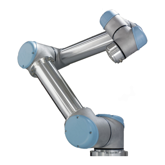
1.1. Introduction 1.1.1 The Robot The robot itself is an arm composed of extruded aluminum tubes and joints. The joints are named A:Base, B:Shoulder, C:Elbow and D,E,F:Wrist 1,2,3. The Base is where the robot is mounted, and at the other end (Wrist 3) the tool of the robot is attached. -
Page 9: Safety Evaluation
1.2. Turning On and Off Features Besides moving through waypoints, the program can send I/O signals to other machines at certain points in the robot’s path, and perform commands like if..then and loop, based on variables and I/O signals. 1.1.3 Safety Evaluation The robot is a machine and as such a safety evaluation is required for each installation of the robot. -
Page 10: Shutting Down The Robot
1.3. Quick start, Step by Step Figure 1.1: The initialization screen 1.2.4 Shutting Down the Robot The power to the robot can be turned off by touching the ’OFF’ button at the initialization screen. Most users do not need to use this feature since the robot is automatically turned off when the controller box is shutting down. - Page 11 1.3. Quick start, Step by Step 8. Wait a minute while the system is starting up, displaying text on the touch screen. 9. When the system is ready, a popup will be shown on the touch screen, stating that the emergency stop button is pressed. 10.
-
Page 12: Mounting Instructions
1.4. Mounting Instructions Front Tilted Figure 1.2: The workspace of the robot. The robot can work in an approxi- mate sphere (Ø170cm) around the base, except for a cylindrical volume directly above and directly below the robot base. 1.4 Mounting Instructions The robot consists essentially of six robot joints and two aluminum tubes, con- necting the robot’s base with the robot’s tool. - Page 13 1.4. Mounting Instructions Surface on which the robot is fitted. It should be flat within 0.05mm Outer diameter of robot mounting flange Cable exit 132 ±0,5 Figure 1.3: Holes for mounting the robot, scale 1:1. Use 4 M8 bolts. All mea- surements are in mm.
- Page 14 1.4. Mounting Instructions Figure 1.4: The tool output flange, ISO 9409-1-50-4-M6. This is where the tool is mounted at the tip of the robot. All measures are in mm. All Rights Reserved...
-
Page 15: Mounting The Controller Box
1.4. Mounting Instructions 1.4.4 Mounting the Controller Box The controller box can be hung on a wall, or it can be placed on the ground. A clearance of 50mm on each side allows for sufficient airflow. 1.4.5 Mounting the Screen The screen can be hung on a wall or on the controller box. - Page 16 1.4. Mounting Instructions All Rights Reserved...
-
Page 17: Electrical Interface
Chapter 2 Electrical Interface 2.1 Introduction The robot is a machine that can be programmed to move a tool around in the robots workspace. Often, it is desired to coordinate robot motion with nearby machines or equipment on the tool. The most straightforward way to achieve this is often by using the electrical interface. -
Page 18: The Safety Interface
2.3. The Safety Interface 2.3 The Safety Interface Inside the control box there is a panel of screw terminals. The leftmost part, in black above, is the safety interface. The safety interface can be used to connect the robot to other machinery or protective equipment, to make sure the robots stops in certain situations. - Page 19 2.3. The Safety Interface The Simplest Emergency Stop Configuration The simplest configuration is to use the internal emergency stop button as the only component to generate an emergency stop. This is done with the configuration shown above. This configuration is the default when the robot leaves the factory, and thereby the robot is ready to operate.
- Page 20 2.3. The Safety Interface All Rights Reserved...
- Page 21 2.3. The Safety Interface An example where multiple UR robots share their emergency stop function is shown below. Connect more robots as robot number 2 is connected. This example uses 24V which works with many other machines. Make sure to comply with all electrical specifications when UR robots share emergency stop with other machinery.
-
Page 22: The Safeguard Interface
2.3. The Safety Interface Note that it is important to make regular checks of the safety stop functionality to ensure that all safety stop devices are functioning correctly. The two emergency stop inputs EA-EB and EEA-EEB are potential free inputs conforming to IEC 60664-1 and EN 60664-1, pollution degree 2, overvoltage cat- egory II. -
Page 23: Automatic Continue After Safeguard Stop
2.3. The Safety Interface How to connect a light guard is shown above. It is also possible to use a category 1 (ISO 13849-1 and EN 954-1) light guard if the risk assessment allows it. When connecting a category 1 light guard use TA and SA and then connect TB and SB with a wire. -
Page 24: Controller I/O
2.4. Controller I/O Parameter Unit 24V Voltage tolerance -15% +20% Current available from 24V supply Overload protection [TA-TB][A ][R ] Voltage 10.5 12.5 [TA-TB][A ][R ] Current [TA-TB][A ][R ] Current protection [SA-SB] Input voltage [SA-SB] Guaranteed OFF if [SA-SB] Guaranteed ON if [SA-SB] Guaranteed OFF if [SA-SB] ON Current (10-30V) [A ][R ] Input voltage... -
Page 25: Digital Outputs
2.4. Controller I/O Electrical specifications of the internal power supply Parameter Unit Internal 24V voltage tolerance -15% +20% Current from internal 24V supply Overload protection External power supply voltage Note that the safeguard (yellow) 24V connections are sourced by the same internal 24V power supply as the 24V connections of the normal I/O, and that the maximum of 1.2 A is for both power sources together. -
Page 26: Digital Inputs
2.4. Controller I/O Load Controlled by Digital Output, External Power If the available current from the internal power supply is not enough, simply use an external power supply, as shown above. 2.4.2 Digital Inputs Parameter Unit Input voltage Input guaranteed OFF if Input guaranteed ON if Guaranteed OFF if ON Current (10-30V) -
Page 27: Analogue Outputs
2.4. Controller I/O Signal Communication with other Machinery or PLCs If communication with other machinery or PLCs is needed they must use pnp technology. Remember to create a common GND connection between the different interfaces. An example where two UR robots (A and B) are communi- cating with each other is illustrated above. -
Page 28: Analogue Inputs
2.4. Controller I/O If the controlled equipment does not take a differential input, an alternative solution can be made as shown above. This solution is not very good in terms of noise, and can easily pick up disturbing signals from other machinery. Care must be taken when the wiring is done, and it must be kept in mind that disturbing signals induced into analog outputs may also be present on other analog I/O. -
Page 29: Tool I/O
2.5. Tool I/O Using Analog Inputs, Differential Current Input When longer cables are used, or if it is a very noisy environment, current based signals are preferred. Also, some equipment comes only with a current output. To use current as inputs, an external resistor is needed as shown above. The value of the resistor would normally be around 200 ohms, and the best result is accomplished when the resistor is close to the screw terminals of the control box. -
Page 30: Digital Outputs
2.5. Tool I/O Color Signal 0V (GND) Gray 0V/12V/24V (POWER) Blue Digital output 8 (DO8) Pink Digital output 9 (DO9) Yellow Digital input 8 (DI8) Green Digital input 9 (DI9) White Analog input 2 (AI2) Brown Analog input 3 (AI3) This connector provides power and control signals for basic grippers and sen- sors, which may be present at on specific robot tool. -
Page 31: Digital Inputs
2.5. Tool I/O Note that the digital outputs in the tool are not current limited and overriding the specified data can cause permanent damage. To illustrate clearly how easy it is to use digital outputs, a simple example is shown. Using Digital Outputs This example illustrates how to turn on a load, when using the internal 12V or 24V power supply. - Page 32 2.5. Tool I/O Parameter Unit Input voltage in voltage mode -0.5 Input voltage in current mode -0.5 Input current in current mode -2.5 Input resistance @ range 0V to 5V kΩ Input resistance @ range 0V to 10V kΩ Input resistance @ range 4mA to 20mA Ω...
-
Page 33: Polyscope Software
Chapter 3 PolyScope Software... -
Page 34: Introduction
3.1. Introduction 3.1 Introduction PolyScope is the graphical user interface (GUI) which lets you operate the robot, run existing robot programs or easily create new ones. PolyScope runs on the touch sensitive screen attached to the control box. To calibrate the touch screen, read section 3.5.6. -
Page 35: Welcome Screen
3.1. Introduction 3.1.1 Welcome Screen After booting up the controller PC, the welcome screen is shown. The screen offers the following options: Run Program: Choose a program to run. This is the simplest way to op- erate the robot, but requires a suitable program to have already been produced. -
Page 36: Initialization Screen
3.1. Introduction 3.1.2 Initialization Screen On this screen you control the initialization of the robot. When turned on, the robot needs to find the positions of each joint. To get the joint positions, the robot needs to move each joint. Status LEDs The status LEDs give an indication of the joints running state. -
Page 37: On-Screen Editors
3.2. On-screen Editors The auto buttons can be pressed individually for each joint, or for the whole robot. Great care should be taken if the robot is touching an obstacle or table, since driving the robot into the obstacle might damage a joint gearbox. Moving directly (Move Buttons) In the case where a joint is in a position where there is a major risk that un- controlled motion would cause damage to the robot or its surroundings, the... -
Page 38: On-Screen Keyboard
3.2. On-screen Editors 3.2.2 On-screen Keyboard Simple text typing and editing facilities. The Shift key can be used to get some additional special characters. 3.2.3 On-screen Expression Editor While the expression itself is edited as text, the expression editor has a num- ber of buttons and functions for inserting the special expression symbols, such as for multiplication and for less than or equal to. -
Page 39: Robot Control
3.3. Robot Control The expression is checked for grammatical errors when the Ok button is pressed. The Cancel button leaves the screen, discarding all changes. An expression can look like this: digital_in[1]=True and analog_in[0]<0.5 3.3 Robot Control 3.3.1 Move Tab On this screen you can always move (jog) the robot directly, either by translat- ing/rotating the robot tool, or by moving robot joints individually. -
Page 40: I/O Tab
3.3. Robot Control Holding down a rotate arrow (button) will change the orientation of the robot tool in the indicated direction. The point of rotation is the TCP , drawn as a small blue ball. Note: Release the button to stop the motion at any time! Move Joints Allows the individual joints to be controlled directly. -
Page 41: Modbus I/O
3.3. Robot Control 3.3.3 Modbus I/O Here, the digital modbus I/O signals as set up in the installation are shown. If the signal connection is lost, the corresponding entry on this screen is disabled. Inputs View the state of digital modbus inputs. Outputs View and toggle the state of digital modbus outputs. -
Page 42: Automove Tab
3.3. Robot Control 3.3.4 AutoMove Tab The AutoMove tab is used when the robot has to move to a specific position in its workspace. Examples are when the robot has to move to the start position of a program before running it, or when moving to a waypoint while modifying a program. -
Page 43: Load/Save
3.3. Robot Control 3.3.5 Installation Load/Save The installation covers aspects of how the robot is placed in its working envi- ronment, both mechanical mounting of the robot, and electrical connections to other equipment. These settings can be set using the various screens under the Installation tab. -
Page 44: Mounting
3.3. Robot Control point that moves in a straight line. It is also the motion of the TCP that is visualized on the graphics tab. The TCP is given relative to the center of the tool output flange, as indicated on the on-screen graphics. The two buttons on the bottom of the screen are relevant when the TCP is changed. -
Page 45: I/O Setup
3.3. Robot Control 3.3.8 Installation I/O Setup Input and output signals can be given names. This can make it easier to remember what the signal does when working with the robot. Select an I/O by clicking on it, and set the name using the on screen keyboard. You can set the name back by setting it to only blank characters. -
Page 46: Modbus I/O Setup
3.3. Robot Control 3.3.9 Installation Default Program The default program will be loaded when the control box is powered up. 3.3.10 Modbus I/O Setup Here, the modbus I/O signals can be set up. Modbus units on specific IP ad- dresses can be added/deleted and input/output signals (registers or digital) on these units can be added/deleted as well. - Page 47 3.3. Robot Control Refresh Push this button to refresh the connectivity status of all modbus signals in the current installation. Add unit Push this button to add a new modbus unit to the robot installation. Delete unit Push this button to delete the modbus unit and all signals added to the unit. Set unit IP Here, the IP address of the modbus unit is shown.
-
Page 48: Features
3.3. Robot Control Set signal address This field shows the address of the signal. Use the on-screen keypad to choose a different address. Valid addresses depends on the manufacturer and config- uration of the modbus unit. It is necessary to have a good understanding of the internal memory map of the Modbus controller in order to make sure the signal address actually corresponds to what is the intention of the signal. - Page 49 - relevant - questions. There are several complicated reasons for this being the case, and in order to address these problems, Universal Robots has developed unique and simple ways for a customer to specify the location of various obejcts relative to the robot.
- Page 50 3.3. Robot Control Delete This button deletes the selected feature and, if any, all sub-features. Show Axes Choose whether the coordinate axes of the selected feature shall be visible on the 3D graphics. The choice applies on this screen and on the Move screen. Joggable Select whether the selected feature shall be joggable.
- Page 51 3.3. Robot Control Add Line Push this button to add a line feature to the installation. A line is defined as an axis between two point features. This axis, directed from the first point towards the second point, will constitute the y-axis of the line coordinate system. The z-axis will be defined by the projection of the z-axis of the first sub point onto the plane perpendicular to the line.
-
Page 52: Log Tab
3.3. Robot Control is directed from the first point towards the second. The positive direction of the z-axis is set so that the angle between the z-axis of the plane and the z-axis of the first point is less than 180 degrees. 3.3.12 Log Tab Robot Health The top half of the screen displays the health of the robot. -
Page 53: Load Screen
3.3. Robot Control Robot Log On the bottom half of the screen log messages are shown. The first column shows the time of arrival of the message. The next column shows the sender of the message. The last column shows the message itself. 3.3.13 Load Screen On this screen you choose which program to load. -
Page 54: Run Tab
3.3. Robot Control In the case that the user double-clicks on a directory, the dialog descends into this folder and presents its contents. File filter By using the file filter, one can limit the files shown to include the type of files that one wishes. -
Page 55: Programming
3.4. Programming This tab provides a very simple way of operating the robot, with as few but- tons and options as possible. This can be useful combined with password pro- tecting the programming part of PolyScope (see section 3.5.5), to make the robot into a tool that can run exclusively pre-written programs. -
Page 56: Program 3.4.2 Program Tab
3.4. Programming 3.4.1 Program New Program A new robot program can start from either a template or from an existing (saved) robot program. A template can provide the overall program structure, so only the details of the program need to be filled in. 3.4.2 Program Tab The program tab shows the current program being edited. -
Page 57: Command Tab,
3.4. Programming Structure tab, described in section 3.4.28. The program name is shown directly above the command list, with a small disk icon that can be clicked to quickly save the program. The lowest part of the screen is the Dashboard. The Dashboard features a set of buttons similar to an old-fashioned tape recorder, from which programs can be started and stopped, single-stepped and restarted. -
Page 58: Command Tab, Move
3.4. Programming 3.4.4 Program Command Tab, Move The Move command controls the robot motion through the underlying way- points. Waypoints have to be under a Move command. The Move command defines the acceleration and the speed at which the robot will move between those waypoints. - Page 59 3.4. Programming size of the blend radius is per default a shared value between all the way- point. A smaller value will make the path turn sharper whereas a higher value will make the path smoother. While the robot is moving through the waypoints with constant speed, the robot cannot wait for either an I/O op- eration or an operator action.
-
Page 60: Program 3.4.6 Setting The Waypoint
3.4. Programming Figure 3.1: Speed profile for a motion. The curve is divided into three seg- ments: acceleration, cruise and deceleration. The level of the cruise phase is given by the speed setting of the motion, while the steepness of the acceleration and deceleration phases is given by the acceleration parameter. - Page 61 3.4. Programming Blend radius If a blend radius is set, the robot trajectory blends around the waypoint, allowing the robot not to stop at the point. Blends cannot overlap, so it is not possible to set a blend radius that overlaps a blend radius for a previous or following waypont.
-
Page 62: Command Tab, Relative Waypoint
3.4. Programming 3.4.7 Program Command Tab, Relative Waypoint A waypoint with the position given relative to the robot’s previous position, such as “two centimeters to the left”. The relative position is defined as the difference between the two given positions (left to right). Note that repeated relative positions can move the robot out of its workspace. -
Page 63: Command Tab, Wait
3.4. Programming var=p[0.5,0.0,0.0,3.14,0.0,0.0]. The first three are x,y,z and the last three are the orientation given as a rotation vector given by the vector rx,ry,rz. The length of the axis is the angle to be rotated in radians, and the vector itself gives the axis about which to rotate. -
Page 64: Command Tab, Action
3.4. Programming 3.4.10 Program Command Tab, Action Sets either digital or analog outputs to a given value. Can also be used to set the payload of the robot, for example the weight that is picked up as a consequence of this action. Adjusting the weight can be neccesary to prevent the robot from security stopping unexpectedly, when the weight at the tool is different to that which is excpected. -
Page 65: Command Tab, Halt
3.4. Programming program. If the “Halt program execution” item is selected, the robot program halts at this popup. 3.4.12 Program Command Tab, Halt The program execution stops at this point. 3.4.13 Program Command Tab, Comment Gives the programmer an option to add a line of text to the program. This line of text does not do anything during program execution. -
Page 66: Command Tab, Folder
3.4. Programming 3.4.14 Program Command Tab, Folder A folder is used to organize and label specific parts of a program, to clean up the program tree, and to make the program easier to read and navigate. A folder does not in itself do anything. 3.4.15 Program Command Tab, Loop Loops the underlying program commands. -
Page 67: Command Tab, Subprogram
3.4. Programming When looping using an expression as end condition, PolyScope provides an option for continuously evaluating that expression, so that the “loop” can be interrupted anytime during its execution, rather that just after each iteration. 3.4.16 Program Command Tab, SubProgram A Sub Program can hold program parts that are needed several places. -
Page 68: Command Tab, Assignment
3.4. Programming 3.4.17 Program Command Tab, Assignment Assigns values to variables. An assignment puts the computed value of the right hand side into the variable on the left hand side. This can be useful in complex programs. 3.4.18 Program Command Tab, If An “if..then..else”... -
Page 69: Command Tab, Script
3.4. Programming The open Check Expression Continuously allow the conditions of the If and ElseIf statements to be evaluated while the contained lines are ex- ecuted. If a expression evaluates to False while inside the body of the If-part, the following ElseIf or Else statement will be reached. 3.4.19 Program Command Tab, Script This command gives access to the underlying real time script language that... -
Page 70: Command Tab, Thread
3.4. Programming An event can be used to monitor an input signal, and perform some action or set a variable when that input signal goes high. For example, in the event that an output signal goes high, the event program can wait for 100ms and then set it back to low again. - Page 71 3.4. Programming The Pattern command can be used to cycle through positions in the robots program. The pattern command corresponds to one position at each execu- tion. A pattern can be given as one of four types. The first three, “Line”, “Square” or “Box”...
-
Page 72: Command Tab, Force
3.4. Programming 3.4.23 Program Command Tab, Force Force mode allows for compliance and forces in selectable axis in the robots workspace. All robot movements under a Force command will be in Force mode. When the robot is moving in force mode, it is possible to select one or more axes in which the robot is compliant. - Page 73 3.4. Programming Simple: Only one axis will be compliant in force mode. The force along this axis is adjustable. The desired force will always be applied along the z-axis of the selected feature. However, for Line features, it is along their y-axis. Frame: The Frame type allows for more advanced usage.
-
Page 74: Command Tab, Pallet
3.4. Programming Test force settings The on/off button, Teach Test, toggles the behavior of the Teach button on the back of the Teach Pendant from normal teaching mode to testing the force command. When the Teach Test button is on and the Teach button on the back of the Teach Pendant is pressed, the robot will perform as if the program had reached this force command, and this way the settings can be verified before actually running the complete program. -
Page 75: Command Tab, Seek
3.4. Programming Pallet Sequence/Anchorable Sequence In an Pallet Sequence node, the motions of the robot are relative to the pallet position. The behavior of a sequence is such that the robot will be at the po- sition specified by the pattern at the Anchor Position/Pattern Point. The remaining positions will all be moved to make this fit. - Page 76 3.4. Programming Stacking When stacking, the robot moves to the starting position, and then moves opposite the direction to search for the next stack position. When found, the robot remembers the position and performs the special sequence. The next time round, the robot starts the search from the remembered position incremented by the item thickness along the direction.
- Page 77 3.4. Programming search from the remembered position, incremented by the item thickness along the direction. Starting position The starting position is where the stack operation starts. If the starting position is omitted, the stack starts at the robots current position. Direction The direction is given by two positions, and is calculated as the position differ- ence from the first positions TCP to the second positions TCP .
-
Page 78: Command Tab, Suppress
3.4. Programming 3.4.26 Program Command Tab, Suppress Suppressed program lines are simply skipped when the program is run. A sup- pressed line can be unsuppressed again at a later time. This is a quick way to make changes to a program without destroying the original contents. All Rights Reserved... -
Page 79: Graphics Tab
3.4. Programming 3.4.27 Program Graphics Tab Graphical representation of the current robot program. The path of the TCP is shown in the 3D view, with motion segments in black, and blend segments (transitions between motion segments) shown in green. The green dots specify the positions of the TCP at each of the waypoints in the program. -
Page 80: Structure Tab
3.4. Programming 3.4.28 Program Structure Tab The program structure tab gives an opportunity for inserting, moving, copy- ing and removing the various types of commands. To insert new commands, perform the following steps: 1) Select an existing program command. 2) Select whether the new command should be inserted above or below the selected command. -
Page 81: Variables Tab
3.4. Programming 3.4.29 Program Variables Tab The Variables tab shows the live values of the variables in the running pro- gram, and keeps a list of variables and values between program runs. The vari- ables tab appears only when it has information to display. The variable names on this screen are shown with at most 50 characters, and the values of the vari- ables are shown with at most 500 characters. -
Page 82: Program 3.4.30 Program 3.5 Setup
3.5. Setup If the ’Prefers to keep value from last run’ checkbox is selected, the vari- able will be initialized to the value found on the Variables tab, described in section 3.4.29. This permits variables to maintain their values between program executions. -
Page 83: Initialize
3.5. Setup 3.5.2 Setup Screen Initialize This screen is used when powering up the robot. Before the robot can op- erate normally, each joint needs to move a little (about 20 ) to finds its exact position. The Auto button drives all joints until they are OK. The joints change drive direction when the button is released and pressed again. -
Page 84: Setup Screen
3.5. Setup Provided the robot is attached to the Internet, new software can be down- loaded. 3.5.5 Setup Screen Password The programming part of the software can be locked using a password. When locked, programs can be loaded and run without the password, but a password is required to create or change programs. -
Page 85: Network
3.5. Setup 3.5.7 Setup Screen Network Panel for setting up the Ethernet network. An Ethernet connection is not neces- sary for the basic robot functions, and is disabled by default. All Rights Reserved... - Page 86 3.5. Setup All Rights Reserved...
-
Page 87: Safety
6. Put a CE mark on the robot installation. In a given robot installation, the integrator is responsible for the compliance with all relevant directives. Universal Robots takes responsibility for the robot itself complying with the relevant EU directives (See section 6.1). -
Page 88: Risk Assessment
4.3 Risk assessment One of the most important things that an integrator needs to do is to make a risk assessment. Universal Robots has identified the potential significant hazards listed below as hazards which must be considered by the integrator. Note that other significant hazards might be present in a specific robot installation. -
Page 89: Emergency Situations
5.10.5. The risk assessment still needs to conclude that the overall robot installation is safe enough of course. A copy of the certification report can be requested from Universal Robots. The standard EN ISO 10218-1:2006 is valid untill the 1st of January 2013. In the mean time the newer version EN ISO 10218-1:2011 and the corrosponding EN ISO 10218-2:2011 addressed to the integrators are also valid. - Page 90 4.4. Emergency situations All Rights Reserved...
-
Page 91: Warranties
Warranty default becoming evident. Ownership of de- vices or components replaced by and returned to Universal Robots shall vest in Universal Robots. Any other claims resulting out of or in connection with the device shall be excluded from this Warranty. Nothing in this Warranty shall at- tempt to limit or exclude a Customer’s Statutory Rights, nor the manufacturer’s... - Page 92 5.2. Disclaimer All Rights Reserved...
-
Page 93: Declaration Of Incorporation
According to the machinery directive 2006/42/EC, the robot is considered a partly completed machine. The following subsections corresponds to and are in accordance with annex II of this directive. 6.2 Product manufacturer Name Universal Robots ApS Address Svendborgvej 102 5260 Odense S Denmark... -
Page 94: Essential Requirements
6.5. Essential Requirements Generic denomination Function General purpose industrial robot Model Serial number of robot arm Serial number of control box Commercial name 6.5 Essential Requirements The individual robot installations have different safety requirements and the in- tegrator is therefore responsible for all hazards which are not covered by the general design of the robot. - Page 95 6.5. Essential Requirements Applied directives 2006/42/EC Machinery Directive 2004/108/EC EMC Directive 2002/95/EC RoHS Directive 2002/96/EC WEEE Directive Applied harmonized standards ISO 13849-1:2006 (Under applied directives) ISO 13849-2:2003 ISO 10218-1:2006 (Partly) ISO 10218-1:2011 (Partly) ISO 10218-2:2011 (Partly) ISO 13850:2006 ISO 12100:2010 ISO 3745:2003 IEC 61000-6-2 ED 2.0:2005 IEC 61000-6-4 AMD1 ED 2.0:2010...
-
Page 96: National Authority Contact Information
Also note that the WEEE directive 2002/96/EC is listed because of the crossed- out wheeled bin symbol on the robot and the control box. Universal Robots reg- isters all robot sales within Denmark to the national WEEE register of Denmark. -
Page 97: Identity And Signature Of The Empowered Person
6.9. Identity and Signature of the Empowered Person 6.9 Identity and Signature of the Empowered Person Name Lasse Kieffer Address Svendborgvej 102 5260 Odense S Denmark Phone number +45 8993 8971 E-mail address kieffer@universal-robots.com Signature All Rights Reserved... - Page 98 6.9. Identity and Signature of the Empowered Person All Rights Reserved...
- Page 99 Appendix A Certifications...
- Page 100 All Rights Reserved...
Need help?
Do you have a question about the UR5 with CB2 and is the answer not in the manual?
Questions and answers