Hach Anatel PAT700 User Manual
Total organic carbon analyzer
Hide thumbs
Also See for Anatel PAT700:
- Operator's manual (158 pages) ,
- User manual (62 pages) ,
- Basic user manual (192 pages)
Table of Contents
Advertisement
Quick Links
Download this manual
See also:
Operator's Manual
Advertisement
Table of Contents
Troubleshooting

Related Manuals for Hach Anatel PAT700


Summary of Contents for Hach Anatel PAT700
- Page 1 FG7005002 ANATEL PAT700 Total Organic Carbon Analyzer User Manual March 2009, Edition 3...
-
Page 3: Table Of Contents
Table of contents Section 1 Before you begin ......................5 1.1 About this manual ........................5 ® 1.2 Anatel PAT700 analyzer overview..................... 6 1.3 RFID technology .......................... 7 1.4 Reading and following instructions ....................7 1.5 Safety............................8 1.6 Hazard information........................8 1.7 FCC conformance........................ - Page 4 Table of contents 4.1 The analysis cycle ........................49 4.2 Accessing run modes .........................50 4.3 Online TOC mode ........................50 4.3.1 Sampling with pressure .....................51 4.3.2 Sampling from a zero pressure system ................51 4.4 Conductivity mode........................51 4.5 Standby mode ..........................52 4.6 Offline mode ..........................52 4.7 Manual TOC Sample........................53 4.8 Self clean mode..........................53 Section 5 Setup...
- Page 5 Table of contents 6.1.2 TOC calibration protocol ....................87 6.1.3 TOC validation protocol ....................87 6.1.4 Conductivity calibration protocol ..................87 6.1.5 System suitability protocol ....................88 6.2 Accessing bottle mode....................... 88 6.3 Bottle mode dialog box ......................88 6.4 Run standards..........................89 6.5 TOC calibration ..........................
- Page 6 Table of contents 10.4 Backdoor password........................144 Section 11 Modbus Protocol ......................145 11.1 Introduction..........................145 11.1.1 Modbus..........................145 11.1.2 Modbus/TCP........................145 11.2 Modbus/TCP driver ........................146 11.2.1 Modbus protocol ......................146 11.2.2 TCP/IP interface ......................147 11.2.3 Data model ........................148 11.3 Data encoding ........................149 11.3.1 Data dictionary.......................152 Section 12 Maintenance and Troubleshooting .................165 12.1 Maintenance...........................165...
-
Page 7: Section 1 Before You Begin
Before you begin 1.1 About this manual Copyright © 2009 by HACH Company, Inc. All rights reserved. No part of the contents of this manual may be reproduced or transmitted in any form or by any means without the written permission of HACH Company. -
Page 8: Anatel ® Pat700 Analyzer Overview
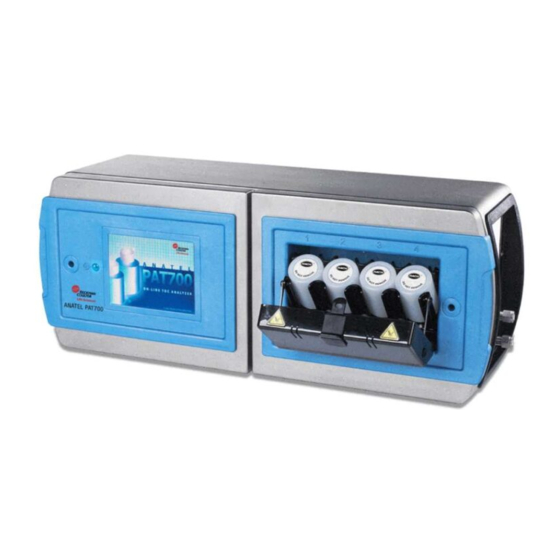
Before you begin ® 1.2 Anatel PAT700 analyzer overview ® The Anatel PAT700 analyzer provides TOC analysis for pure and ultra-pure water processing. The PAT700 oxidizes a water sample to determine the TOC in the sample. The analyzer traps a sample in the analysis cell, exposes the sample to ultraviolet (UV) light, and monitors changes in temperature and conductivity until the sample has completely oxidized. -
Page 9: Rfid Technology
You must comply with all instructions while you are installing, operating, or maintaining the analyzer. Failure to comply with the instructions violates standards of design, manufacture, and intended use of the analyzer. HACH Company disclaims all liability for the customer's failure to comply with the instructions. -
Page 10: Safety
1.5 Safety • Read the Anatel PAT700 TOC Analyzer Manuel de l’opérateur thoroughly before installing or operating the analyzer. Pay attention to all danger and caution statements. Failure to do so could result in serious injury to the operator or damage to the equipment. -
Page 11: Fcc Conformance
• Consult the dealer or authorized service person for help. Any changes or modifications not expressly approved by HACH Company, Inc. could void the user's authority to operate the equipment. 1.8 EU directives The PAT700 Total Organic Carbon Analyzer has been tested and found to be in conformity with the following EU directive: •... -
Page 12: Precautionary Labels
Before you begin 1.9 Precautionary labels Read all labels and tags attached to the analyzer. Personal injury or damage to the instrument could occur if not observed. A symbol, if present on the analyzer, will reference a danger or caution statement in the manual. This symbol, when on the product, references the instruction manual for operation and/or safety information. -
Page 13: Symbols And Marks
Customer satisfaction through continuous quality improvements. 1.11 Patents Apparatus and products are manufactured and sold by HACH Company, Inc. under one or more of the following U.S. patents: 5,260,663 and 5,334,940 and equivalents in other countries where issued. Purchaser is granted a paid-up, non-exclusive license to practice under these patents for the useful life of this apparatus or product. -
Page 14: Customer Service
VGA. Video Graphics Adapter. 1.13 Customer service For customer service: • Voice: US: 1.970.663.9760 or 1.800.373.0531 EU: 41.22.594.6400 • FAX: US: 1.970.663.9761 EU: 41.22.594.6488 • Support hot line: US: 1.877.4 ANATEL (1.877.426.2835) • Website: www.hach.com Page 12... -
Page 15: Section 2 Installation
Section 2 Installation DANGER Tasks involving installation of this equipment have fire, electrical, and pressure related hazards associated with them. These tasks must only be attempted by individuals trained and knowledgeable in the particular task and the associated hazards. 2.1 Installation requirements The quick-connect version of the PAT700 has an IP46 enclosure surrounding the electronics portion of the analyzer. - Page 16 Installation [mm] Dimensions in [597] 23.5 [228.6] [548.6] 21.6 [171.5] [120.6] 6.75 [71.1] [71.1] [203.2] [203.2] [249.9] [90.5] [57.2] 3.56 [118.9] 2.25 4.68 [50.8] 2 [31.8] 1.25 [49.8] [26.1] 1.96 Figure 2 PAT700 mounting dimensions Page 14...
-
Page 17: Mounting General Considerations
Installation [mm] Dimensions in [597] 23.5 [228.6] Figure 3 PAT700 analyzer orientation 2.2.1 Mounting general considerations Follow these guidelines when installing the analyzer: • Locate the analyzer where it is accessible for operation, service and calibration. • Minimize the distance between the water system sample point and the analyzer to allow for representative sampling. -
Page 18: Mounting To A Wall
Use 5/16-inch (8 mm) diameter screws or bolts and nuts to mount the analyzer to a wall or other flat, rigid surface. Use hardware that can withstand the process environment. HACH Company does not supply these screws, bolts, or nuts. •... -
Page 19: Mounting To Dual Instrument Poles
Use four 5/16-inch U-bolts, two for each 2-inch pipe, and eight matching nuts, to mount the analyzer mounting bracket to two rigid instrument poles. Use U-bolts and nuts that can withstand the process environment. HACH Company does not supply U-bolts or nuts. -
Page 20: Plumbing Connections
1/4” (OD) PTFE, FEP, PVDF, or 316 stainless steel tubing. Otherwise, install the factory-supplied 1/4” PFA (perfluoroalkoxy resin) inlet tubing and 1/4” OD polypropylene outlet tubing. HACH Company supplies 5 feet (1.5 meters) of PFA tubing and 10 feet (3 meters) of polypropylene tubing with the analyzer. -
Page 21: Isolation Valve
Installation 2.3.1 Isolation valve To enable manual isolation of the analyzer from input flow, connect the analyzer to the sample supply through a customer-supplied upstream isolation valve. See Figure Process piping Isolation valve (customer-supplied) Water inlet Water outlet Drain Figure 6 PAT700 connection to isolation valve Page 19... -
Page 22: Water Inlet And Outlet
Installation 2.3.2 Water inlet and outlet Tubing connects to the 1/4” inlet (WATER IN) and outlet (WATER OUT) 316 stainless steel compression fittings on the analyzer. See Figure 7. Installation requires a 7/16” wrench. Water inlet Water outlet Figure 7 PAT700 water inlet and outlet connections To connect plumbing to the 1/4”... -
Page 23: Setting Sample Flow Rate
Installation 2.4 Setting sample flow rate The PAT700 is designed to operate with a supply flow rate in the range of 60-300 mL/min. A flow rate in this range ensures a sufficient flow for proper flushing of the analysis cell and protects the analyzers from damage due to excessive flow. -
Page 24: Wiring Connections For Pat700 With Conduit Openings
Installation 2.5 Wiring connections for PAT700 with conduit openings Refer to this section if the PAT700 has three 3/4-inch female NPT conduit openings. • One opening accommodates power supply wiring. • The other two openings accommodate 4-20 mA and/or discrete I/O wiring. •... -
Page 25: Power Supply Wiring
Installation 2.5.1 Power supply wiring WARNING Potential property damage or electrical shock! Adhere to ground network requirements for the facility. Figure 11 illustrates power supply wiring terminals. Table 2 lists specifications for the power supply. Select a wire style and gauge that meets local electrical codes. The power supply wiring connector accepts 10 to 14 AWG wiring. -
Page 26: I/O Wiring
Installation 2.5.2 I/O wiring The analyzer has three 4-20 mA outputs, two discrete inputs, and four discrete outputs. Connect wiring to the connector blocks located on the I/O circuit board. • The connector blocks are a 2-part assembly. • The terminal block connector can be unplugged from the analyzer for easier installation of wiring. - Page 27 Installation Discrete inputs The analyzer has two discrete inputs, referred to as Digital Input 1 and Digital Input 2. Wiring connects to terminals on connector block J24, as listed in Table 4. Both inputs are optically isolated. The inputs are rated for 5 - 30VDC, 2 - 15mA. Terminals 4 and 5 of the discrete input terminal provides a 12 VDC output that can be used to drive each digital input.
- Page 28 Installation The following two wiring diagrams Figure 12 Figure 13 illustrate the digital input wiring: PAT700 Internal Circuit External Control Optional power from control system Input 1 5- 30 Volts DC Control System Input 2 Relay 12VDC + (50 mA Max) Figure 12 Digital input wiring external power - Isolated PAT700 Internal Circuit External Control...
- Page 29 Installation Discrete outputs The analyzer has four discrete outputs. Wiring connects to terminals on connector block J22, as listed in Table • Discrete output 1 is a TOC alarm. The output reports the TOC level as above (low state) or below (high state) the user-specified alarm limit. •...
-
Page 30: Wiring Connections For Pat700 With Quick-Connect Fittings
Installation 2.6 Wiring connections for PAT700 with quick-connect fittings Refer to this section if the PAT700 has five quick-connect fittings, as illustrated in Figure • One connector accommodates power supply wiring. • The other four connectors accommodate 4-20 mA or discrete I/O wiring. •... -
Page 31: Power Supply Wiring
Installation 2.6.1 Power supply wiring WARNING Potential property damage or electrical shock! Adhere to ground network requirements for the facility. WARNING After power supply wiring has been installed, make sure the field wiring box cover is in place and the screw is tightened with a screwdriver to ensure that the cover is properly bonded to protective earth. - Page 32 Installation Discrete inputs The analyzer has two discrete inputs, referred to as Digital Input 1 and Digital Input 2. Wiring connects to terminals as listed in Table 8. Both inputs are optically isolated. The inputs are rated for 5 - 30VDC, 2 - 15mA. Terminals 4 and 5 of the discrete input terminal provides a 12 VDC output that can be used to drive each digital input.
- Page 33 Installation The following two wiring diagrams Figure 15 Figure 16 illustrate the digital input wiring: PAT700 Internal Circuit External Control Optional power from control system Input 1 5- 30 Volts DC Control System Input 2 Relay 12VDC + (50 mA Max) Figure 15 Digital input wiring external power - Isolated PAT700 Internal Circuit External Control...
- Page 34 Installation Discrete outputs The analyzer has four discrete outputs, as listed in Table 9 Table • Discrete output 1 is a TOC alarm. The output reports the TOC level as above (low state) or below (high state) the user-specified alarm limit. •...
-
Page 35: Serial Ports
Installation 2.7 Serial ports The analyzer has the following serial ports: • A female RS-232 serial port for data acquisition and control via a host computer. • A male RS-232 serial port for connection to an external printer (9600 baud, 8 data bits, 1 stop bit, no parity). -
Page 36: Commands
Installation 2.8 RS-232 commands Commands consist of 2-character, ASCII text mnemonics. Some commands require one or more arguments, each delimited by at least one space (ASCII 32, 20 ), following the command mnemonic. Each command string is terminated by a carriage return (ASCII 13, The analyzer responds to commands with an “OK>”... -
Page 37: Mode Setup Commands
Installation 2.8.3 Mode setup commands Command Mode Analyzer activity “MC” Self-clean mode Water flows through cell with UV lamp on. “MD” Automatic TOC mode Continuous TOC analyses. “MO” Manual TOC mode Performs one TOC analysis, then goes to idle mode. “MP”... -
Page 38: Data Logger Commands
Installation Where: Mode State 1 = Online TOC 0 = Idle 2 = Manual TOC 1 = Sampling 3 = Digital TOC 2 = Oxidizing 7 = Online conductivity 4 = Flushing 11 = Offline 12 = StandBy Read-only command enables automatic result printouts from the serial port, such as continuously streaming TOC data after every “SA”... - Page 39 Installation Example: Read command: “LP” or “LP 2007 2007 00” Read format: “LP” or “LP YYYY YYYY MM” Response: “EL” Dump error log Dumps the internal application error log details Example: Read command: “EL” Response: Page 37...
-
Page 40: Parameter Setup Command
Installation 2.8.6 Parameter setup command “SY” Set/get system date and time Example: Read command: “SY” Response: “7 2007 31” Write format: “SY YYYY SS” “SY 2007 25” Disable automatic result printouts “CA” Disables the automatic printout of results for the serial port. for serial port Sets or gets global settings. - Page 41 Installation Example: Read command: “HR” Read format: “HH:mm:SS HH:mm:SS u u u u s u u u u u u u u u u u u HH:mm:SS u u f u u u u u u f” Response: “00:01:00 00:00:00 50 0 1 1 Sensor 0 1 0 3 0 1 0 0 0 0 1 1 00:01:00 25 00 1.000 000 020 005 095 0 0 1.000”...
- Page 42 Installation “PC” Show conductivity calibration history Example: Read command: “PC” Response: “PS” Show system suitability history Example: Read command: “PS” Response: “PT” Show TOC calibration history Example: Read command: “PT” Response: Page 40...
-
Page 43: Diagnostic Commands
Installation “PV” Show TOC validation history Example: Read command: “PV” Response: 2.8.7 Diagnostic commands “RM” Get analyzer mode and state Mode State 0 = Offline 0 = Idle 1 = Online TOC 1 = Start sample 2 = Online conductivity 2= Calibrate 3 = Digital TOC 3 = Start flushing... - Page 44 Installation Page 42...
-
Page 45: Section 3 Startup
3.2 Analyzer initialization With the plumbing, input, outputs and power connections properly established, the ANATEL PAT700 can be initialized and placed into operation. Because the cleanliness of commercially available tubing varies (particularly stainless steel), it is suggested that the analyzer's flow path be thoroughly flushed. This is accomplished by placing the instrument in either on-line TOC mode or self-clean mode for several hours. -
Page 46: Logging On And Off
Startup 3.3 Logging on and off The sign on and sign off icons enable you to sign on or sign off the analyzer. By default, security is disabled and the user cannot sign on. To enable security, see Security, page If you are signed on to the system, touching the sign off icon signs you off and changes the icon to the sign on icon. -
Page 47: Sliding Toolbar
Startup • A display of the current sampling mode. • A process animation. • An OASIS bottle system status indicator in the lower left hand corner. (Touching this icon provides immediate access to the bottle mode dialog box.) • UV lamp status indicators in the lower right hand corner. (Touching this icon provides immediate access to the diagnostics dialog box.) 3.4.1 Sliding toolbar The sliding toolbar consists of icons that enable you to navigate through the analyzer... -
Page 48: Home Screen Data Views
Startup Diagnostics icon allows you to check the health of the analyzer. Touching the icon takes you to the diagnostics dialog box without interrupting the current analysis. Data review icon allows you to view the information from the log file. Touching the icon takes you to the data review dialog box without interrupting the current analysis. - Page 49 Startup uncompensated conductivity. If resistivity is selected, it is displayed as “Resistivity: X.XX MΩ-cm C” for compensated resistivity. The home screen displays conductivity or resistivity, depending on the display units selected in the setup dialog box. • Temperature is the last temperature reading in “Temperature: X.X °C” format or “Temperature: X.X °F”...
-
Page 50: Log View Tab
Startup 3.5.2 Log view tab The log view tab displays all analysis readings or events as they would appear on the printout. The display include all data, up to the last 72 hours, since the last power-up. See Figure Figure 21 Home screen, log view tab 3.5.3 Graph tab The graph tab displays the past three days of data values. -
Page 51: Section 4 Run Modes
Section 4 Run Modes 4.1 The analysis cycle An analysis cycle is comprised of a flush of the analysis cell, oxidation, and idle time (if the cycle time is greater than the combined flush and oxidation time). Oxidation time varies based on the amount of total organic carbon in the sample. Flush time is configurable and idle time varies to allow for varying analysis cycle time. -
Page 52: Accessing Run Modes
Run Modes 4.2 Accessing run modes To access run modes, follow these steps: 1. At the home screen, touch the << icon to open the sliding toolbar. 2. Touch the run mode icon. 3. At the run mode dialog box, touch the radio button that represents the desired run mode. -
Page 53: Sampling With Pressure
Run Modes 4.3.1 Sampling with pressure CAUTION Potential burst hazard! Do not exceed the maximum 100 psi (690k Pa) sample pressure ratings. Note: Using the sample pump on a pressurized system could damage the pump. Do not use the sample pump on a pressurized system. In online TOC mode, the cell valve opens to flush the cell. -
Page 54: Standby Mode
Run Modes 4.5 Standby mode In standby mode, the analyzer verifies that the lamp is off and the valves are open. You can terminate standby mode by switching to another mode. Figure 27 Home screen in standby mode 4.6 Offline mode In offline mode, the analyzer verifies that the lamp is off, the valves are closed, and flow through the analyzer has stopped. -
Page 55: Manual Toc Sample
Run Modes 4.7 Manual TOC Sample A TOC analysis can be performed manually by touching the TOC Manual Sample icon. Upon touching the TOC manual sample icon the analyzer will immediately stop its current operation and run one TOC analysis. Upon completion of the this analysis the analyzer will return to the mode currently selected under the run mode screen. - Page 56 Run Modes In manual self clean mode, the analyzer starts by setting the elapsed time to 0, opening the cell valve to flush the cell, and turning the lamp on. If timed self cleaning was selected, the dialog box displays the time remaining. Otherwise, the dialog box displays the elapsed time.
-
Page 57: Section 5 Setup
Section 5 Setup 5.1 Accessing the setup dialog box 1. At the home screen, touch the << icon to open the sliding toolbar. 2. Touch the setup icon. 5.2 Setup dialog box The setup dialog box allows you to navigate and change analyzer settings. Accessing this dialog box does not interrupt the current operation. -
Page 58: Toc
Setup 5.3 TOC The TOC icon allows you to modify the settings for the TOC operating mode. Any changes are stored in the settings file and become the defaults. 5.3.1 General tab Figure 33 TOC setup dialog box, general tab Flush time text box allows you to specify the amount of time to flush the cell prior to beginning a TOC analysis. -
Page 59: Idle Tab
Setup Average last results checkbox averages the last X TOC analyses. The averaged value is displayed on the home screen and in the log view, logged to the data log, and sent to the printer based on the printer settings. The default value is disabled. Switch lamps when marginal allows you to enable or disable switching of the UV lamps when one lamp reaches a marginal level of UV intensity. -
Page 60: Digital Control Tab
Setup 5.3.3 Digital control tab Figure 35 TOC dialog box, digital control tab Control with digital inputs checkbox allows control of TOC analysis and operation mode through the use of the two digital inputs. The default setting is disabled. If enabled, the analyzer enters the mode defined by input 2 and TOC analysis can be initiated using input 1. -
Page 61: Stabilization Tab
Setup 5.3.4 Stabilization tab Figure 36 TOC dialog box, stabilization tab When the analyzer switches to perform an on-line TOC analysis, after running the analyzer in continuous flow modes such as idle with conductivity, conductivity mode or standby for extend periods of time, a thermal stabilization and cleaning of the analysis cell can reduce the number of TOC analysis cycles necessary to produce stable results. -
Page 62: System
Setup 5.4 System The system icon allows you to modify system settings for the analyzer. 5.4.1 General tab Figure 37 System settings dialog box, general tab Instrument name text box allows you to specify the analyzer name used by the system. You may enter 1 to 13 alphanumeric or symbol characters. -
Page 63: Display Tab
Setup 5.4.2 Display tab Figure 38 System settings dialog box, display tab Set time icon allows you to specify the date and time to be used in the system. You may enter any valid date in “yyyy-mm-dd” format. You may enter any valid time in “hh:mm:ss” or “hh:mm:ss tt”... -
Page 64: Sounds Tab
Setup 5.4.3 Sounds tab Figure 39 System settings dialog box, sounds tab Alarm, warning, stop error, and user feedback list boxes enable you to select the system sounds to be associated with certain alarm types. Test icons play the selected sound for the corresponding alarm. Volume slider controls the level of the volume. -
Page 65: Backlight Tab
Setup DNS server text box sets the DNS server address for the analyzer. You may specify a value of 0 to 255 for each octet. The default value is blank. WINS server text box sets the WINS server address for the analyzer. You may specify a value of 0 to 255 for each octet. -
Page 66: Alarms
Setup 5.5 Alarms The alarms icon allows you to enable or disable TOC and conductivity alarms for the system. Figure 42 Alarm dialog box TOC upper limit text box allows you to set the alarm upper limit for online TOC measurement. - Page 67 Setup The actual (uncompensated) conductivity limits are in accordance with the specifications set forth in the method “<645> Water Conductivity” of the USP 25–NF 20 (January 2002). Table 12 Conductivity alarm limits Uncompensated Temperature Uncompensated Temperature Conductivity (°C) Conductivity (µS/cm) (°C) (µS/cm) The actual sample water temperature is rounded downward to the nearest 5°...
-
Page 68: Analogs
Setup 5.6 Analogs The analogs icon allows you to configure the analog outputs for the system. The analyzer has analog outputs for TOC, conductivity, and temperature. Figure 43 Analog outputs setup dialog box TOC zero scale text box sets the TOC reading that corresponds to the lowest output for the selected range. -
Page 69: Printer
9600 baud, 8 data bits, 1 stop bit, no parity. The printout report requires a 40-column printer. • If the printer is purchased from HACH Company, the switches are preset at the factory. • If a Seiko Instruments DPU-414 Type II thermal printer is installed, the electronic DIP... -
Page 70: Toc Tab
Setup To change the printer settings: 1. Turn the printer power switch OFF. 2. Restore power while pressing the ONLINE button. Release the button when a printout of the current settings begins. 3. Push the ONLINE button again. “DIP SW1” is printed, prompting you for changes to switches 1 through 8. -
Page 71: Conductivity Tab
Setup 5.7.2 Conductivity tab Figure 45 Printer dialog box, conductivity tab Disabled, timed, and percent change radio buttons determine how often an online conductivity reading will be printed in conductivity mode. You may select disabled, timed, or percent change. • Selecting disabled disables printing of online conductivity readings. -
Page 72: Security
Setup 5.8 Security The security icon allows you to modify the security settings for the system. The security dialog box allows configuration of general security features, setting and modifying user accounts, and viewing of the audit trail. 5.8.1 General tab Figure 46 Security settings dialog box, general tab Enable security checkbox allows you to enable or disable the analyzer’s security system. -
Page 73: Settings Tab
Setup Figure 47 Export settings dialog box Filename text box contains the filename for the exported data file, which includes all settings, the data log, and the alarm log. The default file name is mmddyyyyhhmmss (month, day, year, hour, minute, seconds) with the.txt extension. Exporting record no: X bar graph indicator displays the progress of the export. -
Page 74: Users Tab
Setup Remember last X passwords text box allows you to set the number of passwords to keep in memory to prevent a user from using an old password. You may enter a value from 1 to 5 passwords. The default value is 3. Automatically logoff after X minutes text box allows you to set the number of minutes of inactivity before auto logoff. - Page 75 Setup User list box lists most users configured to use this analyzer. Administrator and factory users do not appear in the list. You may add up to 10 additional users to the list. Add icon allows you to add a user to the system. Touching the icon opens the edit user dialog box.
-
Page 76: Audit Trail Tab
Setup Change password checkbox forces the specified user to change his or her password at the next logon. The default setting for this option is disabled. Any time the password entry is modified, this option is enabled. • If a change was made to the password, both passwords in the password and confirm password boxes must match. - Page 77 Setup • Audit trail actions follow the entry header. There are four types of entries possible for this section (data added, data modified, data deleted, or user action). • For the data added type, the keyword “Added” is displayed followed by the item name.
- Page 78 Setup Export icon starts the export. Before the export begins, the analyzer verifies that there is data to export, that you have entered a valid file name, and that a USB flash drive is inserted into the analyzer’s USB port. The file is written to a PAT700 directory in the root directory of the flash drive.
-
Page 79: Bottles
Setup 5.9 Bottles The bottles icon allows you to configure auto acceptance and test completion criteria for bottle mode operations. 5.9.1 TOC calibration tab Figure 54 Bottle test setup dialog box, TOC calibration tab User must manually accept results and auto accept results radio buttons determine whether the outcome of the test are manually or automatically accepted. -
Page 80: Conductivity Calibration Tab
Setup 5.9.2 Conductivity calibration tab Figure 55 Bottle test setup dialog box, conductivity calibration tab User must manually accept results and auto accept results radio buttons determine whether the outcome of the test are manually or automatically accepted. You may select user must manually accept results (default) or auto accept results and return online. -
Page 81: Toc Validation Tab
Setup 5.9.3 TOC validation tab Figure 56 Bottle test setup dialog box, TOC validation tab Return to online mode checkbox enables the analyzer to return to the online mode following the validation. You may enable or disable (default) this option. When enabled, the analyzer returns to online mode following the validation. -
Page 82: Password
Setup 5.10 Password The password icon allows you to change your password. For more information about the user ID and password, see Signing On and Off, page 143. The password icon is highlighted and available when security is enabled. See Security, page Figure 58 Change password dialog box Current password allows you to type your current password. -
Page 83: Factory
Setup 5.11 Factory The factory icon enables factory personnel to enter information that may not be changed by other users. Information on the factory dialog boxes can be viewed by any user but can be changed only by the administrator or a factory user. Entry into the factory dialog box for the purpose of changing the settings requires entry of the user ID and password. -
Page 84: Cell Tab
Setup 5.11.2 Cell tab Figure 60 Factory settings dialog box, cell tab Gain text box (read-only) allows you to view the cell gain factor. Offset text box (read-only) allows you to view the cell offset value. Return icon returns you to the setup dialog box and saves the changes. Any changes are noted in the audit trail. -
Page 85: User Slopes Tab
Setup 5.11.4 User slopes tab Figure 62 Factory settings dialog box, user slopes tab TOC text box (read only) allows you to view the TOC calibration factor. This value is updated after a TOC calibration has been performed. Conductivity text box (read only) allows you to view the conductivity calibration factor. This value is updated after a conductivity calibration has been performed. -
Page 86: Pump Tab
Setup 5.11.6 Pump tab Figure 64 Factory settings dialog box, pump tab The pump tab shows the values used for calibrating the sample pump flow rate and grab sample flush volume, excursion bottle fill time, and bottle back flush time. These are factory-set values that are read-only. -
Page 87: Oxfiles Tab
Setup 5.11.8 OxFiles tab Figure 66 Factory settings dialog box, OxFiles tab The OxFiles tab shows you whether OxFiles buffers are saved or encrypted. These are factory-set values that are read-only. Return icon returns you to the setup dialog box. Page 85... - Page 88 Setup Page 86...
-
Page 89: Section 6 Bottle Mode
Section 6 Bottle Mode 6.1 Calibration and validation Bottle mode allows you to perform calibration, validation, and system suitability test procedures on the PAT700. Proper calibration of the analyzer is critical to maintaining optimum instrument performance. You may perform such functions automatically with the Onboard Automated Standards Introduction System (OASIS™) using the touch-screen interface. -
Page 90: System Suitability Protocol
Bottle Mode 6.1.5 System suitability protocol Perform a system suitability test according to the guidelines established in USP Method <643> using prepackaged 500 ppb sucrose and 500 ppb 1,4-benzoquinone standards. 6.2 Accessing bottle mode To access bottle mode, follow either of these procedures: •... -
Page 91: Run Standards
Bottle Mode 6.4 Run standards The run standards dialog box allows you to select a standards test to run. See Figure Figure 68 Run standards dialog box TOC calibration button takes you to the TOC calibration setup dialog box. Conductivity calibration button takes you to the conductivity calibration load bottles dialog box. -
Page 92: Toc Calibration
Bottle Mode 6.5 TOC calibration TOC calibration ensures the accuracy of the TOC values obtained by the analyzer. TOC values are determined by measuring the change in conductivity of a high-purity water sample as its organic compounds oxidize to carbon dioxide inside the analysis cell. The procedure subtracts the average of a series of background TOC measurements from the average of a series of user-selected standard measurements (in the form of sucrose). -
Page 93: Toc Calibration Procedure
Bottle Mode Figure 70 Custom setup dialog box Bottle selection check boxes enable you to enable or disable the bottles to use in the test. The default setting is all three bottles checked. At least one bottle must be selected. Reps text box allows you to specify the number of repetitions to perform on each bottle. - Page 94 Bottle Mode 5. To use default settings, touch the use default settings radio button in the TOC calibration setup dialog box. To run any other configuration, touch the use custom settings radio button, then define the desired configuration. (See Figure 70, page 91.) The following procedure relies on the recommended default setting.
- Page 95 Bottle Mode Figure 72 Review test setup dialog box • Test setup text lists the bottles that are loaded, test completion actions, acceptance criteria, and, if applicable, schedule. • Bottles icon takes you to the change settings dialog box, where you can change the acceptance limits and completion actions for each test.
- Page 96 Bottle Mode • C of A value text box allows you to enter the certified analysis value for the standard that is being used. • Volume text box allows you to enter the volume of water, in mL, for the specified standards bottle.
- Page 97 Bottle Mode Figure 75 Test running dialog box • After verifying the presence of the appropriate standards, the analyzer performs a temperature stabilization. After the temperature has stabilized, the blank and each standard is analyzed in the proper sequence. • Once all the bottles have been analyzed, the analyzer compares the current results to the factory calibration.
- Page 98 Bottle Mode 11. When the backflush and equalization is completed, the test summary dialog box appears, with the results of the calibration and a notification of whether the calibration failed or passed. The results also appear on the printout if a printer is attached. See Figure Figure 77 Test summary dialog box •...
- Page 99 Bottle Mode Figure 78 Unload/replace bottles dialog box • Unlock icon energizes the bottle bay door lock for five seconds, allowing you to open the door. • Done icon returns you to the bottle mode dialog box. 13. If the test failed or you have rejected the calibration, touch the cancel icon, then touch the checkmark icon to run the calibration again (see Figure 79) or the cancel icon to...
-
Page 100: Conductivity Calibration
Bottle Mode 6.6 Conductivity calibration CAUTION Potential puncture hazard! Contact with the exposed needle could cause serious injury. Use extreme care when installing and removing the sample bottles. Conductivity calibration ensures the accuracy of the conductivity values reported by the PAT700 TOC analyzer. - Page 101 Bottle Mode Figure 80 Load bottles dialog box, conductivity calibration • Bottle positions graphics show you the order in which to install the bottles. • Unlock icon energizes the bottle bay door lock for five seconds, allowing you to open the door. •...
- Page 102 Bottle Mode Verification resistor Figure 81 Verification resistor installed on printer/calibration port Figure 82 Conductivity meter test dialog box • Start test icon reads the value of the resistor. The analyzer then converts this value to conductivity by taking the inverse of the resistance and multiplying it by the cell constant.
- Page 103 Bottle Mode • Cancel icon takes you to a dialog box that notifies you that the test has been cancelled. The next button on the cancellation dialog box takes you to the unload/replace bottles dialog box. All changes made in any of the dialog boxes are lost.
-
Page 104: Toc Validation
Bottle Mode 6.7 TOC validation CAUTION Potential puncture hazard! Contact with the exposed needle could cause serious injury. Use extreme care when installing and removing the sample bottles. The principles and procedures for performing a TOC validation are essentially the same as those used for performing a calibration. - Page 105 Bottle Mode Figure 84 Load bottles dialog box, TOC validation • Bottle positions graphics show you the order in which to install the bottles. • Unlock icon energizes the bottle bay door lock for five seconds, allowing you to open the door. •...
-
Page 106: System Suitability Test
Bottle Mode 6.8 System suitability test CAUTION Potential puncture hazard! Contact with the exposed needle could cause serious injury. Use extreme care when installing and removing the sample bottles. A system suitability test allows you to test analyzer measurements according to the guidelines established in USP Method <643>... - Page 107 Bottle Mode Figure 85 Load bottles dialog box, system suitability test • Bottle positions graphics show you the order in which to install the bottles. • Unlock icon energizes the bottle bay door lock for five seconds, allowing you to open the door.
-
Page 108: Grab Sample
Bottle Mode Where: SR=Suitability response of the analyzer defined as (r – r LR=Limit response of the analyzer defined as (r – r re=Response efficiency of PAT700. =Average TOC response for the blank. =Average TOC response for the sucrose standard. =Average TOC response for the benzoquinone standard. - Page 109 Bottle Mode Figure 86 Load bottles dialog box, grab sample • Bottle positions graphics show you where to install the bottle. • Unlock icon energizes the bottle bay door lock for five seconds, allowing you to open the door. • Back icon takes you to the bottle mode dialog box.
- Page 110 Bottle Mode • Return to online mode after analysis check box allows you to return to the home screen after the test is complete. • Schedule icon takes you to the schedule test dialog box. See Figure 74. All changes made in this dialog box are retained. •...
- Page 111 Bottle Mode Figure 89 Grab sample summary dialog box Export icon opens the export grab sample dialog box. See Figure 90. From there, you can export the grab sample summary to a USB flash drive Run another bottle icon returns you to the load bottles dialog box. Cancel icon takes you to the unload/replace bottles dialog box.
-
Page 112: Excursion Mode
Bottle Mode 6.10 Excursion mode Note: Excursion mode requires the use of an RFID tagged excursion bottle. Excursion mode does not operate without an RFID tagged excursion bottle. Excursion mode enables the analyzer to withdraw a sample from the water system when a predefined TOC level is exceeded or when alarm condition 35 or 36 occurs. -
Page 113: Excursion With Validation
Bottle Mode 6.10.1 Excursion with validation CAUTION Potential puncture hazard! Contact with the exposed needle could cause serious injury. Use extreme care when installing and removing the sample bottles. 1. Install the standards bottles following the instructions as shown in the load bottles dialog box and ensuring that you place the standards bottle in the correct position. - Page 114 Bottle Mode Figure 93 Excursion mode setup dialog box • TOC limit text box allows you to enter a limit an online TOC analysis must reach before an excursion sample is captured. You may specify a value from 1 to 2000 ppb.
-
Page 115: Excursion Without Validation
Bottle Mode 4. When an excursion occurs, an excursion sample captured dialog box opens, and a validation occurs. See Figure • Following the excursion and validation, a validation results dialog box opens that contains the blank and 500 ppb sucrose data. The next arrow on the validation results dialog box takes you to the validation summary dialog box. - Page 116 Bottle Mode Figure 96 Excursion mode without validation dialog box • Bottle positions graphics show you where to install the bottle. • Unlock icon energizes the bottle bay door lock for five seconds, allowing you to open the door. • Back icon takes you to the excursion mode dialog box.
- Page 117 Bottle Mode • TOC limit text box allows you to enter a limit an online TOC analysis must reach before an excursion sample is captured. You may specify a value from 1 to 2000 ppb. The default setting is 500 ppb. •...
- Page 118 Bottle Mode Page 116...
-
Page 119: Section 7 Alarms
Section 7 Alarms 7.1 Alarm indication The analyzer has two basic operational modes: on-line and bottle. On-line TOC and conductivity are the two primary on-line modes (although you can also select standby, off-line, manual, or self clean). In on-line TOC and conductivity modes, the home screen provides an on-screen animation indicating the general state of water flow through the analyzer. -
Page 120: Alarm Acknowledgement
Alarms 7.2 Alarm acknowledgement 1. If an alarm occurs, at the home screen, touch the << icon to open the sliding toolbar. 2. Touch the alarms icon. The alarm acknowledge dialog box allows you to view, acknowledge, or print current or past alarms that are visible in the alarm list. -
Page 121: Alarm Details
Alarms 7.3 Alarm details Touching one of the alarms in the list produces the alarm details dialog box. See Figure 100. Figure 100 Alarm details dialog box Alarm time text label indicates the time of the selected alarm. Alarm severity text label indicates the severity of the type of the selected alarm. Details list box lists a full text description for the selected alarm. -
Page 122: Error Alarms
Alarms 7.4.1 Error alarms Errors occur any time one of the non-critical subsystems fail or a failure occurs from which the analyzer attempts to recover. The animation area flashes red to indicate an error condition is present. When an error condition is present, the analyzer attempts to recover and continue operating. -
Page 123: Critical Error Alarms
Alarms 7.4.2 Critical error alarms A critical error occurs any time the analyzer cannot function due to an error in the system. The error appears as a full-screen, flashing message. All operation ceases until the error condition has been corrected. The current analysis is aborted. Touching the screen provides access to the alarm acknowledge dialog box. - Page 124 Alarms Table 16 Warning alarm messages Code Message Alarm condition • Incorrect bottle detected in position 4. IncorrectBottleLoadedinPosition4 • Analyzer cannot perform bottle test operation. • Not enough fluid in bottle 1 to complete operation. • Check bottle 1 before starting operation. NotEnoughFluidinBottle1 •...
- Page 125 Alarms Table 16 Warning alarm messages Code Message Alarm condition UnableToStartPlumbingTest Analyzer cannot start plumbing test. UnableToPrintDataLog Analyzer cannot print data log. • Analyzer detects that current lamp has failed. LampExtinct • Replace UV lamp. • Bottle installed in location 1 is marked as used. Bottle1MarkedAsUsed •...
-
Page 126: Measurement Alarms
Alarms 7.4.4 Measurement alarms A measurement alarm condition occurs any time the measured TOC exceeds the user-defined limit or conductivity exceeds the USP-defined alarm limit. When an alarm condition occurs, the corresponding data value turns red. If the value drops below the alarm limit, the value returns to its normal color. -
Page 127: Section 8 Diagnostics
Section 8 Diagnostics 8.1 Accessing the diagnostics dialog box • At the home screen, touch the << icon to open the sliding toolbar, then touch the diagnostics icon, or • Touch the dual UV lamp status indicator in the lower right corner of the screen. 8.2 Diagnostics dialog box The diagnostics dialog box provides access to lamp management, system tests, and calibration dates. - Page 128 Diagnostics Lamp test icon turns on each lamp for 180 seconds and tests the UV output level using the UV Detect diagnostics. See Figure 102. If you touch the lamp test icon, the current analysis operation stops, and you are asked if you want to continue. During the test, a message is displayed stating which lamp is being tested and how much time is left in the test.
-
Page 129: Pat700 Lamp Replacement
Diagnostics 8.3.1 PAT700 lamp replacement To replace a lamp, follow these steps: 1. Touch the replace lamp icon. 2. Select the lamp to be replaced. 3. Touch “Run Wizard” to run the lamp replacement wizard. Touch “Replace Now” to skip the replacement wizard. Touch “Print Instructions” to send the lamp replacement instructions to a printer, if connected. -
Page 130: Tests Tab
Diagnostics 8.4 Tests tab The tests dialog box allows you to test the following analyzer functions: RS–232 output, digital I/O, 4-20 mA outputs, printer, plumbing systems, pump, and heat exchanger fan. Figure 104. Figure 104 Diagnostics dialog box, test tab 8.4.1 RS-232 test The RS-232 test icon allows you to test serial communication from the serial port by using the printer port as a return port. -
Page 131: Digital I/O Test
Diagnostics 8.4.2 Digital I/O test The digital I/O test icon allows you to test digital I/O communication. See Figure 106. Before you perform the digital I/O test, make sure I/O wiring is properly connected. 1. Connect the digital inputs to a system that is capable of sending a digital signal 2. -
Page 132: Ma Output Test
Diagnostics 8.4.3 4-20 mA output test The 4-20 mA output test icon allows you to test the 4-20 mA outputs. See Figure 107. To perform the test, you must connect a digital multimeter to the appropriate output to measure the voltage. 1. -
Page 133: Plumbing Test
Diagnostics 8.4.5 Plumbing test The plumbing test icon allows you to test the various analyzer plumbing systems. See Figure 108. You are first notified that the current analysis is stopped and asked if you want to continue. In this dialog box, you may select preconfigured valve and pump combinations to test. - Page 134 Diagnostics Figure 109 Select bottles to load dialog box, plumbing test CAUTION Potential puncture hazard! Contact with the exposed needle could cause serious injury. Use extreme care when installing and removing the sample bottles. CAUTION Potential burst hazard! Do not exceed the maximum 100 psi (690k Pa) sample pressure ratings.
- Page 135 Diagnostics • Unlock icon energizes the bottle bay door lock for five seconds, allowing you to open the door. • Run test icon runs the plumbing test. • Cancel icon returns you to the previous dialog box. All changes made in any of the dialog boxes are lost.
-
Page 136: Pump Test
Diagnostics 8.4.6 Pump test The pump test icon allows you to test pumps. See Figure 112. Before the pump test, you must place a 50 mL graduated cylinder at the analyzer's water outlet. No tubing should be used. A bottle must be installed in position 2 to enable the pump to be primed. - Page 137 Diagnostics Figure 113 Pump calibration dialog box Test time text box indicates the time in seconds that is used for the test and calibration functions. The test time is always 30 seconds. Start test icon opens the pump valve and the grab sample valve, then starts the pump. The pump runs for 30 seconds, then the pump stops.
-
Page 138: Fan Test
Diagnostics 8.4.7 Fan test The fan test icon allows you to test the analyzer’s fans. The analyzer contains an internal online heat exchanger that activates to maintain proper water temperature to the analysis cell. Two fans cool the heat exchanger. Touching the fan test icon opens the fan test dialog box, where you can cycle the fans on and off to ensure their proper operation. -
Page 139: Calibration Dates Tab
Diagnostics Unlock icon energizes the bottle bay door lock for five seconds, allowing you to open the door. Return icon returns you to the diagnostics dialog box. Run icon initiates the RFID test. 8.5 Calibration dates tab Use the calibration dates tab for viewing the last dates that TOC calibration, conductivity calibration, and system suitability test were performed. - Page 140 Diagnostics Page 138...
-
Page 141: Section 9 Data Review
Section 9 Data Review 9.1 Accessing the data review dialog box 1. At the home screen, touch the << icon to open the sliding toolbar. 2. Touch the data review icon. Access to the data review dialog box may be delayed while available data is transferred to the data log. -
Page 142: Export Data
Data Review 9.3 Export data Data are exported in formatted text. The export function sends data to the USB port. Due to driver constraints, the analyzer is not compatible with all USB flash drives. A compatible flash drive is shipped with the analyzer. Figure 118 Export data dialog box Filename text box allows you to specify the filename for the exported data file. -
Page 143: Filter Data
Data Review 9.4 Filter data Data filtering allows you to select the type and range of data to display, export or print. Data can be filtered by test type, date range, or special ranges. Figure 119 Filter data dialog box Data types checkboxes determine what data are displayed in the data review dialog box. - Page 144 Data Review Page 142...
-
Page 145: Section 10 Signing On And Off
Only operator users may be added or deleted from the system. Passwords can be assigned to an operator and administrator. Guest are those without passwords. The factory password is reserved for HACH Company service and support only. • Guest. This user type is any user who does not have a password and can not log on to the system. -
Page 146: Password
Upon successful sign on, the analyzer prompts the user to change the password. Contact HACH Company service at 800.866.7889 to obtain a backdoor password for the analyzer. To obtain the password the factory will request the serial number and current date shown on the analyzer. -
Page 147: Section 11 Modbus Protocol
TOC Analyzers will support reading and writing of these 16-bit registers, which allows the Anatel PAT700 TOC Analyzers to establish a block of data which contains all the process variables, set points, alarms and input/output statuses that are to be made public to a Modbus/TCP client. -
Page 148: Modbus/Tcp Driver
Modbus Protocol 11.2 Modbus/TCP driver 11.2.1 Modbus protocol A typical Modbus/TCP frame consists of the following fields: MBAP Header Function Data The MBAP Header (Modbus Application Protocol Header) consists of 7 bytes of information: It is used for transaction pairing i.e. identification of Transaction Identifier 2 bytes Request/Response transaction. -
Page 149: Tcp/Ip Interface
11.2.2 TCP/IP interface The Modbus/TCP interface is attached to the TCP/IP stack that is implemented within the Anatel PAT700 TOC Analyzer, and will listen to all communications that come in on Modbus/TCP registered port 502. The Modbus/TCP client uses the standard TCP methods for communicating with the driver, as established by the BSD socket interface: connect(), send(), receive() and close(). -
Page 150: Data Model
Since only FC3, FC6 and FC16 are supported in Anatel PAT700 TOC Analyzers, only the Holding Register-type table is required. To access each entry in to the Holding Register table, a starting address (0 indicates the first entry in the table) is required as well as the number of registers that are requested. -
Page 151: Data Encoding
Modbus Protocol 11.3 Data encoding Modbus uses a 'big-endian' representation for addresses and data items. This means that when a numerical quantity larger than a single byte is transmitted, the MOST significant byte is sent first. The following sub-topics describe the different types of encoding and show how the data is encoded as it is within the Modbus/TCP packet. - Page 152 Modbus Protocol Double A Double float value is 64-bits within the Anatel PAT700 TOC Analyzer. FC3 reads 16-bit items at a time; therefore, four registers are required to read each Double float data item. Note: The Modbus/TCP protocol follows Little Endian - byte swap format while transmitting Double float data i.e.
- Page 153 Modbus Protocol Date The Date is transmitted similar to a 32-bit Word with the MOST significant byte first, then the next MOST significant, until all the bytes are transmitted. FC3 reads 16-bit items at a time; therefore, two registers are required to read each Date data item. Combine the two characters in the 1st Register to obtain the four digit year.
-
Page 154: Data Dictionary
Modbus Protocol 11.3.1 Data dictionary The following tables detail the Modbus addresses required to access each item of the public data. Addressing (0 or 1 Based) The addressing within the Modbus/TCP protocol (that is, the data within the physical packet) is 0-based, meaning the first element/item to be accessed is referenced by address 0. - Page 155 Get the instruments serial number. The serial number consists of 10 bytes of printable ASCII characters (0x20-0x7E). Note: Anatel PAT700 currently supports only 4 digit Serial numbers. A register byte value of 0x00 or word value of 0x0000 indicates the end of the Serial Number.
- Page 156 Modbus Protocol Configuration Block The Configuration Data block comprises parameters that directly affect the sampling characteristics of the instrument. Any modifications to these registers will restart the current sample if a sample is active. Note: Use FC16 where '*' is indicated. Configuration Block Size Address...
- Page 157 Modbus Protocol 0170 Total alarm count 0171 Alarm acknowledge 0172 Analog TOC Zero scale R/W* 0176 Analog TOC Full scale R/W* 0180 Analog Temp. Zero scale R/W* 0184 Analog Temp. Full scale R/W* 0188 Analog Cond. Zero scale R/W* 0192 Analog Cond.
- Page 158 Modbus Protocol Address 110 (DHCP Flag) (Format: 16 Bit Word) Get the value that states the instrument's TCP/IP connection type i.e. Either Manual or Auto DHCP. The DHCP Flag consists of 1 word which refers to 0 = Manual and 1 = Auto DHCP.
- Page 159 Modbus Protocol Address 121-122 (Clean Time) (Format: Time 1) Get / Set the instrument's Clean Time. The Clean Time consists of 2 words. Address 123-126 (UTC Date and Time) (Format: Date & Time) Get / Set the instrument's UTC Date and Time. The Date and Time consists of 4 words. Address 127 (UTC Time format) (Format: 16 Bit Word) Get / Set the instrument's Time format.
- Page 160 Modbus Protocol Address 148-151 (Thermistor coefficient A) (Format: Double Float) Get the instrument's Thermistor coefficient A. The Thermistor coefficient A consists of 4 words and read as 64bit double float data. Address 152-155(Thermistor coefficient B) (Format: Double Float) Get / Set the instrument's Thermistor coefficient B. The Thermistor coefficient B consists of 4 words and read as 64bit double float data.
- Page 161 Modbus Protocol Address 169 (Last Alarm) (Format: 16 Bit Word) Get the instrument's last alarm code. The last alarm code consists of 1 word. Refer to Alarm codes, page 119. Address 170 (Total alarm count) (Format: 16 Bit Word) Get the instrument's Total alarm count. The Total alarm count consists of 1 word. Address 171 (Alarm acknowledge) (Format: 16 Bit Word) Set the instrument's Alarm acknowledge flag.
- Page 162 Modbus Protocol Address 222 (UV Lamp 2 State) (Format: 16 Bit Word) Get the instrument's UV Lamp 2 state. The UV Lamp 2 state consists of 1 word which refers to 0 = Good, 1 = Marginal and 2 = Failed. Address 223 (UV Lamp 1 Hours Left) (Format: 16 Bit Word) Get the instrument's UV Lamp 1 Hours Left.
- Page 163 Modbus Protocol Last TOC Analysis Parameters Block The Last TOC Analysis Parameters block comprises of parameters that are updated immediately after a successful TOC Analysis. Last TOC Analysis Parameters Block Size Address Register Description Access (Words) 0300 Final TOC 0304 Temperature 0308 Compensated Conductivity...
- Page 164 Modbus Protocol User Security Block The User Security block comprises of parameters that are essential to Logon or change security features in PAT700. Note: Use FC16 where '*' is indicated. User Security Block Size Address Register Description Access (Words) 0400 User ID 0415 Password...
- Page 165 Modbus Protocol Error Codes The following are the error codes used in PAT700 Modbus/TCP protocol. Exception Code Explanation 0x01 Illegal Function 0x02 Illegal Data address 0x03 Illegal Data value 0x04 Device Failure 0x08 Access Denied Page 163...
- Page 166 Modbus Protocol Page 164...
-
Page 167: Section 12 Maintenance And Troubleshooting
UV lamps have a limited life and should be replaced every six months. The measurement cell should have a yearly calibration verification. Maintenance procedures may be performed either by the user or by HACH Company customer service personnel. The most common maintenance procedure is UV lamp replacement. -
Page 168: Lamp Replacement Procedure
Maintenance and Troubleshooting 12.1.2 Lamp replacement procedure Replacement UV lamp part number: FG7001014. To replace a lamp, follow these steps: 1. At the home screen, touch the << icon to open the sliding toolbar. 2. Touch the diagnostics icon or touch the dual UV lamp status indicator in the lower right corner of the screen. - Page 169 Maintenance and Troubleshooting WARNING Chemical Hazard! The UV lamps contain mercury and mercury vapor. Handle lamps with care to avoid exposure. Cleanup of mercury should be in accordance with local, state, and federal guidelines. The mercury-containing UV lamps within this equipment must be disposed of accordance with local, state and federal law. Note: Leaving fingerprints on the lamp’s glass surface can diminish UV output, resulting in measurement error.
- Page 170 Maintenance and Troubleshooting 8. Grasp the lamp module on the right and left side and squeeze the module locking clips to release the module from the manifold assembly. Pull straight upward until the lamps clear the manifold. 9. Press and hold the lamp retaining clip to release the UV lamp. While pressing the lamp retaining clip, carefully withdraw the lamp from the lamp holder.
- Page 171 Maintenance and Troubleshooting 10. Holding the lamp by its metal sleeve, insert the new lamp into the lamp holder hole and clip into place. The lamp is self-aligning. Ensure that the lamp is locked in place by the lamp retaining clip. 11.
-
Page 172: Self Clean Mode
Maintenance and Troubleshooting 12. Reconnect the lamp power connectors by carefully reinserting the connectors and locking them in place by twisting the locking rings clockwise. 13. Close and lock the door. 14. Restore power to the analyzer. When the analyzer is powered on after the lamp replacement procedure, the analyzer performs a lamp test to make sure the replaced lamp is working. -
Page 173: Water Filter Replacement
Maintenance and Troubleshooting 12.2 Water filter replacement CAUTION Burn and pressure hazard! Water is pressurized and may be hot (up to 95 °C [203 °F]). Protective eye wear is required while performing this task, and the sample line must first be depressurized before the water filter is disconnected. The analyzer has an internal water filter, which can be replaced (replacement filter part number FG7001015). -
Page 174: Troubleshooting
Maintenance and Troubleshooting 12.3 Troubleshooting The PAT700 incorporates extended diagnostic and reporting facility to inform the user about the nature of a problem. Alarm codes, with user-initiated diagnostic tests, serve to isolate the source of the problem.The PAT700 constantly monitors its operation and measurement values for alarm conditions. -
Page 175: Technical Support
Technical support engineers can provide high quality advice and recommendations for applications, product operation, measurement specifications, hardware and software, factory and customer site training. Any questionable problems should be referred to HACH Company and the following information should be included in any correspondence with the factory: •... -
Page 176: Return Procedures
Maintenance and Troubleshooting 12.3.3 Return procedures To return the Anatel PAT700 TOC Analyzer for service, first obtain a return material authorization number (RA#). The RA# is necessary for any analyzer that requires repair or calibration by an authorized service center. Include the RA# on the shipping label when the analyzer is returned. - Page 177 Maintenance and Troubleshooting To avoid damaging the analyzer: • Do not leave water inside the analyzer before putting it into storage. • Do not expose the analyzer to temperature extremes. To purge the PAT700 of entrained water: 1. Remove the analyzer from service and disconnect it from the water system. 2.
- Page 178 Maintenance and Troubleshooting Page 176...
-
Page 179: Section 13 Specifications
Section 13 Specifications PAT700 specifications are subject to change without notice. TOC specifications Operating range 0.5 to 2,000 ppb as carbon 0.2 µS/cm for all waters, 1.0 µS/cm for all neutral waters, 5 µS/cm for water with Conductivity Range for TOC as the sole conductive species. -
Page 180: Specifications
Specifications Input/output specifications Analog output specifications Analog outputs Three, opto-isolated Variables TOC, conductivity, and temperature Range Configurable over 4-20 mA Alarm level Configurable: 2, 22, or last value Discrete input specifications Discrete inputs Two, opto-isolated Input one TOC analysis start Input two TOC/Flow with conductivity mode change Discrete output specifications... -
Page 181: Section 14 Ce Conformance
Section 14 CE Conformance Page 179... - Page 182 CE Conformance Page 180...
-
Page 183: Section 15 Theory Of Operation
Section 15 Theory of Operation The Anatel PAT700 on-line TOC analyzer provides TOC analysis for pure and ultra-pure water processing. The PAT700 oxidizes a water sample to determine the TOC in the sample. The analyzer traps a sample in the analysis cell, exposes the sample to ultraviolet (UV) light to oxidize a sample of water (photolysis), and monitors changes in temperature and conductivity until the sample has completely oxidized. - Page 184 Theory of Operation An RFID system is comprised of a "tag" and a "reader/writer". In the PAT700 analyzer, the tag is attached to the standards bottles used in calibrations (conductivity and TOC), validations, system suitability tests, and excursion mode. The RFID tag consists of a microchip attached to a radio antenna mounted on a substrate.
-
Page 185: Section 16 Pat700 Default Settings
Section 16 PAT700 Default Settings Table 17 Default settings TOC Setup Default Setting Flush time 1 minute Cycle time Use pump Disabled Bypass during analysis Disabled Average last results Disabled Flow during idle With conductivity Control with digital inputs Disabled Stabilization - Time between analysis 2 hours Stabilization - Time... - Page 186 PAT700 Default Settings Security Settings Default Setting Enable security Disabled Enable data logging Enabled Password expires in # days Remember last # passwords Automatically log off after # minutes Administrator user name Administrator Administrator ID Admin Administrator password 123456 User's full name Blank User ID Blank...
Need help?
Do you have a question about the Anatel PAT700 and is the answer not in the manual?
Questions and answers