Sony IPELA PCS-XG100 Operating Instructions Manual
Hd visual
communication
system
Hide thumbs
Also See for IPELA PCS-XG100:
- Manual (86 pages) ,
- System integration manual (21 pages) ,
- Installation manual (2 pages)
Table of Contents

Related Manuals for Sony IPELA PCS-XG100


Summary of Contents for Sony IPELA PCS-XG100
- Page 1 4-455-810-19 (1) HD Visual Communication System Operating Instructions (Version 1.4) Before operating the unit, please read this manual thoroughly and retain it for future reference. PCS-XG100/XG77 PCS-XG100S/XG77S © 2013 Sony Corporation...
- Page 2 Refer To reduce the risk of fire, use only No. 26 to these numbers whenever you call upon AWG or larger telecommunication line your Sony dealer regarding this product. cord. Model No. ______________ When installing the installation space must Serial No.
- Page 3 Manufacture Type No. FCC radio frequency (RF) Exposure Sony VGP-AC19V45 Guidelines in Supplement C to OET65. This Any other power sources may result in equipment has very low levels of RF energy hazards such as a fire.
- Page 4 Sony service to conduct a videoconference, but it also facility. covers non-ISDN lines. If you use ISDN lines, consult your Sony dealer for more For the customers in Europe information. The manufacturer of this product is Sony •...
- Page 5 Halutessasi lisätietoja, käy osoitteessa: http://www.compliance.sony.de/ Par la présente Sony Corporation déclare que l’appareil PCS-XG100/XG77/ XG100S/XG77S/ HD Visual Communication System est conforme aux exigences essentielles et aux autres dispositions pertinentes de la directive French 1999/5/CE.
- Page 6 Hungarian előírásainak. További információkat a következő weboldalon találhat: http://www.compliance.sony.de Con la presente Sony Corporation dichiara che questo PCS-XG100/XG77/ XG100S/XG77S/ HD Visual Communication System è conforme ai requisiti Italian essenziali ed alle altre disposizioni pertinenti stabilite dalla direttiva 1999/5/CE. Per ulteriori dettagli, si prega di consultare il seguente URL: http://www.compliance.sony.de/...
- Page 7 1999/5/ES. Za podrobnosti vas naprošamo, če pogledate na URL: http://www.compliance.sony.de/ Por medio de la presente Sony Corporation declara que el PCS-XG100/XG77/ XG100S/XG77S/ HD Visual Communication System cumple con los requisitos esenciales y cualesquiera otras disposiciones aplicables o exigibles de la Spanish Directiva 1999/5/CE.
- Page 8 1999/5/EY oleellisten vaatimusten ja sitä Finnish koskevien direktiivin muiden ehtojen mukainen. Halutessasi lisätietoja, käy osoitteessa: http://www.compliance.sony.de/ Par la présente Sony Corporation déclare que l’appareil PCS-RFZ1/RF Remote Commander est conforme aux exigences essentielles et aux autres dispositions French pertinentes de la directive 1999/5/CE.
- Page 9 1999/5/ES. Za podrobnosti vas naprošamo, če pogledate na URL: http://www.compliance.sony.de/ Por medio de la presente Sony Corporation declara que el PCS-RFZ1/RF Remote Commander cumple con los requisitos esenciales y cualesquiera otras disposiciones aplicables o exigibles de la Directiva 1999/5/CE. Spanish Para mayor información, por favor consulte el siguiente URL:...
- Page 10 SONY LIMITED WARRANTY - Please visit http://www.sony.com/psa/warranty for important information and complete Operating or storage location terms and conditions of Sony’s limited Avoid operating or storing the system in the warranty applicable to this product. following locations: • Extremely hot or cold places For the customers in Canada •...
-
Page 11: Table Of Contents
Table of Contents Chapter 1: Installation and Preparation Using This Manual ....................18 Features ........................19 System Components ....................22 Basic System Components ................22 Optional Equipment ..................25 System Configuration ..................... 27 System Configuration via a LAN ..............27 System Configuration via an ISDN .............. - Page 12 Chapter 2: Registration and Setup for System Administrators Registering Local Information .................62 Opening the Setup Menu ..................62 Line Interface Setup Menu .................66 Dial Setup Menu ....................66 Answer Setup Menu ...................67 Multipoint Setup Menu ..................67 Communication Setup Menu ................68 Audio Setup Menu .....................72 Video Setup Menu ....................75 LAN Setup Menu ....................78 QoS Setup Menu ....................82...
- Page 13 SIP (UC) Connections ..................113 About the Network Routing Check ............... 115 Chapter 3: Basic Connection Starting a Connection by Calling a Remote Party ..........116 Turning On the Power ..................116 Calling a Remote Party by Using the Connect Menu ........117 Calling a Remote Party by Entering Their Address or Number Directly (Direct Dial) ..................
- Page 14 Switching Video and Audio at the Same Time ..........153 Switching the Picture from the Remote System ..........154 Switching the Picture Displayed on the Monitor Screen ........155 Capturing the Screen ....................157 Chapter 4: Connection with Optional Equipment Using a Tools Menu ....................159 Using the Computer Picture for Presentation ............162 Connecting a Computer ..................162 Making a Presentation ..................162...
- Page 15 Adding Optional Software ..................196 Confirming that the Installation of the Optional Software is Complete ..197 Configuring Multipoint ..................198 Setting Up Multipoint ..................198 Registering the Remote Parties in the Multipoint Connection List ....198 Starting a Multipoint Connection ................202 Calling Remote Parties ..................
- Page 16 Installing the Camera Using the M3 Fixing Screw Holes ........235 Using the Supplied Hook-and-Loop Pads ............236 HD Camera Unit Parts Identification ..............236 SRG-120DH .....................236 PCSA-CXG100 ....................238 EVI-H100V ......................239 EVI-HD7V/HD3V ...................242 Pan/Tilt Range ....................245 Phenomena Specific to CMOS Image Sensors ............246 Appendix Location and Function of Parts and Controls ............247 PCS-XG100S/XG77S HD Visual Communication System ......247...
- Page 17 Glossary ........................ 274 Menu Configuration ....................277 Index ........................291 “IPELA” and are trademarks of Sony Corporation.
-
Page 18: Chapter 1: Installation And Preparation
audio data, and encrypted data from a Chapter 1: computer. Chapter 6: Multipoint Connection Installation and This chapter shows you how to connect your system to multiple sites. Multipoint Preparation connection requires installation of the optional PCSA-MCG106/MCG109 HD MCU software in your Visual Communication System. -
Page 19: Features
reception. The built-in echo canceller Features supports up to 16 kHz. Supports data communication The PCS-XG100/XG77/XG100S/XG77S Image output from a computer can be HD Visual Communication System is a transmitted simultaneously with camera communication system that provides face- images. to-face communications with a remote party by transmitting and receiving images and High transmission speeds and sound via LAN (Local Area Network) or... -
Page 20: On-Screen Keyboard
Note of the System. You can easily switch the For details on supported USB storage devices, shooting area only by recalling the preset consult your Sony dealer. position. HD recording RF (Radio Frequency) Remote Video and audio can be recorded to a USB... - Page 21 Supports encrypted connection The system allows you to make a strictly confidential connection using standard encryption, which complies with the H.233, H.234 and H.235 standardized by the ITU-T. Supports multipoint connection Installing the optional PCSA-MCG106/ MCG109 HD MCU software in your Visual Communication System allows connection among multiple points via a LAN or/and ISDN line.
-
Page 22: System Components
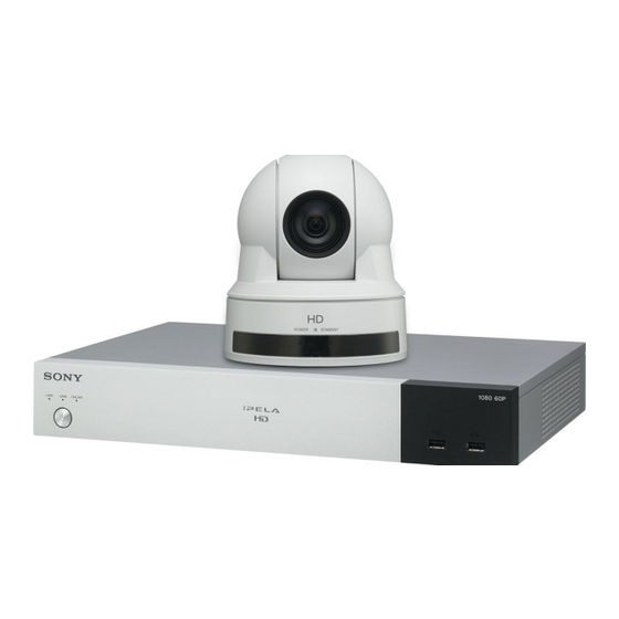
System Components The PCS-XG100/XG77/XG100S/XG77S HD Visual Communication System is composed of basic system components for a basic communication, and optional equipment for an enhanced communication. Basic System Components Note This manual explains how to operate the following systems. • PCS-XG100 HD Visual Communication System package that includes the main unit, one SRG-120DH HD Camera Unit, and two PCS-A1 Microphone units. - Page 23 Unit Description SRG-120DH Full HD rotating camera with a wide-angle lens (71- HD Camera Unit degree wide angle of view) that is ideal for use as a remote camera for videoconferences in medium- sized rooms. PCS-A1 Microphone Omni-directional microphone that picks up sound relatively from all directions, allowing participants to speak from any location.
- Page 24 Components packaged in the PCS-XG100S Unit Description PCS-XG100S HD Visual Contains the video codec, audio codec, echo Communication System canceller, network interfaces and system controller. PCS-RFZ1 Use this to control the HD Visual Communication Remote Commander System after pairing it with the system. VGP-AC19V45 AC adaptor Supplies power to the Communication System.
-
Page 25: Optional Equipment
Unit Description VGP-AC19V45 AC adaptor Supplies power to the Communication System. PCS-A1 Microphone Omni-directional microphone that picks up sound relatively from all directions, allowing participants to speak from any location. It is recommended to use in a quiet situation (one piece supplied). Optional Equipment Optional equipment especially designed for use with the Communication System... - Page 26 Unit Description Mobile Access Software Use this to connect the PCS-XG100/XG77/XG100S/ PCSA-SAG8 (for XG77S to a mobile terminal. PCS-XG100/XG100S) PCSA-SAG1 (for PCS-XG77/ XG77S) System Components...
-
Page 27: System Configuration
System Configuration The PCS-XG100/XG77/XG100S/XG77S HD Visual Communication System has various system configuration capabilities using the basic components and optional equipment. This section describes the capabilities and necessary equipment for some typical configuration examples. Notes • The SRG-120DH HD Camera Unit supplied with the PCS-XG100/XG77 is depicted as the camera unit in the system configuration examples. -
Page 28: System Configuration Via An Isdn
System Configuration via an ISDN Connection to ISDN is required to use the PCSA-B384S or PCSA-B768S ISDN Unit especially designed for use with this system. Note ISDN is supported in version 1.41 and later. This allows you to: • Have a point-to-point HD visual communication over ISDN. •... -
Page 29: System Configuration Via A Sip / Sip (Uc)
System Configuration via a SIP / SIP (UC) This allows you to: • Have an HD visual communication with an IP telephone, etc. using SIP. • Have a visual communication using an SIP (UC) connection. • Pick up sound in stereo by using two microphones connected to the system. System configuration 1 PCS-XG100S/XG77S HD Visual Communication System... -
Page 30: System Configuration Using Two Lan Connections
System Configuration Using Two LAN Connections (PCS-XG100/ XG100S only) This allows you to: Connect your system to two networks using the 1 (LAN1) and 2 (LAN2) connectors. You can use the 1 connector to connect to a private network in your company and 2 connector to connect to the internet or locations outside of your company. -
Page 31: System Configuration Via A Lan For Multipoint
PCS-XG77/XG77S. • A license key must be purchased and installed to use the HD MCU software. For details on purchasing license keys, consult your Sony dealer. For details on installing license keys, see “Adding Optional Software” on page 196. -
Page 32: System Configuration Via A Lan And Isdn For Multipoint
PCS-XG77/XG77S. • A license key must be purchased and installed to use the HD MCU software. For details on purchasing license keys, consult your Sony dealer. For details on installing license keys, see “Adding Optional Software” on page 196. - Page 33 System configuration ISDN ISDN This diagram depicts a system configuration using the PCSA- B768S ISDN Unit. 1 PCS-XG100S HD Visual Communication System 2 SRG-120DH HD Camera Unit (supplied with the PCS-XG100/XG77) 3 PCS-RFZ1 Remote Commander 4 TV monitor (not supplied) 5 PCS-A1 Microphones 6 PCSA-MCG106/MCG109 HD MCU software (not supplied) 7 PCSA-B384S (not supplied) or PCSA-B768S (not supplied) ISDN Unit...
-
Page 34: System Connections
Be sure not to turn off the Communication System or disconnect the cable during upgrading. Otherwise, it may cause a malfunction of the system. • We recommend using Sony’s HDMI cable. System Connections... -
Page 35: System Connection Via A Lan
System Connection via a LAN SRG-120DH HD Camera Unit to HDMI, PCS-A1 microphone VISCA IN, DC 12V Camera cable to CAMERA to MIC (A1) PCS-XG100S/XG77S Visual Communication System to DC19.5V HDMI-1 Power cord HDMI cable to a wall outlet AC adaptor to HDMI IN UTP cable (category 6, straight) to LAN... -
Page 36: System Connection Via An Isdn
System Connection via an ISDN Note ISDN is supported in version 1.41 and later. SRG-120DH HD Camera Unit PCS-A1 Microphone Interface ISDN Unit cable to TERMINAL (supplied with ISDN Unit) to HDMI, PCSA-B384S ISDN Unit VISCA IN, Camera DC 12V cable to ISDN 1-3 PCSA-B768S... -
Page 37: System Connection Via A Sip
System Connection via a SIP SRG-120DH HD Camera Unit PCS-A1 microphone to HDMI, VISCA IN, Camera DC 12V cable AC adaptor Power cord to CAMERA to MIC (A1) to a wall outlet to DC19.5V SIP server PCS-XG100S/XG77S HD Visual HDMI-1 Communication System HDMI cable to LAN... -
Page 38: Attaching The Camera Unit To A Tripod
• The REC OUT jack is used to make an audio recording of a communication. This is not used during regular communication. Attaching the Camera Unit to a Tripod To attach the Camera Unit to a tripod Attach the tripod to the tripod attachment screw hole at the bottom of the camera unit. -
Page 39: Preparing The System
Preparing the System Inserting Batteries into the Remote Commander CAUTION Danger of explosion if battery is incorrectly replaced. Replace only with the same or equivalent type recommended by the manufacturer. When you dispose of the battery, you must obey the law in the relative area or country. Most of the operations with the HD Visual Communication System can be controlled with the supplied Remote Commander. -
Page 40: Pairing The Remote Commander With The Main Unit
• Make sure to insert the batteries with the polarities in the correct direction. • Do not mix old and new batteries, or different types of batteries. • Do not attempt to charge the batteries. • If you do not intend to use the Remote Commander for a long period of time, remove the batteries. - Page 41 Within 5 minutes of the Home menu appearing, bring the Remote Commander as close to the Communication System as possible, press the TOOLS and RETURN buttons at the same time, and hold the buttons for at least 3 seconds. The LED indicator flashes rapidly. Press the ENTER button on the Remote Commander.
-
Page 42: Turning The System On/Off
Turning the System On/Off This section describes how to turn on or off the Communication System. Turning On Turn on the TV monitor. Turn on the power of any other equipment to be used for this connection. Press the (power) switch on the Communication System to turn it on. (power) switch (power) switch indicator on the Communication System flashes. -
Page 43: Standby Mode Function
If connection of the Camera Unit, ISDN Unit, etc. to the Communication System is not re-established even after the system power is recovered, consult a Sony dealer. • You can check the versions of the Communication System, optional dedicated equipment connected and the application software installed using the Machine Status menu. -
Page 44: Turning Off
To release the standby mode Press any button on the Remote Commander. To specify the standby time Specify the time that you want the system to remain on before entering into standby mode (1 to 99 minutes) by setting “Standby Time” of the Device Setup page of the General setup menu. - Page 45 Press the VOLUME +/– buttons on the Remote Commander to set the volume level on the adjustment bar displayed on the screen to the middle position. Adjust the volume on the TV monitor so that you can properly hear a remote party’s speaking.
-
Page 46: Setting Up The System Immediately After The Installation - Initial Setup Wizard
Setting Up the System Immediately after the Installation – Initial Setup Wizard When you turn on the Communication System for the first time after installation and the self-diagnosis is completed, the setup wizard appears on the monitor screen. Register your local system data with the setup wizard using the Remote Commander. - Page 47 Use the V, v, B or b button on the Remote Commander to select the language to be used for the on-screen menus and messages. Select from among English, French, German, Japanese, Spanish, Italian, Simplified Chinese, Portuguese, Traditional Chinese, Korean, Dutch, Danish, Swedish, Finnish, Polish, Russian, Arabic, Thai, Turkish, Norwegian, Welsh, Czech and Hungarian.
- Page 48 Select the line interface to be used. Wizard Select Line I/F Which is your Line I/F? (Multiple selection available) Select Line I/F ISD N SI P Which is your primary Line I/F? I SD N SI P Save Cancel Which is your Line I/F?: Select from among IP, ISDN and SIP. Which is your primary Line I/F?: If you select two or more interfaces with “Which is your Line I/F?”, select the interface you most use.
-
Page 49: Using The Menus
Using the Menus The HD Visual Communication System uses the on-screen menus to make various adjustments and settings. This section explains how to adjust or set the items in the menus and gives a brief introduction to the menus. Identifying the Home Menu The Home menu is displayed on the monitor screen when the system is turned on and has not been connected to a remote party. -
Page 50: Background Screen
Home menu (with all items shown) 5 6 7 IP:XXX.XXX.XXX.XXX IPv6:XXXX:XXXX:XXXX:XXXX 5/11/2008 13:00 Ready Home NEAR Camera Tools Room 101 Room 201 Office A Office E History Phone Book Detailed Dial Dial qj qk 1 IPELA logo B Background screen Image shot by the camera is displayed. -
Page 51: Date And Time
G Date and time The current date and clock are displayed. H Camera button The Camera menu opens when you select the button and press the ENTER button on the Remote Commander. The Camera menu is used to adjust the camera angle or brightness, or to preset the camera adjustments and to move the camera to the preset position. -
Page 52: Phone Book
J History button The History menu opens when you select the button and press the ENTER button on the Remote Commander. The menu is used to check the incoming call and outgoing call histories or to call a remote party from the history list. History menu IP:192.168.0.11 5/11/2008 13:00... -
Page 53: Connect Menu
Connect menu IP:192.168.0.11 5/11/2008 13:00 Previous Enter Number/Address Select from Phone Book Connect Select from History For details, see “Calling a Remote Party by Using the Connect Menu” on page 117. M Detailed Dial button The Detailed Dial menu opens when you select the Detailed Dial button and press the ENTER button on the Remote Commander. -
Page 54: Dial Button
Q Dial button To call a remote party whose number or address has been entered in the number input box, select this button, then press the ENTER button on the Remote Commander. R One-touch dial buttons The submenu is displayed when you select a thumbnail for a remote party you want to call and press the ENTER button on the Remote Commander. - Page 55 6 Indicators The status indicators for when the microphone is off, a USB storage device is inserted, a pen tablet is connected, streaming broadcast is being executed, recording is being executed, etc. are displayed. 7 Audio level meter The current audio input level is displayed. 8 Volume The volume-level bar is temporarily shown when you adjust the volume of the Communication System.
-
Page 56: Operation Using The Menu
Operation Using the Menu The basic operation through the menu is explained taking manual brightness adjustment in the Camera menu as an example. Buttons used for menu operations PRESENTATION LAYOUT VIDEO INPUT CAMERA V/v/B/b buttons VOLUME ZOOM ENTER ENTER button RETURN TOOLS RETURN button... - Page 57 Use the V, v, B or b button on the Remote Commander to select “Camera”, then press the ENTER button. The Camera menu appears. 5/11/2008 13:00 Previous Adjustments Brightness Camera Preset Details Use the V, v, B or b button on the Remote Commander to select “Brightness”, then press the ENTER button.
- Page 58 Use the V, v, B or b button on the Remote Commander to select the brightness adjustment bar, then press the ENTER button. 5/11/2008 13:00 Adjustments > Brightness Manual Adjustment Previous Use the V, v, B or b button to adjust the brightness of the image, then press the ENTER button.
-
Page 59: Entering Characters Using The Remote Commander
Entering Characters Using the Remote Commander This section explains how to enter the letters, numbers or symbols in the text box in the menu using the Remote Commander. PRESENTATION F1 button F2 button LAYOUT VIDEO INPUT CAMERA F3 button VOLUME ZOOM b button ENTER... -
Page 60: Entering Characters Using The On-Screen Keyboard
Notes • When “Internet Protocol” is set to “IPv6” or “IPv4/IPv6” in the Administrator setup menu, you can enter colons (:). When “IPv4/IPv6” is specified, only colons can be entered with the b button. When “IPv4/IPv6” is specified and you are calling using IPv4, press the DOT button twice to enter a dot. - Page 61 When you select an alphabetic letter, a submenu with available letters appears on the on-screen keyboard. Select the desired letter and press the ENTER button on the Remote Commander. The selected letter is entered. Back Space Previous Alpha PQRS WXYZ Symbol a b c Space Cancel...
-
Page 62: Registering Local Information
Chapter 2: Registration and Setup for System Administrators This chapter describes the registration and settings to be carried out by the system administrator. The chapter is intended to be read by the system administrator. Registering Local Information Before connecting, set up the local system using the Setup menus. This section describes how to display the Setup menus and gives a introduction to the menus. - Page 63 Use the V, v, B or b button to select “Setup”, then press the ENTER button on the Remote Commander. The Setup menu appears on the monitor screen. Menus available from a setup menu The Setup menus are grouped into the following depending on the setting items.
- Page 64 Notes • The Multipoint setup menu is displayed only when the PCSA-MCG106/ MCG109 HD MCU software is installed in the Communication System. • SIP (UC) will be supported in future version updates. Use the V, v, B or b button on the Remote Commander to select the menu button you want to set, then press the ENTER or b button.
- Page 65 To cancel the setup Use the V, v, B or b button on the Remote Commander to select “Cancel”, then press the ENTER button. Or press the RETURN button on the Remote Commander. To return to the left column Press the B button or RETURN button on the Remote Commander. Registering Local Information...
-
Page 66: Line Interface Setup Menu
Line Interface Setup Menu Dial Dial The Line Interface setup menu is used to Telephone Mode select the line interface you use for Allows you to select the audio compression connection with a remote party. format when conducting a voice meeting. Auto: Selects an appropriate format automatically. -
Page 67: Answer Setup Menu
Prefix-B Note When “Prefix” is set to “Prefix-B”, the line “ISDN MSN” is supported in version 1.41 and number prefixed by the prefix (dial number) later. registered in this box is dialed. Mic on Answer Prefix-C Allows you to select whether to transmit When “Prefix”... -
Page 68: Communication Setup Menu
For details, see “Chapter 6: Multipoint Six-screen Mosaic: The display is split into Connection” on page 189. six parts regardless of the number of terminals connected. Nine-screen Mosaic: The display is split Multipoint Multipoint into nine parts regardless of the number of terminals connected. -
Page 69: Total Bandwidth
On: Select to configure the IP settings for a Note point-to-point connection and The 5Mbps, 6Mbps, 7Mbps, 8Mbps, 9Mbps, multipoint connection individually. 10Mbps, 11Mbps, 12Mbps, 13Mbps, 14Mbps, 15Mbps, and 16Mbps settings are not available Note on the PCS-XG77/XG77S. The setting items and page numbers in the IP: Mode page vary according to the setting of Audio Mode “Individual Settings”. - Page 70 H.239 Ratio Video Frame When H.239 presentation transmissions are Allows you to select the number of video made with the system, the H.239 frames during transmission or reception. When presentation data shares bandwidth with “Individual Settings for Transmission/ camera images that are also being sent. This Reception”...
- Page 71 ISDN Bandwidth (Answer) Auto: Select when connecting a remote party via a normal ISDN line. Allows you to select the number of ISDN 56K: Select when connecting a remote party lines used for answering. located in a region or country where the You can select from among 1B (64K), 2B ISDN transmission rate is 56 Kbps.
-
Page 72: Audio Setup Menu
Audio Mode Audio Setup Menu Allows you to select the compression format of audio to be sent to a remote party. The Audio setup menu is used to set various You can select from among G.728, G.722 audio items. and G.711. Note Audio1 Basic Setup1... -
Page 73: Lip Sync
AUDIO 1: Select to input the audio of Notes external equipment connected to the • Audio will be output from both the HDMI-1 AUDIO 1 IN jacks on the OUT connector and the AUDIO OUT Communication System. connector, regardless of this setting. AUDIO 2: Select to input the audio of However, only one of these outputs can external equipment connected to the... -
Page 74: Aux Local Monitor Out
Input Mode Audio Input Delay Allows you to select the input audio mode. When you set “Audio Input Delay Setting” Stereo: Inputs audio to the R/L jacks of the to “Custom”, you can set the delay time of audio input as stereo left and right sounds. the input audio to match the image and Monaural: Inputs audio to the R/L jacks of audio. -
Page 75: Video Setup Menu
Wide and Clear: Select this for a wider Ringer Tone pickup range than “Balance”. The Allows you to select the volume of a ring quality of the picked up sound will be tone when you receive a call from among clearer. - Page 76 HDMI 1: Outputs the video signal to the The setting of “Monitor Output” is changed, external equipment connected to the and the picture will be displayed on the screen. HDMI-1 OUT connector. DVI-I Monitor Output Format DVI-I OUT: Outputs the video signal to the external equipment connected to the Allows you to select from the SXGA, XGA, DVI-I OUT connector.
-
Page 77: Link To Audio Input
50 Hz: VIDEO INPUT button (once) Video3 Link to Mic then Number button 2 (three times) The “Frequency” setting is changed, and the Allows you to select whether to link an unit shuts down. Press the (power) switch audio input to the selected video input. on the unit again to turn on the unit. -
Page 78: Lan Setup Menu
For the PCS-XG100/XG100S LAN Setup Menu The options that can be selected vary with the Audio Input setting. The LAN setup menu is used to set up LAN When you select “MIC” from “Audio connection. Input”, you can select one of the following For details about the settings, consult your three options. -
Page 79: Lan Mode
Primary DNS Gateway Address Enter a primary DNS address. Enter the default gateway address. Secondary DNS Primary DNS Enter a secondary DNS address. Enter a primary DNS address. LAN Mode Secondary DNS Allows you to select the interface type and Enter a secondary DNS address. -
Page 80: Fixed Ip For Pppoe
Password Gatekeeper Enter a password when you use PPPoE for LAN connection. Notes Fixed IP for PPPoE • When “Internet Protocol” is set to “IPv4/ Select whether to make a PPPoE connection IPv6” in the Administrator setup menu, using a fixed IP address. configure the settings in the “Gatekeeper: Off: Does not use a fixed IP address for a IPv6”... -
Page 81: Trap Destination
Off: Do not use the gatekeeper’s Note authentication function. When the authentication function is disabled, registration may not be possible depending on Note the gatekeeper. authentication When the function is disabled, Login name registration may not be possible depending on When “Authentication”... -
Page 82: Qos Setup Menu
Description UDP Port Number Enter the description of this terminal. By Enter the fixed UDP port number. default, “Videoconference Device” is For details on the port numbers used on the entered and can not be changed. system, see “List of Port Numbers Used on the PCS-XG100/XG77/XG100S/XG77S”... -
Page 83: Tos Setup Menu
FEC Redundancy Video: Configure the TOS field for video data. Allows you to set redundancy of the packet Audio: Configure the TOS field for audio used for the Forward Error Correction (FEC). data. You can select from among “8”, “4”, “2” and Data: Configure the TOS field for camera “Auto”. -
Page 84: Sip Setup Menu
On: Specifies the Minimum Cost bit of the Password TOS field. Set the password for the terminal to be Off: Does not specify the Minimum Cost bit registered to the SIP server (up to 39 of the TOS field. characters). DSCP SIP Server Address Enter the DSCP value. -
Page 85: Isdn Setup Menu
Registered User Name Protocol Enter the user name (up to 39 characters) of Allows you to select the protocol of the the terminal to be registered to the SIP (UC) ISDN lines to be used. You can select server. National ISDN, Japan (NTT), Euro ISDN, Euro ISDN (France), 5ESS (P-P), or DMS- Password 100, depending on the interface that you are... -
Page 86: Spid Settings For Customers In The Usa And Canada
NTI DMS-100 (Custom ISDN): Enter ISDN4 Sub Address “1*11”. The A1 to C2 (or A1 to F2) fields appear. Open the Telephone Number page to Sub Address enter the LDN (Local Directory Number) in the Local Number text Enter sub-addresses when registering them. Sub-addresses can only be composed of boxes. -
Page 87: Annotation Setup Menu
For the NTI DMS-100 (National Camera Setup Menu ISDN), NTI DMS-100 (Custom ISDN), AT&T 5ESS (National ISDN) switch type Camera Camera Enter the different SPID numbers in the A1 and A2 text boxes. Second Camera Input Allows you to select the input connector on For the AT&T 5ESS (Point-to-Point the Communication System to which the Custom ISDN) switch type... -
Page 88: Time Update
Last Number Registration Time Zone Allows you to select whether to register the Allows you to select the country or region remote party in the Phone Book after the where you are using the Communication communication ends. System. Off: The registration of the remote party Clock Display Pattern does not take place. -
Page 89: Home Menu Setup Menu
Display Indicator cameras to be controlled between the local and remote sites during communication by On: Displays indicators such as those for a pressing the F1 button on the Remote USB storage device or tablet. Commander. Off: Does not display the indicators. Communication Mode Display Note On: Displays the communication mode... -
Page 90: One-Touch Dial
Local Terminal Name Off: Does not display the buttons for connection. On: Displays the local terminal name in the Home menu. Phone Book Button Off: Does not display the local terminal On: Displays “Phone Book”. name. Off: Does not display “Phone Book”. Number Display History Button Allows you to select the identification of the... -
Page 91: Administrator Setup Menu
• Make sure to write down the Administrator Password. If you should forget the Note Administrator Password, consult your Sony If a password is not enabled, anyone will be dealer. In this case, the memory of the able to access the system using the respective Communication System is initialized before user name. -
Page 92: Remote Access Password
Dial Note Enabled: Requires “Save Settings After you enter the Phone Book Modification Password” when saving the Dial setup Password to modify Phone Books, unless you settings. switch to a different screen from the Phone Disabled: Does not require the password Book, modification will be enabled without when saving the Dial setup settings. -
Page 93: Shared Phone Book
Administrator3 Administrator4 Setup Password2 Setup Password3 General Audio Enabled: Requires “Save Settings Enabled: Requires “Save Settings Password” when saving the General Password” when saving the Audio setup setup settings. settings. Disabled: Does not require the password Disabled: Does not require the password when saving the General setup settings. -
Page 94: Web Monitor
Disabled: Does not require the password Administrator6 Access Permit when saving the Shared Phone Book settings. Note Administrator5 Depending on the operating environment, Streaming/ unauthorized third parties on the network may Recording be able to access the system. When you set Streaming “Web Monitor”, “Web Access”, “Telnet Access”, or “SSH Access”... -
Page 95: Use History
Auto Restore Administrator7 Other Allows you to select whether to automatically turn on the Communication Use History System if an power interruption occurs and Select whether to display the history lists in is then restored. order to use for dialing, etc. On: Enables the Auto Restore function. -
Page 96: Encryption Setup Menu
Note Encryption Setup Menu When loading Phone Book data, make sure that the version of the system from which the data The Encryption setup menu is used to was originally saved is the same as the version connect to a remote party using the of the local system. -
Page 97: Spb Server Address
On: Enables use of the server managing the Shared Phone Book. Off: Disables use of the server managing the Shared Phone Book. SPB Server Address Enter the IP address for the server managing the Shared Phone Book. SPB Server Password Enter the password for the server managing the Shared Phone Book. -
Page 98: Displaying The Machine Status
Displaying the Machine Status The Machine Status menu allows display of the versions, communication mode, line connection quality, etc. of the Communication System and the connected equipment. Displaying the Machine Status Menu Press the TOOLS button on the Remote Commander or use the V, v, B or b button to select “Tools”, then press the ENTER button. - Page 99 Use the V, v, B or b button on the Remote Commander to select the information to be displayed, then press the ENTER button. The selected display appears. Displaying the Machine Status...
-
Page 100: Machine Information
MAC Address (LAN2) (PCS-XG100/ Machine Information XG100S only) Displays the MAC address for LAN2. The Machine Information menu shows the Serial Number versions of the HD Visual Communication System and the connected equipment for Displays the serial number. exclusive use, installed software versions, etc. -
Page 101: Communication Mode Status
Second Camera Frame Rate Displays the name of the second camera. Displays the maximum frame rate of motion pictures. Rate Communication Mode Status Displays in real time the number of The Communication Mode Status menu connected lines and their transfer rates. shows the status of current communication Line I/F when communication is in progress, and the... -
Page 102: Network Routing Check
Number of received packets Previous Displays by category (audio, video and Select this button to restore the Machine H.239 (presentation)) the number of packets Status menu. received during communication. Network Routing Check The Network Routing Check menu is used to check the network routing, and it shows the checking results. -
Page 103: Restrictions On The Use Of Lan2 (Pcs-Xg100/Xg100S Only)
Item that can be set with either Restrictions on the LAN1 or LAN2 Use of LAN2 • PPPoE (PCS-XG100/XG100S Items to be set with LAN1 or LAN2 only) individually • DHCP Mode • IP Address When you use two LAN connections, use •... -
Page 104: Restrictions On The Use Of Ipv6
Restrictions on the Use of IPv6 The functions of the system are restricted as follows when using the IPv6 Internet Protocol or both the IPv4/IPv6 Internet Protocols. Note “IPv4/IPv6” for “Internet Protocol” will be supported in version 2.0. Unusable functions with IPv6 •... -
Page 105: Setting Up The Network Configurations
Setting Up the Network Configurations This section describes how to set up the network configurations for use with various networks. For details on the LAN setup menu, see “LAN Setup Menu” (page 78). For details on configurations, consult with the system administrator. LAN Connection via DHCP (LAN1/LAN2) Configuration example LAN (A) -
Page 106: Lan Connection Through A Router (Lan1/Lan2)
Enter a name in “Host Name” under the Basic Setup page in the LAN setup menu, and enter the appropriate values for “IP Address”, “Network Mask”, and “Gateway Address”. Setup Basic Setup Sony LAN1 Host Name DHCP Mode IP Address 192.100. -
Page 107: Lan Connection Through A Gatekeeper (Lan1 Only)
Enter a name in “Host Name” under the Basic Setup page in the LAN setup menu, and enter the appropriate values for “IP Address”, “Network Mask”, and “Gateway Address”. Setup Basic Setup Sony LAN1 Host Name DHCP Mode IP Address 192.100. -
Page 108: Lan Connection Through Nat (Lan1 Only)
Enter a name in “Host Name” under the Basic Setup page in the LAN setup menu, and enter the appropriate values for “IP Address”, “Network Mask”, and “Gateway Address”. Setup Basic Setup Sony LAN1 Host Name DHCP Mode IP Address 192.100. -
Page 109: Lan Connection With H.460 Firewall Traversal (Lan1 Only)
Set “NAT Mode” to “On” in the NAT Setup page of the LAN setup menu, and enter the appropriate IP address in “WAN IP Address”. IP:192.168.0.11 5/11/2008 13:00 Setup NAT Setup LAN3 NAT Mode WAN IP Address 210. 10. 10. 1 Save Cancel The setting has been configured properly if the correct WAN IP address... - Page 110 Enter a name in “Host Name” under the Basic Setup page in the LAN setup menu, and enter the appropriate values for “IP Address”, “Network Mask”, and “Gateway Address”. Setup Basic Setup Sony LAN1 Host Name DHCP Mode IP Address 192.100.
-
Page 111: Lan Connection Using Pppoe (Lan1/Lan2)
• The “LAN1” setting is called the “On” setting on the PCS-XG77/XG77S. • The “LAN2” setting is not available on the PCS-XG77/XG77S. Setup PPPoE LAN1 LAN2 PPPoE User Alias Sony@aaa.ne.jp Password abcdefg Fixed IP for PPPoE Fixed IP Address for PPPoE 210. 10. 10. 10 Obtain automatically Primary DNS... -
Page 112: Isdn Connections
To connect to a remote party Select “IP” under “Line I/F”, enter the remote party’s IP address, and dial. ISDN Connections Note ISDN is supported in version 1.41 and later. Enter the appropriate numbers for “Area Code” and “Local Number” in the Telephone Number page of the ISDN setup menu. -
Page 113: Sip (Uc) Connections
SIP (UC) Connections Note SIP (UC) will be supported in future version updates. Restrictions when using SIP (UC) connections • The Communication System supports only the audio/video communication function of Microsoft Lync Server. • Connecting to Microsoft Lync Server and conducting multipoint conferences is not possible. - Page 114 Note When “SIP (UC) Mode” is set to “On”, the SIP setup menu cannot be configured and will be grayed out and its settings will be disabled. Enter the appropriate values for each item in the “SIP (UC) 1” page of the SIP (UC) setup menu.
-
Page 115: About The Network Routing Check
Before connecting a remote system, you can check the network routing to assure smooth connection with the system. For the network routing check, knowledge of network is required. Consult your network administrator or Sony dealer. If you have any questions about the checked result, consult your network administrator or Sony dealer. -
Page 116: Chapter 3: Basic Connection
Chapter 3: Basic Connection This chapter describes how to connect to a remote party after the administrator has completed various registrations and settings for the system. The chapter explains a point-to-point communication via a LAN connection, ISDN connection using the optional PCSA-B384S or PCSA-B768S ISDN Unit or SIP. -
Page 117: Calling A Remote Party By Using The Connect Menu
(power) switch (power) switch indicator on the System starts flashing, then lights in green when the power is on. The Home menu appears on the monitor screen and the picture shot by the local camera also appears. Note After the power is turned on, the camera moves automatically for trial operation. Be careful not to catch your finger. -
Page 118: Calling A Remote Party By Entering Their Address Or Number Directly
IP:192.168.0.11 5/11/2008 13:00 Previous Enter Number/Address Select from Phone Book Connect Select from History Use the V, v, B or b button on the Remote Commander to select how to call a remote party, then press the ENTER button. The menu screen will change according to the item you select. Enter Number/Address: The Detailed Dial menu appears on the screen. - Page 119 Use the V, v, B or b button on the Remote Commander to select “Line I/ in the Home menu, then press the ENTER button. F” Use the V, v, B or b button on the Remote Commander to select the line interface to be used, then press the ENTER button.
-
Page 120: Calling A Remote Party Using The One-Touch Dial Buttons
To cancel dialing before connecting with the remote party While “Dialing” is displayed on the monitor screen, press the DISCONNECT ) button or the ENTER button on the Remote Commander. Calling a Remote Party Using the One-Touch Dial Buttons When “One-Touch Dial” is set to “On” in the Home Menu setup menu, the one-touch dial buttons are displayed in the Home menu, allowing you to use the one-touch dial function. -
Page 121: Calling A Remote Party By Selecting Them In The History List
Calling a Remote Party by Selecting Them in the History List Use the V, v, B or b button on the Remote Commander to select “History” in the Home menu, then press the ENTER button. Or select “Connect” in the Home menu with the V, v, B or b button and the ENTER button to display the Connect menu, then select “Select from History”. -
Page 122: Calling A Remote Party Registered In The Phone Book
Connected.” appears on the screen and the picture on the remote site is displayed. Now you can start communication with the remote party. To cancel dialing before connecting with the remote party While “Dialing” is displayed on the monitor screen, press the DISCONNECT ) button or the ENTER button on the Remote Commander. - Page 123 Phone Book Default Group Home Room 101 ISDN 01-2345-6789 Cancel New Entry Connect Group Edit Edit Copy Delete History Detailed Dial The system begins dialing the selected party. “Dialing” appears on the monitor screen. When the system connects to the system on the remote site, the message “Session Connected.”...
-
Page 124: Calling A Remote Party Not Registered In The Phone Book
Note If the auto dialing feature of the Private Phone Book is activated, the system begins dialing when the USB storage device is inserted. Calling a Remote Party Not Registered in the Phone Book Use the V, v, B or b button on the Remote Commander to select “Detailed Dial”... - Page 125 Enter the host name and domain name (ex. host.domain) when using the DNS server, or enter the party’s user name and user number registered in the LAN setup menu on the remote party’s system when using the gatekeeper, then press the ENTER button. Notes •...
- Page 126 2 Select the number of ISDN lines to use during the call. Use the V, v, B or b button on the Remote Commander to select “Number of Lines”, then press the ENTER button. Press the V, v, B or b button to select the number of channels to be used when calling a remote party from the displayed items, then press the ENTER button.
-
Page 127: Receiving A Call From A Remote Party
Receiving a Call from a Remote Party Operations for answering a call differ depending on the setting of the answer mode. Note The unit is set to manual answer mode under factory default settings. Answering Calls (Manual/Auto Answer Mode) Manual answer mode When there is an incoming call, the Communication System rings. - Page 128 When you do not want to answer the call Press V, v, B or b to select “Cancel”, then press the ENTER button. Ringing stops, and the connection is canceled. To answer a call in auto answer mode When you receive a call, the Communication System rings and the message “Answering...”...
-
Page 129: Ending The Connection
Ending the Connection Press the DISCONNECT ( ) button on the Remote Commander. The message “Disconnect?” appears on the monitor screen. Press the DISCONNECT ( ) button on the Remote Commander again, or press the V, v, B or b button on the Remote Commander to select “OK”, then press the ENTER button. -
Page 130: Registering A Remote Party - Phone Book
Registering a Remote Party – Phone Book You can register the telephone number or IP address of a remote party in the Phone Book, allowing you to dial the party very easily. Up to 1000 remote parties can be registered in the Phone Book. You can also store a still image such as a participant’s portrait in the index list. - Page 131 Phone Book Index Group Select None Specified One-Touch Dial None Specified Dial to: Specified Line I/F Communication 1Mbps Bit Rate 2B (128K) Number of Lines More Options Save Cancel Set the items in the List Edit menu. Use the V, v, B or b button and the ENTER button on the Remote Commander to select the setup item.
- Page 132 Icon/Image Select the icon or a still image stored on a USB storage device to be displayed on the Phone Book. Note You cannot select a still image unless a USB storage device on which still images are stored is inserted. One-Touch Dial Specified Select whether to display the one-touch dial buttons in the Home menu.
-
Page 133: Editing The Contents Of The Phone Book
To connect to the remote party without using bonding If the system of the remote party is not equipped with the bonding function, entering one telephone number does not allow you to connect all the line numbers used to connect to the remote party. To connect to the remote party by entering all the ISDN line numbers used, you can set the connection without using the bonding function of this system. -
Page 134: Copying A Registered Party In The Phone Book
Modify the telephone number, IP address, name or setting. Use the V, v, B or b button on the Remote Commander to select “Save”, then press the ENTER button. The modification is completed. Copying a Registered Party in the Phone Book Open the Phone Book. - Page 135 Use the V, v, B or b button on the Remote Commander to select “Group Edit”, then press the ENTER button. The Phone Book > Group Edit menu appears. Phone Book > Group Edit New Entry Previous Use the V, v, B or b button on the Remote Commander to select “New Entry”, then press the ENTER button.
-
Page 136: Creating A Private Phone Book
Use the V, v, B or b button on the Remote Commander to select “Previous”, then press the ENTER button. The Phone Book is restored. To modify the group name Open the Phone Book > Group Edit menu, select the group button you want to modify using the V, v, B or b button on the Remote Commander, and press the ENTER button. - Page 137 automatically start dialing one of the remote parties registered in the Private Phone Book simply by inserting the USB storage device. To register a new remote party in a Private Phone Book Insert the USB storage device on which you want to register a remote party into the USB port on the Communication System.
-
Page 138: Using The Shared Phone Book
The setting is registered and “AUTO” appears in the Private Phone Book. Using the Shared Phone Book Using the Shared Phone Book function enables multiple Sony Visual Communication Systems to access to a Phone Book located on a server. For detailed configuration, consult your network administrator. - Page 139 • You cannot register a new party, delete a registered party, attach an image, or edit the Shared Phone Book. In addition, you cannot copy the remote parties registered in the Shared Phone Book to the Private Phone Book. System configuration example In this system configuration, sharing of a Phone Book using H.350 is enabled.
- Page 140 To display the Shared Phone Book When “SPB Mode” is set to “On” in the Shared Phone Book setup menu, the Shared Phone Book opens when you open a Phone Book. Phone Book Default Group Home Room 101 Room 102 ISDN 01-2345-6789 IP 255.255.255.255 New Entry...
-
Page 141: Adjusting The Sound
Adjusting the Sound Adjusting the Volume of the Received Sound You can adjust the volume of the sound to be received from a remote party. Press the VOLUME + button on the Remote Commander to increase the volume, VOLUME – button to decrease it. The volume level indicator appears on the monitor screen. -
Page 142: Turning Off The Sound On Answering - Mic On Answer Function
Turning Off the Sound on Answering – Mic on Answer Function You can turn off the sound to be sent to a remote party when you have answered a call from the remote party. If you set “Mic on Answer” to “Off” in the Answer setup menu, only the picture on the local party will be sent to the remote party when answering a call. - Page 143 Connection example for using an external echo canceller SRG-120DH HD Camera Unit (supplied with the PCS-XG100/XG77) to AUDIO 1 IN to AUDIO OUT PCS-A1 Microphone External microphone mixer (not supplied) Speaker LINE LINE External echo canceller For details on connecting the external echo canceller, refer to the operating instructions for the echo canceller you are using.
-
Page 144: Adjusting The Camera
Adjusting the Camera You can adjust the image shot by the local camera that is sent to the remote party to obtain the desired angle and size. During communication you can also control the camera on the remote site to adjust the image shot by the remote camera. -
Page 145: Adjusting The Brightness
Adjustments > Camera Angle Local Camera : First Camera Pan/tilt indicator Zoom indicator Adjust the camera angle so that the desired angle of view is obtained with the V, v, B or b button on the Remote Commander. The selected camera pans and tilts, then the adjusted picture will be displayed in the small window or in full screen. - Page 146 The Camera menu appears. 5/11/2008 13:00 Camera Previous Adjustments Brightness Preset Details Select the camera to be adjusted. During communication pressing the F1 button on the Remote Commander switches between the camera on the local site and that on the remote site. When two cameras are connected, pressing the F2 button on the Remote Commander switches between the first and second cameras.
-
Page 147: Using The Preset Function
5/11/2008 13:00 Adjustments > Brightness Manual Adjustment Previous Brightness adjustment bar Use the V, v, B or b button on the Remote Commander to adjust the brightness of the screen. Pressing the b button increases the brightness, and pressing the B button decreases it. - Page 148 When two cameras are connected, pressing the F2 button on the Remote Commander switches between the first and second cameras. The selected camera is shown at the top of the Camera menu. Use the V, v, B or b button on the Remote Commander to select “Preset”, then press the ENTER button.
- Page 149 When you want to register a thumbnail, use the V, v, B or b button on the Remote Commander to select “Thumbnails” and press the ENTER button to check the checkmark for “Register in Thumbnail/List”. The currently displayed image will be registered as the thumbnail. Use the V, v, B or b button on the Remote Commander to select “Save”, then press the ENTER button.
-
Page 150: Adjusting The Camera In The Detailed Setup Menu
Adjusting the Camera in the Detailed Setup Menu When you select “Details” in the Camera menu, the more detailed setup menu opens. You can adjust various items for camera adjustment. Digital Zoom Backlight Auto White Balance Auto Focus Focus Adjustment WDR(View-DR) Auto Shutter Speed... - Page 151 Adjust the focus using the V, v, B or b button on the Remote Commander. To focus on a distant subject, press the b button. To focus on a near subject, press the B button. To use wide dynamic range (View-DR) Wide dynamic range (WDR) differentiates between the dark and light areas within a single captured scene, and brightens the dark areas while reducing flared highlights in the light areas.
-
Page 152: Selecting The Input Picture And Sound
Selecting the Input Picture and Sound You can switch the picture displayed on the monitor screen, and switch between the input picture and audio. Switching the Displayed Picture between the Local and Remote Pictures When the displayed picture on the monitor can be switched during communication, pressing the LAYOUT button on the Remote Commander displays the indication “F1: Switches the monitored picture between the remote and local sites.”... -
Page 153: On The Remote Commander
To store the selected input in the memory of the system, use the V, v, B or b button on the Remote Commander to select “Save”, then press the ENTER button. The Video Input menu disappears. The stored video input is not deleted even after the system is turned off, and is selected when the power is turned on again. -
Page 154: Switching The Picture From The Remote System
Switching the Picture from the Remote System You can switch the picture output from the remote system during communication. Press the VIDEO INPUT button, then F1 button on the Remote Commander. The Video Input > Far menu appears. Video Input > Far CAMERA HDMI DVI-I 1... -
Page 155: Switching The Picture Displayed On The Monitor Screen
Switching the Picture Displayed on the Monitor Screen You can display the pictures on the local and remote sites on the monitor screen at the same time. This enables you to check how your own party is monitored on the remote site. Press the LAYOUT button on the Remote Commander. - Page 156 To swap the location of the remote and local pictures When the displayed picture can be switched during communication, pressing the LAYOUT button on the Remote Commander displays the indication “F1: Switches the monitored picture between the remote and local sites.” at the bottom of the monitor.
-
Page 157: Capturing The Screen
Capturing the Screen You can capture the image displayed on the screen by using “Screen Capture” in the Tools menu and display the captured image on the Phone Book. The captured image is stored on the USB storage device. To capture the local image Insert a USB storage device on which you want to save the captured image into the USB port on the Communication System. - Page 158 Press the TOOLS button on the Remote Commander to display the Tools menu. Use the V, v, B or b button on the Remote Commander to select “Execute” for “Screen Capture”, then press the ENTER button. The remote picture is captured and stored on the USB storage device. Capturing the Screen...
-
Page 159: Chapter 4: Connection With Optional Equipment
Chapter 4: Connection with Optional Equipment This chapter describes the various connections using the optional equipment in addition to the components contained in the PCS-XG100/XG77/XG100S/ XG77S HD Visual Communication System. To make a multipoint connection, see Chapter 6. Using a Tools Menu Pressing the TOOLS button on the Remote Commander opens the Tools menu on the monitor screen. - Page 160 Presentation Pressing the ENTER button on the Remote Commander allows you to transmit a DVI-I 2 picture input from a connected computer to a remote party. During transmission, the message “Executing” appears and the selectable item changes to “Stop”. To stop transmitting the DVI-I 2 picture, select “Stop” and press the ENTER button.
- Page 161 Note The “Reject Answer” function is only available when the optional PCSA-MCG106/ MCG109 HD MCU Software is installed. Screen Capture Pressing the ENTER button on the Remote Commander allows you to save the picture displayed on the screen to a USB storage device as a still image. For details on screen capture, see “Capturing the Screen”...
-
Page 162: Using The Computer Picture For Presentation
Using the Computer Picture for Presentation You can transmit a DVI-I 2 picture input from a computer, etc. with the local picture simultaneously to a remote party. Connecting a Computer to DVI-I 2 (PC) IN DVI cable (not supplied) to DVI-I OUT Computer Making a Presentation To configure the presentation mode... - Page 163 To configure the presentation mode, set “H.239” to “On” on the IP: Mode page (page 69) or on the ISDN: Mode page (page 70) of the Communication setup menu. To start a presentation Press the TOOLS button on the Remote Commander to open the Tools menu.
-
Page 164: Streaming A Communication
Streaming a Communication By broadcasting a stream of a visual communication, people who cannot attend the communication can watch the proceedings over the Web using a computer. Before broadcasting a live stream, be sure to configure the live stream permission setting. For details on viewing a streamed communication, see Chapter 7. - Page 165 To stop a streaming broadcast Selecting “Stop” for “Streaming” in the Tools menu and pressing the ENTER button stop the streaming broadcast. Note Even if the Communication System is turned off while the streaming broadcast is being executed, the streaming broadcast continues. Streaming a Communication...
-
Page 166: Recording A Visual Communication
Recording a Visual Communication The video and audio of a visual communication can be saved to a USB storage device in MPEG4 format. The saved data can then be viewed on a computer. For details on the recording settings, see “Recording” on the “Streaming/ Recording”... - Page 167 To stop recording Select “Stop” for “Recording” in the Tools menu, then press the ENTER button on the Remote Commander. The message “Stop recording?” appears. Use the V, v, B or b button on the Remote Commander to select “OK”, then press the ENTER button.
-
Page 168: Using The Annotation Function
Bamboo is a trademark. For details on the Bamboo small CTH-470/K0, Intuos pen small CTL-480/S0, and Intuos pen & touch small CTH-480/S0, consult with a Sony dealer. Notes • The communication using a pen tablet is only available for communication between the PCS-XG80/XG80S/XG55/XG55S/XA80/XA55/XL55/G60/G60D/G60DP/ XG100/XG77/XG100S/XG77S Communication Systems. -
Page 169: Using The Annotation Function While In Communication
Using the Annotation Function while in Communication To start annotation Start communication. Press the TOOLS button on the Remote Commander to open the Tools menu. Press the b button on the Remote Commander and press the V, v, B or b button to select “Execute”... - Page 170 • “Transmitting Computer Picture” can be selected only when the computer picture is being transmitted from the local site. Use the V, v, B or b button on the Remote Commander to select “Annotation Mode” and press the ENTER button. Drawing: Allows you to write letters or graphics on the screen.
- Page 171 Operations during drawing Operate using the function keys on the tablet and the buttons on the pen. Eraser Start Stop Drawing Rights Select Line Density Select Color Erase All To start drawing Press the topmost key on the tablet. To stop drawing Press the second key from the top on the tablet.
- Page 172 If you want to obtain the drawing rights, press the second key from the bottom on the tablet. The indicator (Drawing executed by the local party) appears on the monitor screen, and you are allowed to write letters and graphics on the screen. To save the drawings written using annotation Insert a USB storage device on which you want to save the drawings using annotation into the Communication System.
-
Page 173: Using Multiple Microphones
Using Multiple Microphones You can input the stereo sound from two PCS-A1 (two are supplied with the PCS-XG100/XG100S and one is supplied with the PCS-XG77/XG77S) microphones to the system. To connect the microphones Connect the optional microphones to the MIC (A1) 1 (R) and 4 (L) jacks on the Communication System. - Page 174 To input the stereo sound from two microphones, set “Input Mode” to “Stereo” (page 74). Set it to “Monaural” to input monaural sound from two microphones. Notes on installation of the microphones • Install microphone about 50 cm (1.6 ft) away from the participants. •...
-
Page 175: Using A Second Camera
Using a Second Camera You can connect the second camera through the camera unit. Connection example for a second camera First camera Second camera VISCA cable (not supplied) to VISCA OUT to VISCA IN to Video output (DVI) to DVI-I 1 DVI cable (not supplied) Connect the video output connector of the second camera to the HDMI IN, DVI-I 1 IN, or DVI-I 2 (PC) IN connector at the rear of the Communication... -
Page 176: Recording During A Communication
Recording during a Communication You can record the voices of participants on both the remote and local sites during a communication if you connect an audio recorder to the REC OUT jack on the Communication System. This is convenient for taking minutes of the communication. To connect an audio recorder Audio recording device to audio... -
Page 177: Sending Audio/Video From The External Equipment To A Remote Party
Sending Audio/Video from the External Equipment to a Remote Party The Communication System allows you to send the picture and sound output from the connected equipment such as a VCR to a remote party. To connect the video equipment for input The Communication System is equipped with two video inputs. - Page 178 Video Input > Near CAMERA HDMI DVI-I 1 DVI-I 2 Save Cancel Use the V, v, B or b button on the Remote Commander to select the external equipment connected to each video input on the Communication System, then press the ENTER button. The picture from the selected equipment is displayed.
-
Page 179: Viewing The Picture From The System On A Monitor Or Projector
Viewing the Picture from the System on a Monitor or Projector When the monitor or projector is connected to the Communication System, you can view the picture from the system. To connect a monitor or projector Monitor to HDMI IN to HDMI-1 OUT HDMI cable (supplied) - Page 180 Pictures displayed on the two monitors During communication, the following images are displayed on the two monitors. Picture displayed on the first monitor The local or remote picture shot by the camera (moving picture) is monitored on the first monitor connected to the HDMI-1 OUT connector. To switch between the local and remote pictures, press the LAYOUT button, then F1 button on the Remote Commander.
-
Page 181: Communicating Without The Picture - Voice Meeting
Communicating without the Picture – Voice Meeting The Visual Communication System enables a voice only communication using telephones via an ISDN line. (Voice Meeting) Basic connecting procedures are the same as those for normal communication with audio/video. Note ISDN is supported in version 1.41 and later. Conducting a voice meeting with a remote party not registered in the phone book Set “Line I/F”... -
Page 182: Controlling The Remote System With The Tone Signal - Dtmf Transmission
Controlling the Remote System with the Tone Signal – DTMF Transmission The Visual Communication System enables you to control the remote system connected by transmitting the tone signal (DTMF: Dual Tone Multi Frequency) assigned to the numbers for dialing (0-9, Press the TONE ( ) button on the Remote Commander during communication. -
Page 183: Accessing The Communication System
Accessing the Communication System The following controls are available to access the Communication System. For details on each control, consult your Sony dealer. Note Depending on the operating environment, unauthorized third parties on the network may be able to access the system. When allowing external access, be sure to configure all of the passwords on the Password page (page 91) of the Administrator setup menu. -
Page 184: Chapter 5: Encrypted Connection
Chapter 5: Encrypted Connection When a strictly confidential communication is required, the communication system enables a connection with encrypted video and audio. A connection conducted using this feature is known as an encrypted connection. This chapter describes how to conduct an encrypted connection. The Communication System is equipped with standard encryption, which complies with the H.233, H.234 and H.235 standardized by the ITU-T. -
Page 185: Preparing For An Encrypted Connection Via Lan
Preparing for an Encrypted Connection via LAN To start an encrypted connection, “Encryption Mode” must be set in the Encryption setup menu. Set “Encryption Mode” to “Connect Priority” or “Encrypt Priority” in the Encryption setup menu. IP:192.168.0.11 5/11/2008 13:00 Setup Encryption Connect Priority Encryption... -
Page 186: Encrypt Priority
Encrypt Priority Connects only to remote parties with standard encrypted connection enabled. Connect with encryption Local system: Remote system: Standard encrypted connection available Standard encrypted connection available Do not connect Local system: Remote system: Standard encrypted connection available Standard encrypted connection unavailable Preparing for an Encrypted Connection via LAN... -
Page 187: Starting An Encrypted Connection
Starting an Encrypted Connection You can start an encrypted connection by calling a remote party in the same manner as a daily connection. During an encrypted connection, the encryption icon, , is displayed. Note If there is no icon displayed, transmitted and received data are not encrypted. Confirm if an icon is displayed before starting a connection. - Page 188 Error Messages Causes The standard encryption You are connected to the remote system via SIP videoconference with SIP connection. connection is not available. Starting an Encrypted Connection...
-
Page 189: Chapter 6: Multipoint Connection
Chapter 6: Multipoint Connection This chapter describes how to connect your system to multiple points. For multipoint connection, installation of the optional PCSA-MCG106/ MCG109 HD MCU software is required. When connecting via a LAN, multipoint connection among up to 16 points including your site is available. - Page 190 • If you want to establish an ISDN connection after connecting to six or more other points via IP, all other connections must be severed before connecting to the ISDN terminal. • The bit rate will be identical for terminals connected via ISDN and via IP. For example, if a connection with a bit rate of 2 Mbps between each IP terminal is made and a new connection with a bit rate of 2 B (128 Kbps) is established with an ISDN terminal, the bit rate for both the IP and ISDN...
-
Page 191: Connection Examples Of A Multipoint Connection
Connection Note A license key must be purchased and installed to use the HD MCU software. For details on purchasing license keys, consult your Sony dealer. For details on installing license keys, see “Adding Optional Software” on page 196. Using the LAN Connection (Up to Nine Points) -
Page 192: Using The Cascade Connection Via Lan (Up To 16 Points)
Notes • For a multipoint connection, only the Communication System with the PCSA-MCG106/MCG109 HD MCU software installed can be used as main terminal. If you want to use multiple Communication Systems as main terminals depending on the type of connection, the same number of HD MCU software as that of main terminals is required to install. -
Page 193: Using Both Lan And Isdn
Using Both LAN and ISDN Note ISDN is supported in version 1.41 and later. Installing the PCSA-MCG106/MCG109 HD MCU software in one HD Visual Communication System enables a multipoint connection with the terminals connected via a LAN and ISDN. The illustration shows an example using the PCSA-B768S ISDN Unit. - Page 194 • If you want to establish an ISDN connection after connecting to six or more other points via IP, all other connections must be severed before connecting to the ISDN terminal. • The bit rate will be identical for terminals connected via ISDN and via IP. For example, if a connection with a bit rate of 2 Mbps between each IP terminal is made and a new connection with a bit rate of 2 B (128 Kbps) is established with an ISDN terminal, the bit rate for both the IP and ISDN...
-
Page 195: Using The Lan Cascade And Isdn Connection
Using the LAN Cascade and ISDN Connection Note ISDN is supported in version 1.41 and later. Installing the PCSA-MCG106/MCG109 HD MCU software in two HD Visual Communication System enables cascade connection including two main terminals. Connecting four terminals to one main terminal allows you to make a multipoint connection via a LAN and ISDN with up to ten points. -
Page 196: Adding Optional Software
None Software Option 8 None Save For details optional software keys, consult your Sony dealer. Notes • You can register up to eight optional software. • Optional software keys cannot be deleted after they are recognized by the system. • Optional software installation will be retained, even after updating the system software version. -
Page 197: Confirming That The Installation Of The Optional Software Is Complete
In addition, the entered optional software key will be displayed as asterisks (*) when it is recognized. For details optional software keys, consult your Sony dealer. Notes • You can register up to eight optional software. -
Page 198: Configuring Multipoint
Configuring Multipoint Setting Up Multipoint Open the Multipoint setup menu, set “Multipoint Mode” to “AUTO”, and make the necessary settings. Setup Multipoint AUTO Multipoint Multipoint Mode Broadcast Mode Split Automatic Split Save Cancel For details on “Broadcast Mode” and “Split”, see “Using the Display Control”... - Page 199 To register a multipoint connection list in the Phone Book The basic procedure for registration is the same as when registering a remote party for a point-to-point connection. For details on the procedure, see “Registering a New Remote Party” on page 130. Select “New Entry”...
- Page 200 Enter all the parties to which you want to make a multipoint connection. Phone Book Index MULTI LIST Multipoint Group Select None Specified 123.123.123.1 None Specified Dial to: One-Touch Dial Specified 123.123.123.2 Dial to: Number of Connected Sites 123.123.123.3 Dial to: Line I/F 1024Kbps Communication Bit Rate...
- Page 201 Number of specified points Phone Book Default Group Room 101 Room 102 Office A ISDN 01-2345-6789 IP 255.255.255.255 ISDN 98-7654-3210 Multipoint mark Note To delete the mark from the name list, press the button on the Remote Commander again, or press the ENTER button on the Remote Commander to display the submenu, press the V, v, B or b button to select “...
-
Page 202: Starting A Multipoint Connection
Starting a Multipoint Connection Calling Remote Parties To call remote parties registered in the multipoint connection lists Select the multipoint connection list registered in the Phone Book. Press the CONNECT ( ) button on the Remote Commander, or press the ENTER button on the Remote Commander to display the submenu, press the V, v, B or b button to select “Connect”, then press the ENTER button. - Page 203 Phone Book Default Group Room 101 ISDN 01-2345-6789 Cancel Connect Edit Copy Delete (multipoint) mark is added to the lower right of the selected name in the Phone Book list and the remote party is specified to the party for the multipoint connection.
- Page 204 To call remote parties not registered in the Phone Book Basic operations are the same as those for a point-to-point connection. For details, see “Calling a Remote Party Not Registered in the Phone Book” on page 124. Select “Detailed Dial” in the Home menu or press the CONNECT ( button on the Remote Commander to open the Detailed Dial menu.
- Page 205 Select “Connect”, and press the ENTER button on the Remote Commander, or press the CONNECT ( ) button on the Remote Commander. The system begins dialing the remote parties selected in step 3. “Dialing” appears on the monitor screen. When the system connects to all the remote points, the message “Session Connected.”...
-
Page 206: Receiving A Call From A Remote Party
Some positions were not connected. Start Meeting Disconnect All Redial Start Meeting: Starts communication with remote parties connected. Disconnect All: Cancels all the connections and restores the Home menu. Redial: Redials the numbers of the points that you failed to connect. Receiving a Call from a Remote Party Operations are the same as those for a point-to-point connection. -
Page 207: Using The Display Control
Using the Display Control During a multipoint connection you can control the following operations. Broadcast Mode There are four broadcast modes, “Split” and “Voice Activate”, and “Split (fixed)” and the broadcast select mode. You can set up “Split” and “Voice Activate” modes in “Broadcast Mode” of the Multipoint setup menu. - Page 208 Three-split window Four-split window Picture A Picture B Picture A Picture B Picture on the local terminal Picture on the local Picture C terminal Six-split window Picture A Picture B Picture C Picture D Picture E Picture on the local terminal Nine-split window Picture E Picture F...
- Page 209 • When there is one terminal, the picture is displayed in full screen regardless of the setting. • When the six-split window with a terminal specified is displayed, the picture from the specified terminal is always displayed in the lower-right window. •...
-
Page 210: Broadcast Modes And Displayed Windows
Broadcast Modes and Displayed Windows The chart described below shows the window displayed on the monitor screen when you select one of the broadcast modes. According to the connection status of your system, some modes cannot be selected. You cannot select the broadcast mode if your connection status corresponds to that with no display window in the chart below. - Page 211 Connection status Non-cascade connection Cascade connection Six-screen Mosaic Six-screen mosaic – Nine-screen Mosaic Nine-screen Mosaic – Split 2 or 3 – – (fixed) terminals connected 4 or 5 Six-split window – terminals connected Voice Activate Full screen Full screen Broadcast Select Full screen –...
-
Page 212: Switching The Broadcast Mode
Switching the Broadcast Mode At the beginning of the connection, the broadcast mode set in “Broadcast Mode” and “Split” of the Multipoint setup menu is applied. You can change the mode during communication using the Layout menu. Note If “Broadcast Mode” of the Multipoint setup menu is set to “Voice Activate (1080P)”, you cannot switch “Broadcast Mode”... - Page 213 Split (D fixed): Fixes the picture of the terminal connected fourth in the specified window of the fixed split mode. Split (E fixed): Fixes the picture of the terminal connected fifth in the specified window of the fixed split mode. Split (F fixed): Fixes the picture of the terminal connected sixth in the specified window of the fixed split mode.
-
Page 214: Receiving The Broadcast Requested From Another Terminal
Receiving the Broadcast Requested From Another Terminal When you receive the “Self Broadcast” command from one of the terminals connected, the picture of that terminal is broadcast in full screen. When you receive the “Stop Broadcast” command from one of the terminals connected, the system returns to the previous mode. -
Page 215: Ending The Multipoint Connection
Ending the Multipoint Connection Press the DISCONNECT ( ) button on the Remote Commander. The following menu appears: Disconnect A Disconnect B Disconnect C Disconnect D Disconnect E Disconnect F Disconnect G Disconnect H Cancel Disconnect All The alphabetic letters A to H (or A to C, A to E) indicate the connected sequence of terminals. -
Page 216: Notes On Secondary Terminals
Notes on Secondary Terminals If there is a terminal that is not adequate for the settings set by this system, that terminal is called a secondary terminal. Communication capabilities between secondary terminal and this system are shown below. • Transmitting/receiving audio •... -
Page 217: Multipoint Attributes
Multipoint Attributes Number Attribute Value (H.323 MCU) Maximum number of terminals that can be 8 (9 when including the local terminal) connected to a single MCU Maximum number of concurrent (independent) connections that can be supported in a single MCU Maximum number of ports that can be connected to other MCUs Network interfaces at each port... - Page 218 Number Attribute Value (H.323 MCU) Capability of secondary terminals Capable of audio transmitting/receiving and video receiving only. Capable of audio transmitting/receiving only via a normal phone. Call setup provision(s) No call/receive reservation Control capabilities – 13.1 Numbering of terminals Equipped Simple chair control using BAS 13.2 MLP facilities (T.120)
-
Page 219: Chapter 7: Web Control Function
Chapter 7: Web Control Function This chapter describes the Web Control Functions used when operating the PCS-XG100/XG77/XG100S/XG77S. The Web Control Function helps you control the PCS-XG100/XG77/XG100S/ XG77S, or change its setup configuration, using a Web browser installed on your PC, such as Internet Explorer. Internet Explorer is a product of the Microsoft Corporation. -
Page 220: Opening The Web Page
Opening the Web Page Enter the IP address assigned to the PCS-XG100/XG77/XG100S/XG77S in the address line of your browser. Example: For IPv4 addresses http://xxx.xxx.xxx.xxx/ (“xxx.xxx.xxx.xxx” represents the IPv4 address.) Example: For IPv6 addresses http://[xxxx:xxxx:xxxx:xxxx:xxxx:xxxx:xxxx:xxxx]/ (“xxxx:xxxx:xxxx:xxxx:xxxx:xxxx:xxxx:xxxx” represents the IPv6 address.) Note When a proxy server in an external network segment has been set, the Gateway address in the PCS-XG100/XG77/XG100S/XG77S LAN setup must also be set. -
Page 221: Identifying A User
Identifying a User Once you reach the Web page, the following window will be displayed asking you to identify yourself as the user. Enter one of the following user names (see below) into the “User Name” box and the corresponding password into the “Password” box, then click the [OK] button. - Page 222 [streaming] Enter the Streaming Broadcast Password of the terminal transmitting via streaming broadcast. You can receive and view the contents of the transmitted communication. [setting] Enter the Save Settings Password set in the Administrator setup menu. You can check and modify the settings in the “Phonebook” page or register new entries. You can also check the settings in the “Setup”...
-
Page 223: Selecting A Menu
Selecting a Menu By clicking a menu name on the left part of the page, you can display the corresponding menu page. Menu items [Home] Displays the “Home” menu to select the line I/F to connect to a remote party, enter the address of the remote party and dial. -
Page 224: How To Use [Home] Menu
How to Use [Home] Menu When you click [Home] on the left part of the page, the Home menu appears. You can also display the Home menu by entering the correct password on the name entry screen. To dial by entering a number 1 Select the line interface (IP, ISDN or SIP). -
Page 225: How To Use [Download] Menu
How to Use [Download] Menu When you click [Download] on the left part of the page, the Download menu appears. Various log files can be shown. Select the log file you want to display, and click the [Download] button. You can check the log files in a separate window. -
Page 226: How To Use [Remote Commander] Menu
How to Use [Remote Commander] Menu When you click [Remote Commander] on the left part of the screen, the Remote Commander image appears. By clicking the various buttons on the Remote Commander image, you can control the system in the same way you can when using a real Remote Commander (PCS-RFZ1), operating the camera, and dialing phone numbers. -
Page 227: Selecting A Tool
Selecting a Tool By clicking the tools button on the top part of the page, you can jump to the corresponding tools page. [Connect/Disconnect] Calls a remote party using direct dialing and ends a communication. [Phonebook] Displays the dial list of the Phonebook. Connects from the Phonebook. -
Page 228: How To Configure Kiosk Mode
• The KIOSK Mode setting can only be configured when the Web Control Function is accessed using the Administrator Password. • For detailed information on the KIOSK Mode setting, consult your Sony dealer. 1 Click [Setup] at the top of the screen. -
Page 229: How To Use [Version Up] Page
How to Use [Version Up] Page When you click [Setup] on the top part of the page, [Version Up] appears on the lower left of the page. Clicking [Version Up] displays the [Version Up] page. Version Up Click [Reference] and select the software you want to upgrade, then click the [Upload] button. -
Page 230: How To Use [Streaming] Page
How to Use [Streaming] Page 1 On the user name entry screen, enter “streaming” in the [User Name] box and the Streaming Password of the terminal transmitting via streaming broadcast in the [Password] box. 2 Click the [Streaming] button to start QuickTime and start watching a communication. -
Page 231: How To Use [Monitor] Page
How to Use [Monitor] Page When you click [Monitor] of the tools buttons, the [Monitor] page opens. You can monitor the picture on the Communication System. Note When “Web Monitor” is set to “Off” on the Access Permit page of the Administrator setup menu, or while the encrypted connection is made, you cannot use the [Monitor] page. -
Page 232: Chapter 8: Camera Units
Chapter 8: Camera Units The SRG-120DH HD Camera Unit is supplied with the PCS-XG100/XG77. Camera units are not supplied with the PCS-XG100S/XG77S. In addition to the SRG-120DH HD Camera Unit supplied with the PCS-XG100/XG77, we recommend using the PCSA-CXG100, EVI-H100V, EVI-HD7V, EVI-HD3V, and SRG-300H HD camera units (not supplied) with this system. -
Page 233: Hd Camera Unit Features
HD Camera Unit Features SRG-120DH • The 1/2.8 type Exmor CMOS camera (utilising approximately 2 million valid pixels) allows for high-definition shooting with superior picture quality. • 12x optical zoom with wide-range 71-degree horizontal angle zoom lens. • By adopting its wide and dynamic range functions, you can see the optimised shooting image which incorporates bright and dark subjects at the same time. -
Page 234: Evi-Hd7V/Hd3V
• You can install the camera on ceilings due to the functions of high-speed and wide range pan/tilt action and vertical image flip. • You can use the infrared remote commander to set the camera and also to select panning, tilting and zooming from the setting menu. •... -
Page 235: Installing The Srg-120Dh Hd Camera Unit
Attaching the Camera to a Installing the Tripod SRG-120DH HD Use a screwdriver to tighten the tripod Camera Unit attachment screw while using the following as a guide for the amount of protrusion (4) from the attachment surface. Installing the Camera on a Desk 4 = 4.5 –... -
Page 236: Using The Supplied Hook-And-Loop Pads
Using the Supplied Hook- HD Camera Unit and-Loop Pads Parts Identification You can secure the camera to the installation location using the supplied five sets of hook- and-loop pads. Stick the hook-and-loop pads to the SRG-120DH attachment locations on the bottom of the camera and the other pads to the installation location, and press both sets of pads to each other until they snap together. - Page 237 d STANDBY lamp j LAN connector (RJ-45 8-pin) The orange lamp lights when the system Used only for servicing. is set to standby mode using the remote k DC 12V connector commander. Connect the supplied camera cable. Rear l Reset switch This switch is used only for servicing.
-
Page 238: Pcsa-Cxg100
Rear PCSA-CXG100 Note This camera unit is not supplied with the PCS-XG100/XG77/XG100S/XG77S Camera Front 5 6 7 qa qs d Remote sensors Used only for servicing. e IMAGE FLIP switch Flips the image upside down. Normally set this to OFF when you use the camera. When the camera is attached to the a Lens ceiling, set this to ON. -
Page 239: Evi-H100V
Note Note The factory default position is “1”. Do not Do not change the factory default position change this position, as the other positions displayed at the bottom of the unit. are used only for servicing. n Tripod screw hole i VIDEO OUT connector Supplies the image as digital signals. - Page 240 b Remote sensors ceiling, set this to ON. Before you set the IMAGE FLIP switch, turn off the These are sensors for the supplied camera (or set to standby mode) and remote commander. then, turn the power on by connecting c POWER lamp the power adaptor or by using VISCA control or the remote commander.
- Page 241 m DC 12V connector Setting of the SYSTEM SELECT switch Connect the supplied camera cable. This switch allows you to select the video Bottom format of the signal to be output from the VIDEO OUT connectors. qf qg qh Notes •...
-
Page 242: Evi-Hd7V/Hd3V
Switch Video format Support Camera position Front No output – – VISCA Control – 1080i/50(25PsF) 1080p/25 50 Hz 720p/50 system 720p/25 PAL(LB) No output – – – – No output No output – – Yes: Outputs the image signal. No: Does not output the image signal. LB: Abbreviation of LETTER BOX. - Page 243 j VIDEO OUT connector Rear Supplies the images as an analog component signal. Digital signals are also output from this connector. Bottom 5 6 7 8 9 e DC IN 12V connector Connect the supplied camera cable. f SYSTEM SELECT switch Used for selecting the video format of the signal to be output from the VIDEO k BOTTOM switches...
- Page 244 • Be sure to use a Phillips-head screwdriver Switch Video EVI-HD7V EVI-HD3V when changing the switch position. If you position format support support use a tool other than the designated 1920×1080p screwdriver, the crossed groove may be damaged. 1920×1080p • HDTV video signal outputs display without distortion on monitors with 16:9 aspect ratios.
-
Page 245: Pan/Tilt Range
PCSA-CXG100/EVI-H100V Pan/Tilt Range Setting the range of LEFT/RIGHT SRG-120DH movement (IMAGE FLIP : OFF) Setting the range of LEFT/RIGHT movement CENTER (±0°) – 170° +170° CENTER (±0°) – 100° +100° Setting the range of UP/DOWN Setting the range of UP/DOWN movement movement (IMAGE FLIP : OFF) -
Page 246: Phenomena Specific To Cmos Image Sensors
Setting the range of UP/DOWN Phenomena Specific movement to CMOS Image Sensors +25° ±0° The following phenomena that may appear in images are specific to CMOS – 25° (Complementary Metal Oxide Semiconductor) image sensors. They do not indicate malfunctions. White flecks Although the CMOS image sensors are produced with high-precision technologies, fine white flecks may be generated on the... -
Page 247: Appendix
Note Note This indicator is labeled LAN ALERT on We recommend using Sony’s HDMI the PCS-XG77S. cable. c LAN 2 ALERT indicator (PCS-XG100S only) When the system is connected to LAN via the... - Page 248 Used for maintenance service. (PCS-XG100S only) q DC 19.5V jack Connect to the HDMI input of the optional TV monitor. Connect the supplied AC Power Adaptor. Note We recommend using Sony’s HDMI cable. Location and Function of Parts and Controls...
-
Page 249: Pcs-Rfz1 Rf Remote Commander (Supplied)
c LAYOUT button PCS-RFZ1 RF Remote Displays the Layout menu to select the Commander (Supplied) screen display pattern. d VOLUME +/– buttons Adjust the volume of the sound received from a remote party. +: to increase the volume PRESENTATION –: to decrease the volume e Arrow buttons (V/v/B/b) LAYOUT VIDEO INPUT CAMERA... -
Page 250: Pcsa-B384S Isdn Unit (Optional)
W: to reduce the picture PCSA-B384S ISDN Unit (Optional) o TOOLS button Displays the Tools menu. Front/Upper panel p DISCONNECT ( ) button Used to disconnect a remote party in communication. q BACK SPACE button Deletes the letter entered last. r MIC ON/OFF button Turns off the local sound to be sent to a remote party. -
Page 251: Pcsa-B768S Isdn Unit (Optional)
PCSA-B768S ISDN Unit (Optional) Front/Upper panel Rear a POWER indicator Lights in orange when power is supplied to the ISDN Unit. When initializing is complete, blinks in green. b STATUS 1-6 indicators Lights in orange when link synchronization of each ISDN connector is established. -
Page 252: Indicators
Indicators The following icons appear on the monitor depending on the functions being used. Indicators marked with an asterisk (*) do not appear on the PCS-XG77/XG77S. Indicator Name Description Near camera Local camera being controlled control NEAR Far camera Remote camera being controlled control Mic off Local microphone is turned off in... - Page 253 Indicator Name Description SIP (UC) Connected to Microsoft Lync connection in Server progress Note SIP (UC) will be supported in future version updates. Audio input Selected audio input (example of the input from the MIC(A1) connector) Video input Selected video input (example of the video from the DVI-I 1 IN connector) ISDN...
- Page 254 Indicator Name Description Pointer (near) Local party’s pointer Pointer (far) Remote party’s pointer Encryption Connected with encryption Packet loss Packet loss occurring Voice “Voice Activate” is selected in Activate “Broadcast Mode” in a multipoint mode connection. Broadcast Local picture is broadcast in a (Near) multipoint connection.
-
Page 255: On-Screen Messages
On-Screen Messages Check the following if a message appears on the TV monitor when operating the Communication System. Message Cannot complete connection. (The following code and message appear.) Unknown network error: Try again later. Number does not exist: Check the number and try again. Network congestion: Try again later. - Page 256 Message LAN connection rejected: Try again later. DNS error. Dialing your own number is invalid. GateKeeper error. PPPoE server admission has failed. Check the PPPoE User Name and Password are entered correctly. Now obtaining an IP address via DHCP. Configure the DNS address or use the IP address to dial. Check the user name or user number for dialing is correct.
-
Page 257: Troubleshooting
Troubleshooting If the Communication System does not function correctly, check the following. Symptom Cause Solution The power of the The power switch is not set to on. Press the power switch to turn on the system is not turned power of the system (page 42). The batteries in the Remote Replace the batteries with new ones Commander are low or dead. - Page 258 Symptom Cause Solution No picture. The selected picture source is not Turn on the selected video equipment. tuned on. Video input is not selected properly. Select the video input properly (page 152). The selected picture source is not Check the connections (page 177). correctly connected to the system.
- Page 259 Symptom Cause Solution No connection. If you disconnect the Turn off the power of the system and communication with an abnormal wait for a few minutes before turning procedure, e.g., unplugging an it on again. ISDN cable or turning off the system during communication, you may not connect to the ISDN line for a while (when using ISDN).
- Page 260 Symptom Cause Solution Still pictures or the The USB storage device has Use another USB storage device. Phone Book cannot already been recorded to full be saved to the USB capacity. storage device. Troubleshooting...
-
Page 261: Specifications
16 Kbps (G.728 compliant with Specifications ITU-T Recommendation) 48 Kbps (MPEG4 AAC) (when using ISDN) PCS-XG100/XG77/XG100S/ Network XG77S HD Visual Multiplexing Communication System Video, audio, data Frame format H.221 (compliant with ITU-T This unit is compliant with ITU-T Recommendation) Recommendations H.320 and H.323. Interface LAN (standard), 64 Kbps to 16 Mbps (up to 4 Mbps on the... -
Page 262: Srg-120Dh Hd Camera Unit (Supplied With Pcs-Xg100/Xg77)
Mass Approx. 2.3 kg (5 lb 1.1 oz) PCS-RFZ1 Remote Supplied accessories Commander (Supplied) PCS-RFZ1 RF Remote Commander (1) Size AA (R6) manganese batteries Signal format (2) (Japan only) Compliant with IEEE802.15.4 PCS-A1 Microphone Control DC 3V using two size AA (R6) (PCS-XG100/XG100S:2 / batteries PCS-XG77/XG77S:1) -
Page 263: Pcsa-B384S Isdn Unit (Optional)
PCSA-B384S ISDN Unit PCSA-MCG106 HD MCU (Optional) Software (Optional) Power requirements PCSA-MCG109 HD MCU DC 19.5 V Current consumption Software (Optional) 0.3 A Operating temperature 5 °C to 35 °C (41 °F to 95 °F) PCSA-RXG77 HD Upgrade Operating humidity Software (Optional) 20% to 80% Storage temperature... - Page 264 • Always make a test recording, and verify THIS PRODUCT IS LICENSED UNDER that it was recorded successfully. THE MPEG-4 VISUAL PATENT SONY WILL NOT BE LIABLE FOR PORTFOLIO LICENSE FOR THE DAMAGES OF ANY KIND PERSONAL AND NON-COMMERCIAL INCLUDING, BUT NOT LIMITED TO,...
- Page 265 Sales and distribution of MPEG-4 AVC (3-1) encoders/decoders THIS PRODUCT IS LICENSED UNDER THE AVC PATENT PORTFOLIO LICENSE FOR THE PERSONAL AND NON-COMMERCIAL USE OF A CONSUMER TO (i) ENCODE VIDEO IN COMPLIANCE WITH THE AVC STANDARD (“AVC VIDEO”) AND/OR (ii) DECODE AVC VIDEO THAT WAS ENCODED BY A CONSUMER ENGAGED IN A PERSONAL AND...
-
Page 266: Acceptable Dvi-I Output Signals
Acceptable DVI-I Output Signals PCS-XG100/XG77/XG100S/XG77S HD Visual Communication System (DVI-I OUT) (DVI / Analog RGB) Picture Transmission Remarks Horizontal sync Vertical sync element format frequency fH (kHz) frequency fV (Hz) 1024 × 768 Progressive XGA VESA 60 Hz 48.4 Progressive XGA VESA 70 Hz 56.5 Progressive... - Page 267 PCS-XG100/XG77/XG100S/XG77S HD Visual Communication System (DVI-I 1 IN) (DVI / Analog Component (YPbPr)) Picture Transmission Remarks Horizontal sync Vertical sync element format frequency fH (kHz) frequency fV (Hz) 1920 × 1080 Progressive FHD 59.94 Hz 67.43 59.94 Progressive FHD 29.97 Hz 67.43 29.97 Interlaced...
-
Page 268: Acceptable Hdmi Output Signals
Acceptable HDMI Output Signals PCS-XG100/XG77/XG100S/XG77S HD Visual Communication System (HDMI-1/2 OUT) Picture Transmission Remarks Horizontal sync Vertical sync element format frequency fH (kHz) frequency fV (Hz) 1920 × 1080 Progressive FHD 59.94 Hz 67.43 59.94 Interlaced FHD 59.94 Hz 33.75 59.94 Progressive FHD 50 Hz... -
Page 269: Pin Assignments
Pin Signal Description Pin Assignments Ground 1000BASE-T/100BASE-TX/ 10BASE-T jack CAMERA connector D-Sub 36-pin connector (amphenol Modular jack type) (female) 10BASE-T/100BASE-TX 1000BASE-T Signal Description TP0+ RX0+ Data_0+ TD– TP0– Ground TP1+ RX1+ Data_1+ — TP2+ RX2+ Data_2+ — TP2– Ground RD– TP1–... -
Page 270: Pin Assignments On Optional Board Connectors
Signal Description TERMINAL connector (PCSA-B384S/PCSA-B768S) VISCA_DTR VISCA_DTR Ground VISCA_TXD VISCA_TXD Ground Pin Signal Description Ground Chassis ground Ground 19.5V 19.5V VISCA 12V 12 V DCLK+ Clock+ VISCA 12V 12 V DCLK– Clock– VISCA 12V 12 V Transmit data+ DR– Transmit data– Frame sync+ Pin Assignments on Optional FS–... -
Page 271: List Of Port Numbers Used On The Pcs-Xg100/Xg77/Xg100S/Xg77S
List of Port Numbers Used on the PCS-XG100/XG77/XG100S/XG77S For point-to-point connection Signal Port number Type 1719 Gatekeeper Discovery 224.0.1.41:1718 UDP Multicast Q.931 (dial) 2253-2269 Q.931 (answer) 1720 H.245 2253-2269 Audio RTP 49152-49159 Audio RTCP 49152-49159 Video RTP 49152-49159 Video RTCP 49152-49159 FECC RTP 49152-49159... - Page 272 Note The port numbers for RTCP that can be set are 49152 to 65535. List of Port Numbers Used on the PCS-XG100/XG77/XG100S/XG77S...
-
Page 273: Meeting Room Layout
Remove the POCKET BIT before performing such operations. • We recommend creating backups of important data. SONY WILL NOT BE LIABLE FOR DAMAGES OF ANY KIND INCLUDING, BUT NOT LIMITED TO, COMPENSATION OR REIMBURSEMENT FOR LOSS OF... -
Page 274: Glossary
Codec Glossary An abbreviation for Coder-Decoder. An integrated device of a coder that converts an analog audio/video signal to a digital data stream and compresses it, and a decoder for An abbreviation for Adaptive Rate Control. expanding to restore the original analog Technology which automatically lowers a signal. - Page 275 Gatekeeper H.323 Controls the access of H.323 This enables communications on the communication devices on a network. non-Qos (Quality of Service) LAN. Administers the zone, access limitation, audio/video bandwidth, and alias etc. An abbreviation for High Definition. High H.221 Definition television provides a Frame structure for a digital channel in high-resolution and high-quality picture.
- Page 276 An abbreviation for Simple Network Management Protocol. This protocol is for management information between the management station and the managed terminals. This enables the monitoring of Sony Communication Systems. SPID An abbreviation for Service Profile ID. Streaming A technology that allows audio and video...
-
Page 277: Menu Configuration
Menu Configuration The menus of the HD Visual Communication System are configured as described below. For detailed information, see pages in parentheses. The initial settings of each item are bolded. Settings and options marked with an asterisk (*) do not appear on the PCS-XG77/ XG77S. - Page 278 SIP(UC)**** ISDN** Annotation Camera General Home Menu Administrator Encryption Shared Phone Book History Dial, Answer, Missed Call (page 121) Phone Book “Phone Book” Detailed Dial “Detailed Dial” Phone Book/ Phone Book List Private Phone New Entry Index, Group Select, Dial to:, Auto Dial, Image, Book One-Touch Dial Specified, Line I/F, Communication (page 130)
- Page 279 Dial Telephone Mode Auto, G.711 -law, G711A-law (page 66) More Options Enable Off, On User Name Input Off, On Prefix Prefix-None, Prefix-A, Prefix-B, Prefix-C Prefix-A Prefix-B Prefix-C Select LAN Prefix Disable, Enable LAN Prefix Answer Auto Answer On, Off (page 67) ISDN MSN** Off, On Mic on Answer...
- Page 280 Communication Individual Settings for Off, On (page 68) (Communication) Transmission/Reception Individual Settings for Off, On Point-to-Point/Multipoint IP:Mode Total Bandwidth 128Kbps, 384Kbps, (Communication) 512Kbps, 768Kbps, 1Mbps, 2Mbps, 3Mbps, 4Mbps, 5Mbps 6Mbps , 7Mbps 8Mbps , 9Mbps 10Mbps , 11Mbps 12Mbps , 13Mbps 14Mbps , 15Mbps 16Mbps...
- Page 281 ISDN:Mode ISDN Bandwidth (Dial) 1B(64K), 2B(128K), (Communication)** 3B(192K), 4B(256K), 5B(320K), 6B(384K), 8B(512K), 12B(768K) ISDN Bandwidth 1B(64K), 2B(128K), (Answer) 3B(192K), 4B(256K), 5B(320K), 6B(384K), 8B(512K), 12B(768K) Audio Mode G.711, G.722, G.728, MPEG4 Far End Camera Control On, Off H.239 On, Off H.239 Ratio 2/3, 1/2, 1/3 Restrict Auto, 56K...
- Page 282 Audio Basic Setup1 Audio Input MIC, AUX, MIC+AUX (page 72) (Audio1) Input Select (MIC)/ MIC(A1), AUDIO 1, AUDIO 2 Input Select (AUX) Echo Canceller On, Off Audio Output HDMI, AUDIO Lip Sync Auto, Off Recording Mute Off, On Input Mode Stereo, Monaural Output Mode Stereo, Monaural...
- Page 283 Video Basic Setup Video Input Camera, HDMI , DVI-I 1, DVI-I 2 (page 75) (Video1) Presentation Screen Full Screen Monitor Output HDMI 1, DVI-I OUT, HDMI 1 + DVI-I OUT, HDMI 1 + HDMI 2 Triple monitors DVI-I Monitor Output Format SXGA, XGA, 720p, 1080p Blanking Period Long, Medium, Short...
- Page 284 Basic Setup Host Name (page 78) (LAN) DHCP Mode Auto, Off Prefix Length IP Address Network Mask Gateway Address Primary DNS Secondary DNS LAN Mode Auto, 1000Mbps, 100Mbps Full Duplex, 100Mbps Half Duplex, 10Mbps Full Duplex, 10Mbps Half Duplex PPPoE PPPoE Off, LAN1, LAN2 (LAN)
- Page 285 Basic Setup Adaptive Rate Control (ARC) On, Off (page 82) (QoS1) Auto Bandwidth Detection On, Off TCP Port Number UDP Port Number Packet Resend Request(ARQ) On, Off ARQ Buffering Time 300ms, 150ms, 80ms, Auto, Custom ARQ Buffering Time Forward Error Correction(FEC) On, Off, Auto FEC Redundancy 8, 4, 2, Auto...
- Page 286 **** SIP(UC) SIP(UC) 1 SIP (UC) Server Address (page 84) SIP (UC) Server Port Status Transport Protocol SIP(UC) Port Number SIP(UC) Domain Registered User Name Password SIP(UC) 2 AD Server Status Authentication Method Certificate Status ISDN** Basic Setup Country/Region Country/region selectable (page 85) (ISDN1) Protocol...
- Page 287 General Device Setup Terminal Name (page 87) (General1) Standby Mode On, Off Standby Time 1-99 minutes Last Number Registration Off, On Control by Far End On, Off Language Japanese, English, French, German, Spanish, Italian, Simplified Chinese, Portuguese, Traditional Chinese, Korean, Dutch, Danish, Swedish, Finnish, Polish, Russian, Arabic, Thai, Norwegian, Turkish, Welsh, Czech, Hungarian...
- Page 288 Function Keys Far/Near, Camera, HDMI*, DVI-I 1, DVI-I 2, in Communication No Operation (General4) Camera, HDMI*, DVI-I 1, DVI-I 2, No Operation Camera, HDMI*, DVI-I 1, DVI-I 2, No Operation Camera, HDMI*, DVI-I 1, DVI-I 2, No Operation Home Menu Home Menu1 Clock Display On, Off...
- Page 289 Administrator Password Administrator Password (page 91) (Administrator1) Phone Book Modification Password Save Settings Password Remote Access Password Streaming Broadcast Password Setup Password1 Line I/F Enabled, Disabled (Administrator2) Dial Enabled, Disabled Answer Enabled, Disabled Multipoint Enabled, Disabled IP Mode Enabled, Disabled SIP Mode Enabled, Disabled SIP(UC) Communication...
- Page 290 Other Use History On, Off (Administrator7) Save Setup Execute Load Setup Execute AMX Device Discovery Off, On Auto Restore On, Off Internet Protocol IPv4, IPv6, IPv4/IPv6*** SIP(UC) Mode**** On, Off Phone Book Save Phone Book Execute (Administrator8) Load Phone Book Execute Clear Phone Book Execute...
-
Page 291: Index
Index Access Permit 94 Background Screen 169 AD Server 85 Backlight compensation 150 Adaptive Rate Control (ARC) 82 Basic connections 116 Adjustments (cameras) 144 Beep Sound 75 Administrator 93 Bit rate - Decode 101 Administrator Password 91 Bit rate - Encode 101 Administrator setup menu 91 Blanking Period 76 AMX Device Discovery 95... - Page 292 Custom Input Label 77 F3 89 Custom Input Label (Camera) 77 F4 89 Custom Input Label (DVI-I 1) 77 Far End Camera Control 69, 71, 72 Custom Input Label (DVI-I 2) 77 Far End Terminal Name 101 Custom Input Label (HDMI) 77 FEC Redundancy 83 Firewalls 109 First Camera 100...
- Page 293 LAN Mode 79 LAN Mode (LAN1) 100 Icon Display 160 LAN Mode (LAN2) 100 Indicators 55, 252 LAN Prefix 67 Individual Settings for Point-to-Point/ LAN setup menu 78 Multipoint 68 LAN Status 91 Individual Settings for Transmission/ LAN2 103 Reception 68 Language 88 Initial Setup Wizard 46 Last Number Registration 88...
- Page 294 Multicast Address 94 PCS-XG100S HD Visual Communication Multipoint 68, 92 System 22, 24, 247, 261 Multipoint attributes 217 PCS-XG77 23 Multipoint connection lists 199, 202 PCS-XG77 HD Visual Communication Multipoint connections 21, 31, 32, 189, 191, System 261 198, 202 PCS-XG77S 24 Multipoint Mode 68, 198 PCS-XG77S HD Visual Communication...
- Page 295 Registered User Name 84, 85 SIP Mode 92 Reject Answer 67, 160 SIP Server Address 84 Remote Access Password 92 SIP Server Mode 84 Remote Address 101 SIP Server Port 84 Remote Commander 39, 40, 59, 89, 153, 155, SIP setup menu 84 226, 249, 262 SIP: Mode 71 Re-Order 83...
- Page 296 Time Update 88 White balance 150 Time Zone 88 Tools Button 90 Tools button 51 Tools menu 51, 159 TOS 83, 93 TOS Data Type 83 TOS setup menu 83 Total Bandwidth 69 traceroute 102 Transport Protocol 84 Trap Destination 81 Traversal server 110 Turning power on/off 42, 116 Two LAN connections 30...
- Page 297 Sony Corporation...
Need help?
Do you have a question about the IPELA PCS-XG100 and is the answer not in the manual?
Questions and answers