Sony Ipela PCS-XG80 Integration Manual
Hd visual communication system
Hide thumbs
Also See for Ipela PCS-XG80:
- Operating instructions manual (282 pages) ,
- User manual (96 pages) ,
- Brochure & specs (8 pages)

Subscribe to Our Youtube Channel
Related Manuals for Sony Ipela PCS-XG80


Summary of Contents for Sony Ipela PCS-XG80
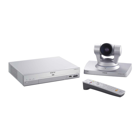
- Page 1 HD VISUAL COMMUNICATION SYSTEM PCS-XG80 PCS-XG80S SYSTEM INTEGRATION MANUAL 1st Edition Version 2.0...
- Page 2 électrique, d’incendie ou de blessure n’effectuer que les réparations indiquées dans le mode d’emploi à moins d’être qualifi é pour en effectuer d’autres. Pour toute réparation faire appel à une personne compétente uniquement. PCS-XG80...
-
Page 3: Table Of Contents
Table of Contents 1. Installation 3. Maintenance 1-1. Layout Information for PCS-XG80/XG80S ....1-3 3-1. Updating of Software ............3-1 1-1-1. Simple Connection ..........1-3 3-1-1. Web Version-upgrade ..........3-1 1-1-2. Camera Connection..........1-4 3-1-2. Updating Using Memory Stick ......3-5 1-1-3. -
Page 5: Installation
You must turn off the power to the HD visual Communication System before attempting to connect the camera to the system using the supplied camera cable. Otherwise, the camera and/or system may be damaged, or the picture may not be displayed. PCS-XG80... - Page 6 Installation Flowchart Preparation at <Refer to “1-1. Layout information for PCS-XG80/XG80S”> location of installation Unpacking <Refer to “1-1-1. Simple Connection”> Check of supplied accessories <Refer to “3-8. Replacing the Batteries”> System connections <Refer to “1-2. System Connections”> Turn on the power to the system <Refer to “2-1-1.
-
Page 7: Layout Information For Pcs-Xg80/Xg80S
1-1. Layout Information for PCS-XG80/XG80S 1-1-1. Simple Connection Making a “simple connection” To start video conferencing by making a “simple connection”, connect the cables to the green connectors, as shown below. * Supplied * Supplied cable * Supplied ... -
Page 8: Camera Connection
Installing the camera on a desk Place the camera on a fl at surface whenever possible. In extreme circumstances, you may place the cam- era on an inclined surface provided the inclination does not exceed ?15 degrees, to ensure that the pan/tilt operates correctly. PCS-XG80... - Page 9 This is used for VISCA connection to 2nd camera. When a second camera is connected with the HD Visual Communication System, connect the VISCA cable from the fi rst camera with the VISCA IN of the second camera. Please refer to “Connecting HD camera as 2nd Camera”. (page 1-9) PCS-XG80...
- Page 10 Pr_CAM 1.5C-2 V Pr_CAM(RET) Pr_CAM(RET) TXD(for external camera) RXD(for external camera) AWG #24 +19.5 V +19.5 V Twisted pair LVDS_RXD+ LVDS_TXD+ AWG #28 LVDS_RXD_ LVDS_TXD_ Twisted pair LVDS_TXD+ LVDS_RXD+ AWG #28 LVDS_TXD_ LVDS_RXD_ AWG #24 Shield Shield Shell Shell PCS-XG80...
- Page 11 MIC(A1/A3) 1(R) 2(L) DC 19.5V (PLUG IN POWER) AUDIO 1 IN AUDIO OUT REC OUT 1-EXT-2 Breakout cable is separately required. (For detail, contact your local Sony Sales Office/Service Center.) EVI-HD1 Breakout cable Shell AWG#28 AWG#28 AWG#28 AWG#26 AWG#26 To PCS-XG80S...
- Page 12 1-EXT-2 AUDIO 1 IN AUDIO OUT REC OUT 1-EXT-2 (PLUG IN POWER) (PLUG IN POWER) Breakout cable is separately required. (For detail, contact your local Sony Sales Office/Service Center.) Breakout Breakout cable cable BRC-H700 BRC-Z700 1 2 3 4 5 6 7 8 9...
- Page 13 Ver. 2.0 and later support the saving of thumbnails together with the camera preset settings. When the preset settings are recalled from the Communication System, the system automatically switches from the 1st to the 2nd camera (or from the 2nd to the 1st camera). PCS-XG80...
-
Page 14: Microphone Connection
PCS-XG80S, pay careful attention to the positioning guidelines described below. PCS-A1, PCSA-A3 microphone layout The positioning of the PCS-A1, PCSA-A3 microphones with the PCS-XG80/XG80S is the same as with other models in the PCS series. For details, refer to the Operating Instructions. - Page 15 *1 “Stereo or Monaural” depends on the setting of Input Mode/Output Mode of far end point. 3 m or less Loud 0.5 m to 1.5 m speaker Loud speaker PCS-A1 x 2 * Place each loud speaker at least 1.5 m from the PCS-A1. 1-11 PCS-XG80...
- Page 16 Be particularly careful when setting up the PCSA-A7 microphones, referring to the layout shown below. Position the PCSA-A7 microphone at least 1.5 m (5 ft.) from the loud speaker. Otherwise echo is likely to be a problem. PCS-XG80/XG80S Loud speaker PCSA-A7 Notes on placing the PCSA-A7 microphones .
-
Page 17: Audio Specifi Cations And Settings
1 kZ or less +6 dBs _14 dBs REC OUT L/R RCA Male 22 kHz 1 kZ or less +9 dBs max _11 dBs AUDIO 2 IN L/R RCA Male 22 kHz 47 kZ or more, (max: clip level) unbalanced 1-13 PCS-XG80... - Page 18 Do not activate the TV’s surround sound feature as it may prevent the echo canceller of the Commu- nication System from functioning properly and thus produce an unexpected sound. During communi- cation, set the volume on the Communication System to the appropriate level. Do not adjust the volume on the TV monitor. 1-14 PCS-XG80...
- Page 19 G.711 G.711 G.711 G.711 G.711 Mono Mono Mono Mono G.722 G.711 G.722 G.722 G.711 G.722 G.711 G.722 G.711 G.711 G.728 G.711 G.728 G.711 G.728 G.728 G.711 G.711 G.728 G.711 G.711 G.711 G.711 G.711 G.711 G.711 G.711 G.711 G.711 1-15 PCS-XG80...
- Page 20 “Audio Output Delay” set for the remote party. The optimum “Audio Output Delay” setting is adjusted for each remote party according to the individual usage circumstances, so it is recommended to use the “Default” value for “Audio Input Delay Setting”. 1-16 PCS-XG80...
- Page 21 MIC and AUX settings, refer to “2-2-2 Other Setup: To set up audio input and echo canceller”. Right and left can be reversed (Setting of “Audio Input” = MIC) MIC (A1/A3), AUDIO 1 IN, AUDIO 2 IN Camera Loud Speaker Loud Speaker Reversed PCS-XG80 Sender side Transmitting Receiver side PCS-XG80 Monitor Loud Speaker Loud Speaker...
- Page 22 Right and left not reversed (Setting of “Audio Input” = AUX) AUDIO 1 IN, AUDIO 2 IN Camera Loud Speaker Loud Speaker Not reversed PCS-XG80 Sender side Transmitting Receiver side PCS-XG80 Monitor Loud Speaker Loud Speaker 1-18 PCS-XG80...
-
Page 23: Echo Canceller
A stereo echo canceller function is supported for external inputs “AUDIO 1 IN” and “AUDIO 2 IN”. Refer to “Notice of external microphone usage” in “1-1-4. Audio Specifi cations and Settings” and “To set up audio input and echo canceller” in “2-2-2. Other Setup”. 1-19 PCS-XG80... -
Page 24: Monitor Connection
DVI-HDMI conversion adaptor/cable (commercially available) is required. Use a conversion adaptor/cable that conforms to HDMI standard. Verifi cation is needed before use. DVI cannot transmit digital audio signal through a single cable, so connect the audio output to the loud- speaker input. 1-20 PCS-XG80... -
Page 25: Pen Tablet
. Supported TABLET model is only Wacom “Bamboo” (MTE450). . The cable length which is attached by WACOM is 1.5 m (5 ft.). . If you use another longer cable except the attached one or use USB Hub, verifi cation is needed before use. 1-21 PCS-XG80... -
Page 26: Remote Commander And Pairing
PRESENTATION PRESENTATION LAYOUT LAYOUT VIDEO INPUT CAMERA VIDEO INPUT CAMERA VOLUME ZOOM VOLUME ZOOM ENTER ENTER RETURN TOOLS RETURN TOOLS BACK BACK CONNECT SPACE DISCONNECT CONNECT SPACE DISCONNECT PQRS WXYZ PQRS WXYZ TONE TONE ON/OFF ON/OFF PCS-RF1 PCS-RF1 1-22 PCS-XG80... - Page 27 . If you have lost the remote commander or if it no longer works, obtain a replacement and perform pairing again. . When the camera unit is to be paired with the Remote Commander and then installed in a high location, per- form the pairing before the installation. 1-23 PCS-XG80...
-
Page 28: Two Serial Ports On Pcs-Xg80S
Front: MAINTENANCE port LAN 1 ALERT LAN 2 ALERT OPEN OPEN VIDEO IN AUDIO 2 IN MAINTENANCE For taking a debug log/For engineering maintenance . bps: 115200 . Data bit: 8 . Parity: None . Stop bit: 1 1-24 PCS-XG80... - Page 29 Serial connector pin assignment 2 ..Recieve Data (RxD) 3 ..Transmit Data (TxD) 5 ..Signal GND RS-232C RX Buffer RS-232C TX Buffer D-sub 9pin male PCS-XG80S side 1-25 PCS-XG80...
-
Page 30: System Connections
SIP. Connection to a SIP server through the 2 (LAN2) connector is not available. . The REC OUT jack is used to make an audio recording of a communication. This is not used during regular communication. 1-26 PCS-XG80... -
Page 31: Pcs-Xg80 Connection Using Sip
1-2-2. PCS-XG80 Connection Using SIP The SIP function of the PCS-XG80/XG80S is not regarded as optional software (PCSA-SP1) but is supported as a standard function. Only 1 (LAN1) is used for the SIP function of this equipment. Note that 720 60fps/1080i mode is not supported. -
Page 32: System Connection Via An Isdn
To a wall outlet VGP-AC19V15 To HDMI IN AC adaptor (supplied) TV monitor (not supplied) To a wall outlet The REC OUT jack is used to make an audio recording of a communication. This is not used during regular conferences. 1-28 PCS-XG80... -
Page 33: System Confi Guration Using Two Ip Connections
DNS Server setting) NAT, H.460 Gatekeeper SIP Server SNMP Trap Destination Shared Phone Book AMX Device Discovery Multicast Streaming IPv6 Items that are effective for both LAN1 Port Numbers (TCP/UDP) and LAN2 by setting one Auto Answer Reject Answer 1-29 PCS-XG80... -
Page 34: Ipv6
POWER/STANDBY POWER/STANDBY POWER/STANDBY POWER/STANDBY POWER/STANDBY POWER/STANDBY PCS-XG80S HD Visual Communication System PCSA-CXG80 HD Camera Unit PCS-RF1 Remote Commander TV monitor (not supplied) PCS-A1 microphone HD MCU software PCSA-MCG80 (Commercially available) 1-30 PCS-XG80... - Page 35 PCS-XG80S HD Visual Communication System PCSA-CXG80 HD Camera Unit PCS-RF1 Remote Commander TV monitor (not supplied) PCS-A1 microphone HD MCU software PCSA-MCG80 (Commercially available) ISDN unit PCSA-B384S (Commercially available) or PCSA-B768S (Commercially available) 1-31 PCS-XG80...
- Page 36 PCS-XG80S HD Visual Communication System PCSA-CXG80 HD Camera Unit PCS-RF1 Remote Commander TV monitor (not supplied) PCS-A1 microphone HD MCU software PCSA-MCG80 (Commercially available) ISDN unit PCSA-B384S (Commercially available) or PCSA-B768S (Commercially available) 1-32 PCS-XG80...
-
Page 37: Multipoint Connection (Screen Display)
. Five sub-terminals are connected to the main terminal of the MCU. . All terminals are PCS-XG80s. . “Packet Resend Request (ARQ)” is set to “On”. Basic connection (PCS-XG80 only over IP connection, CP mode) 512 x 288 WCIF 1280 x 720 HD... - Page 38 Basic connection (PCS-XG80 only over IP connection, VA mode) Broadcasted by Main-terminal 512 x 288 WCIF 1280 x 720 HD 720HD Broadcaster Main terminal 10 Mbps Sub-terminal 2 Mbps 2 Mbps 2 Mbps 2 Mbps 2 Mbps 720HD 720HD 720HD...
- Page 39 Cascaded connection (PCS-XG80 only over IP connection, VA mode) Broadcasted by Main-terminal 10 Mbps 10 Mbps 512 x 288 WCIF Broadcaster WCIF WCIF 2 Mbps Sub-terminal Main Main terminal terminal 2 Mbps 2 Mbps 2 Mbps 2 Mbps Sub-terminal 2 Mbps...
- Page 40 When a terminal over ISDN joins (PCS-XG80 only, CP mode) 512 x 288 WCIF 1280 x 720 HD 720HD Main terminal 10 Mbps Sub-terminal 2.5 Mbps 2.5 Mbps 2.5 Mbps 2.5 Mbps 720HD 720HD 720HD 720HD When a terminal connected over...
- Page 41 When a terminal over IP joins at a low-bit rate (PCS-XG80 only over IP, CP mode) 512 x 288 WCIF 1280 x 720 HD 720HD Main terminal 10 Mbps Sub-terminal 2.5 Mbps 2.5 Mbps 2.5 Mbps 2.5 Mbps 720HD 720HD...
- Page 42 When an SD model joins (PCS-XG80 + PCS-G50 over IP, CP mode) 512 x 288 WCIF 1280 x 720 HD 720HD Main terminal 10 Mbps Sub-terminal 2.5 Mbps 2.5 Mbps 2.5 Mbps 2.5 Mbps 720HD 720HD 720HD 720HD When an SD model joins...
- Page 43 When PCS-HG90 joins (PCS-XG80 + PCS-HG90 over IP connection) 512 x 288 WCIF 1280 x 720 HD 720HD Main terminal 10 Mbps 3.3 Mbps Sub-terminal 3.3 Mbps 3.3 Mbps 720HD 720HD 720HD When PCS-HG90 joins 512 x 288 WCIF 1280 x 720 HD...
- Page 44 819 kbps MPEG4-AAC VO: Voice only . When the PCS-HG90/PCS-G50 or other than the PCS-XG80 (including other companies’ products) joins the conference, a maximum rate of 4 Mbps can be attained. The PCS-HG90 is a voice terminal. The dialing order of the PCS-HG90 or any SD terminal does not affect the above operation.
-
Page 45: To Connect A Video Equipment For Input
To audio output Video cable (not supplied) To VIDEO IN To video output With regard to the setting of the linkage between video and audio, refer to the Operating Instructions (Setup → Video3 → Link to Audio Input). 1-41 PCS-XG80... -
Page 47: Setup/Alignment And Video Mode
2-1-1. Turning On the System During the system boot up sequence, the display monitor is as below. It takes about 90 seconds. 2-1-2. Turning Off the System During the system shutdown sequence, the display monitor is as below. It takes about 1 minute. PCS-XG80... -
Page 48: Initial Setup And Other Setup
2. Use the [(]/[)] button on the Remote Commander to select the language to be used for the on-screen menus and messages. About the supported languages. refer to the Operating Instructions. 3. Use the [(]/[)] button on the Remote Commander to select “Save”, then press the [ENTER] button. The setup wizard is restored. PCS-XG80... - Page 49 When you enter a Number/Address, a Dial menu that is custom- ized to this selected Line I/F is displayed. 3. Use the [(]/[)] button on the Remote Commander to select “Save”, then press the [ENTER] button. The setup wizard is restored. PCS-XG80...
- Page 50 HDMI + RGB: Outputs the video signal to the external equipment from the HDMI OUT and RGB OUT connectors. Do not select “HDMI + RGB” when a single RGB monitor is used, or the setup menu will become unavailable. Should this occur, refer to Section 1-1-6 “Notes on monitor connections and settings” and then perform recovery. PCS-XG80...
- Page 51 S VIDEO: Selects the picture from the external equipment connected with the S VIDEO IN input. RGB: Selects the picture from the external equipment connected with the RGB IN input YPbPr: Selects the picture from the external equipment connected with the YPbPr input. PCS-XG80...
-
Page 52: Other Setup
To set 1080i mode, Setup → Administrator → 1080i Mode. Off: Not to use 1080i video format. On: To use 1080i video format. When set to “On” from “Off”, the system reboots automatically. (Also when set to “Off” from “On”, the system reboots automatically.) PCS-XG80... - Page 53 When AUDIO 1 IN is used as AUX, this signal does not go through the echo canceller block. If “Audio Input” is “AUX”, you cannot set “Echo Canceller” fi eld. In this case, the input level will be the line level. PCS-XG80...
- Page 54 To set up RF Remote Control Reception, “Setup → General1 → RF Remote Control Reception”. System: Receives the RF signal with the receiver on the Communication System. Camera: Receives the RF signal with the receiver on the PCSA-CXG80 Camera Unit. The Remote Commander and the Communication System are paired at the factory. PCS-XG80...
-
Page 55: Video Mode And Bandwidth
2-3. Video Mode and Bandwidth 2-3-1. 1080i Mode The PCS-XG80/80S can transmit and receive high-resolution (1920 pixels x 1080 lines), 60 fi elds/sec video pictures in 1080i mode. Full screen display HD 1080i 1080i Single stream LAN 1 ALERT LAN 2 ALERT... -
Page 56: P And Other Mode
1536k W4CIF/ W432P/ 1024k W4CIF/30 W432P/ W432P/ 768k W432P/30 WCIF/ WCIF/ WCIF/ WCIF/ WCIF/ 512k WCIF/30 384k WCIF/ WCIF/ WCIF/ WCIF/ WCIF/ WCIF/ WCIF/ WCIF/ 256k WCIF/15 128k WCIF/ WCIF/ WCIF/ WCIF/ WCIF/ WCIF/ WCIF/ WCIF/ WCIF/ WCIF/10 2-10 PCS-XG80... - Page 57 WCIF/15 AUTO Individual Setting Setting Resolution AUTO W4CIF W432P WCIF Bit Rate (bps) Frame Rate AUTO W4CIF/ W4CIF/ W4CIF/ W432P/ W432P/ W432P/ WCIF/ WCIF/ 512k WCIF/30 WCIF/ 256k WCIF/ WCIF/ WCIF/ 128k WCIF/ WCIF/ WCIF/ WCIF/ WCIF/ WCIF/15 2-11 PCS-XG80...
-
Page 59: Maintenance
Confi rming the software version from Machine Information Refer to Section 3-4-4. Opening the Web Page Enter the IP address assigned to the PCS-XG80/XG80S in the address line of your browser such as Inter- net Explorer. The format of an address is: http://XXX.XXX.XXX.XXX/... - Page 60 How to Use [Version Up] Page 1. Store the update fi le to your PC. 2. When you click [Setup] on the top part of the page, [Version Up] appears on the lower left of the page, then click [Version UP]. PCS-XG80...
- Page 61 3. Click [Reference] and select the software you want to upgrade, then click the [upload]. PCS-XG80...
- Page 62 . Make sure that the power stays on until update sequence ends, otherwise the system may not boot up again. . Use the secure and stable network. The use of a wireless LAN is not recommended. . This way via Web should be used for upgrading. It cannot be used for downgrading. PCS-XG80...
-
Page 63: Updating Using Memory Stick
Center front LED . For details on how to save system software to the Memory Insert a Memory Stick into Stick, contact your local Sony Memory Stick slot of the Sales Office/Service Center. PCS-XG80. . Use a Memory Stick with a capacity of 512MB and above. -
Page 64: Upgrading Using Ftp (No Support)
If red LED of software-key lights, it is already used and it cannot be used for installation and for memory. Optional Software . PCSA-DSG80: HD Data Solution Software (for H.239 video and presentation data) . PCSA-MCG80: HD MCU Software PCS-XG80... -
Page 65: Confi Rmation Procedure Of Local Terminal Operation Using Self-Loop
Operation procedure 1. Press the power switch on the Communication System to turn it on. Home menu will appear on the monitor screen. 2. Confi gure the setup menus as necessary. PCS-XG80... - Page 66 Select the Bit rate and press “Connect”. The menu disappears and the message “Dialing” appears on the monitor screen. A self-loopback is start- ed, and the message “Session Connected” appears. Confi rm the camera picture displayed on the monitor. PCS-XG80...
-
Page 67: Description On Status Menu
Send a traceroute command to display the results of the check for HOP (number of routers passed through to reach the remote site) and total RTT (to-and-fro delay). Start Measurement: Select this button to start a network routing check. Previous: Select this button to restore a Machine Status menu. PCS-XG80... -
Page 68: Communication Mode Status
Displays in real time the number of connected lines and their transfer rates. Line I/F: Displays the line interface being used. Camera Control: Displays whether the unit is ready to operate both cameras. H239: Displays whether the unit is ready to use the H.239 presentation mode. 3-10 PCS-XG80... -
Page 69: Lan Line Status
(Above example shows that 18 packets are lost and all lost packets are recov- ered by QoS. ) Right columns: Displays the number of received packets. Packet loss indicator will be displayed at every count of packet loss. Packet Loss 3-11 PCS-XG80... -
Page 70: Machine Information
You can confi rm the software version and optional software status and MAC address and IP address, etc. by Machine information. 1. Press the [TOOLS] button on the Remote Commander. 2. Use the [(]/[)] button on the Remote Commander to select “Machine Status”, then press the [ENTER] button. The “Machine Status” menu appears. 3-12 PCS-XG80... - Page 71 3. Use the [(]/[)] button on the Remote Commander to select “Machine Information”, then press the [ENTER] button. The Machine Information menu appears. 4. Press the [Next] button, then next page appears. 3-13 PCS-XG80...
-
Page 72: Peripheral Status
Requested, Registration Confi rmed, Registration Failed, Registra- tion Rejected, Registration Timeout, Unregistration, Requested and Unreg- istration Confi rmed. First Camera: Displays the name of the fi rst camera. Second Camera: Displays the name of the second camera. 3-14 PCS-XG80... -
Page 73: Description On Service Menu
You can input command and load/save Phone Book and Setup and save several kinds of logs. 3-5-1. Displaying the Service Menu 1. Use the [(]/[)]/[&]/[*] button to select “Home” in the Setup menu, then press “7” then “2” on the Remote Commander. 2. Then Service menu appears. 3-15 PCS-XG80... -
Page 74: Description On Service Menu
Forcibly fi xes the HDMI output resolution to 1080i. Use thiscommand to check whether the HDMI moni- tor being used iscompatible with 1080i video. NOSCALE Returns the presentation video displayed on the HDMI outputmonitor to the size used for Ver. 2.0 and earlier versions. 3-16 PCS-XG80... - Page 75 Save Operation Log: Use to save the operation log to Memory Stick. Operation log is a record of opera- tion made by remote commander, external command, and cgi command (Web interface). Save Call Log: Use to save the call log to Memory Stick. 3-17 PCS-XG80...
-
Page 76: How To Take Logs
2008-06-02 12:08:38:526|info |1078.1078|codecif |BA: FrameCount0 0 2008-06-02 12:08:38:526|info |1078.1078|codecif |BA: FrameRate 300 Index 1 2008-06-02 12:08:38:526|info |1078.1078|codecif |BA:vin[0]:requestFormat:15,Capture Foramt7,capture Mode 3 2008-06-02 12:08:38:526|info |1078.1078|codecif |BA:z_vcap_m[0]:VCAP_Mode change 0->3 2008-06-02 12:08:38:526|info |1078.1078|codecif |BA:z_vcap_m[0]:Video Driver initialized.0x80ab7c60 2008-06-02 12:08:38:526|info |1078.1078|codecif |BA:z_vcap_m[0]:Video Driver IntCb initialized. 3-18 PCS-XG80... - Page 77 Data length: 8 bits STOP bit: 1 bit Parity bit: None (RS-232 cross cable) VISCA OUT TERMINAL PCS-XG80 Personal computer When obtaining the system log using the terminal software and a serial cable, the entire system log may not be collected. 3-19 PCS-XG80...
-
Page 78: Operation Log
Open the web page and then select “Download” in the left column. Then, click “Download” to the right of “Save Operation Log”. Download of the operation log starts. 3-20 PCS-XG80... -
Page 79: Call Log
Before starting the web interface, refer to “Opening the Web Page” in “3-1-1 Web Version-upgrade”, or refer to the operating instructions supplied with the unit. Open the web page and then select “Download” in the left column. Then, click “Download” to the right of “Save Call Log”. Download of the call log starts. 3-21 PCS-XG80... -
Page 80: Network Trouble Check
Check the difference in the sequence number between Step 4 Packet losses occurred the Sender and Receiver between switch (HUB) and PCS-XG80 different? Packet losses occurred Packet losses occurred between switch (HUB) between the Sender switch and PCS-XG80 and the Receiver switch... -
Page 81: Description Of Each Test
The procedure and an explanation of how to read the log are given below. If lost packets are noted in the “OPLOG” lines of the log, go to Step 2. When no packets have been lost, this indicates that there is no problem in the network or PCS-XG80. Procedures: 1. - Page 82 The checking procedure is described in Step 3 and the subsequent steps. Preparations: Connect a mirroring switch between the PCS-XG80 and the network switch, and then connect a PC for packet capture to the monitor port of the mirroring switch.
- Page 83 If there is no difference between the logs, it indicates that the packet loss is being caused by a PCS-XG80 internal problem or an “Ethernet duplex mismatch problem” between the PCS-XG80 and the switch.
- Page 84 Fig.3 Comparing sender-side log with receiver-side log 3-26 PCS-XG80...
-
Page 85: Replacing The Batteries
+ side fi rst may damage the insulated fi lm covering the batteries and cause a short circuit. . Once pairing is established between the units, it will not be erased even if the batteries are replaced. 3-27 PCS-XG80... - Page 88 PCS-XG80 (SY, CN) Printed in Japan Sony Corporation PCS-XG80S (SY, CN) E 2008. 12 22 9-968-450-01 ©2008...
Need help?
Do you have a question about the Ipela PCS-XG80 and is the answer not in the manual?
Questions and answers