Graco ProMix PD2K Operation
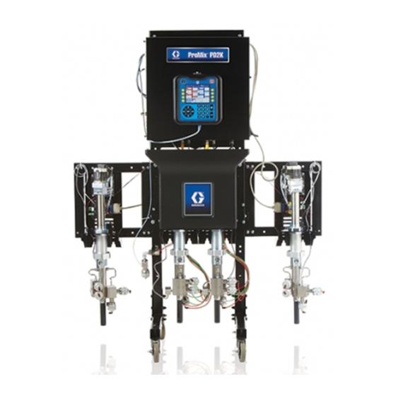
Dual fluid panel, electric proportioner for automatic spray applications
Hide thumbs
Also See for ProMix PD2K:
- Operation (180 pages) ,
- Repair parts (82 pages) ,
- Installation manual (62 pages)
Table of Contents
Advertisement
Quick Links
Operation
ProMix®
ProMix® PD2K
ProMix®
PD2K Dual
PD2K
Electric Proportioner
Proportioner for
Electric
Electric
Proportioner
Spray
Spray Applications
Spray
Applications
Applications
Electronic positive
positive displacement
displacement proportioner
Electronic
Electronic
positive
displacement
Advanced Display
Display Module.
Module. For
Advanced
Advanced
Display
Module.
Important Safety
Safety Instructions
Important
Important
Safety
Read all warnings and instructions in this manual and in your PD2K
installation, repair, and associated component manuals. Save these
instructions.
See page 4for model part numbers and
approvals information.
Dual Fluid
Dual
Fluid Panel
Fluid
for Automatic
Automatic
for
Automatic
proportioner for
for two
proportioner
for
For professional
professional use
use only.
For
professional
use
Instructions
Instructions
PROVEN QUALITY. LEADING TECHNOLOGY.
Panel
Panel
two- - - component
component materials.
materials. Automatic
two
component
materials.
only.
only.
3A4486D
Automatic system
system with
with
Automatic
system
with
EN
Advertisement
Table of Contents

Related Manuals for Graco ProMix PD2K


Summary of Contents for Graco ProMix PD2K
- Page 1 Operation ProMix® ProMix® PD2K ProMix® PD2K Dual PD2K Dual Fluid Dual Fluid Panel Fluid Panel Panel Electric Proportioner Proportioner for for Automatic Automatic Electric Electric Proportioner Automatic 3A4486D Spray Spray Applications Spray Applications Applications Electronic positive positive displacement displacement proportioner proportioner for for two two- - - component...
-
Page 2: Table Of Contents
Contents Contents Contents Related Manuals ..........3 Spray Screen..........64 Fill Screen ........... 65 Models..............4 Usage Screen..........66 Warnings ............. 6 Jobs Screen ..........67 Errors Screen ..........67 Important Isocyanate (ISO) Information ....9 Events Screen ..........67 Important Acid Catalyst Information ..... -
Page 3: Related Manuals
Related Manuals Related Related Manuals Related Manuals Manuals Current manuals are available at www.graco.com. Manual Manual Manual No. Description Description Description Manual Manual No. Manual Description Description Description 332709 ProMix PD2K Proportioner for 333282 Color Change and Remote Mix Automatic Spray Applications, Manifold Kits, Instructions —... -
Page 4: Models
Models Models Models Models See Figs. 1–6 for component identification labels, including approval information and certification. Part Part Part No. Series Series Series Maximum Maximum Air Maximum Air Working Working Working Maximum Maximum Fluid Maximum Fluid Fluid Working Working Working Location Location of of of PD2K Location... - Page 5 Models Figure 3 Model AC2002 & AC4002 (High Pressure) Identification Label Figure 4 Non-Intrinsically Safe Color Change Control (Accessory) Identification Label Figure 5 Intrinsically Safe Color Change Control (Accessory) Identification Label Figure 6 Pump Expansion Kit (Accessory) Identification Label PART NO. DATE / SERIES RECOGNIZED COMPONENT...
-
Page 6: Warnings
Warnings Warnings Warnings Warnings The following warnings are for the setup, use, grounding, maintenance, and repair of this equipment. The exclamation point symbol alerts you to a general warning and the hazard symbols refer to procedure-specific risks. When these symbols appear in the body of this manual, refer back to these Warnings. Product-specific hazard symbols and warnings not covered in this section may appear throughout the body of this manual where applicable. - Page 7 Warnings WARNING WARNING WARNING INTRINSIC SAFETY SAFETY INTRINSIC INTRINSIC SAFETY Intrinsically safe equipment that is installed improperly or connected to non-intrinsically safe equipment will create a hazardous condition and can cause fire, explosion, or electric shock. Follow local regulations and the following safety requirements. •...
- Page 8 Warnings WARNING WARNING WARNING PERSONAL PROTECTIVE PROTECTIVE EQUIPMENT EQUIPMENT PERSONAL PERSONAL PROTECTIVE EQUIPMENT Always wear appropriate personal protective equipment and cover all skin when spraying, servicing equipment, or when in the work area. Protective equipment helps prevent serious injury, including long-term exposure;...
-
Page 9: Important Isocyanate (Iso) Information
Important Isocyanate (ISO) Information Important Isocyanate Isocyanate (ISO) (ISO) Information Information Important Important Isocyanate (ISO) Information Moisture Sensitivity Sensitivity of of of Isocyanates Isocyanates Moisture Moisture Sensitivity Isocyanates Isocyanates (ISO) are catalysts used in two component materials. Exposure to moisture (such as humidity) will cause ISO to partially cure;... -
Page 10: Important Acid Catalyst Information
Important Acid Catalyst Information Important Acid Acid Catalyst Catalyst Information Information Important Important Acid Catalyst Information The PD2K AC4002 Proportioner is designed for acid catalysts (“acid”) currently used in two-component, wood-finishing materials. Current acids in use (with pH levels as low as 1) are more corrosive than earlier acids. More corrosion-resistant wetted materials of construction are required, and must be used without substitution, to withstand the increased corrosive properties of these acids. -
Page 11: General Information
General Information General Information Information General General Information • Reference numbers and letters in parentheses • To protect the screens from paints and solvents, in the text refer to numbers and letters in the clear-plastic protective shields (10 per pack) are illustrations. -
Page 12: Advanced Display Module (Adm)
6. The USB flash drive window automatically opens. If it does not, open the USB flash drive from within Windows® Explorer. 7. Open Graco folder. 8. Open system folder. If downloading data from more than one system, there will be more than one folder. - Page 13 Graco folder. Each folder is the UPLOAD folder on the USB flash drive. This will labeled with the corresponding serial number of prevent inadvertently overwriting any future setup the ADM.
- Page 14 Advanced Display Module (ADM) ADM Keys Keys and and Indicators Indicators Keys Indicators NOTICE NOTICE NOTICE To prevent damage to the softkey buttons, do not press the buttons with sharp objects such as pens, plastic cards, or fingernails. Table 1 1 1 : : : ADM ADM Keys Keys and and Indicators...
- Page 15 Advanced Display Module (ADM) Soft Key Key Icons Icons Soft Soft Icons The following icons appear in the ADM display, Function Function Function directly to the left or right of the soft key which activates that operation. Press to engage solvent NOTICE NOTICE NOTICE...
-
Page 16: Navigating The Screens
Advanced Display Module (ADM) Screen Icons Icons Screen Screen Icons Function Function Function As you move through the screens, you will notice Appears on the User ID that icons are used frequently to simplify global Keyboard screen. Use to communication. The following descriptions explain erase one character at a what each icon represents. -
Page 17: Pre-Operation Tasks
Power Go through the Pre-Operation Checklist daily, before 1. Turn the AC Power Switch (P) ON (I = ON, each use. 0 = OFF). 2. The Graco logo will display while the system Checklist ✔ ✔ ✔ Checklist Checklist initializes, followed by the Home screen. -
Page 18: Valve Settings
Pre-Operation Tasks Initial System System Setup Setup Valve Settings Settings Initial Initial System Setup Valve Valve Settings Dose valves and purge valves are factory set with the 1. Change optional setup selections to hex nut (E) 1-1/4 turns out from fully closed. desired parameters, as described in Setup Mode Screens, page 2. -
Page 19: Pressure Relief Procedure
Pressure Relief Procedure Pressure Relief Relief Procedure Procedure Pressure Pressure Relief Procedure With Color Color Change Change With With Color Change Follow the Pressure Pressure Relief Pressure Relief Procedure Relief Procedure Procedure whenever you see this symbol. NOTE: The following procedure relieves all fluid and NOTE: NOTE: air pressure in the system. -
Page 20: Operation Using Advanced Display Module
Operation Using Advanced Display Module (ADM) Operation Using Using Advanced Advanced Display Display Module Module (ADM) (ADM) Operation Operation Using Advanced Display Module (ADM) Prime Prime and Prime and Fill Fill Fill the the System System System Pre - - - Fill Fill the Fill the Pump... -
Page 21: Purging
Operation Using Advanced Display Module (ADM) Purging Purging Purging Flush Flush the Flush the System System System To purge one color and fill with a new color, see Color Change, page Flush Flush Flush Mixed Mixed Mixed Material Material Material To avoid fire and explosion, always ground equipment and waste container. -
Page 22: Shutdown
Operation Using Advanced Display Module (ADM) Color Change Change System System Color Color Change System 8. Hold a metal part of the gun firmly to a grounded metal pail. Trigger the gun until clean solvent 1. Relieve the pressure. dispenses. Pressure Relief Procedure, page 9. - Page 23 Control Set 4-20 mA Input system if a proper gun trigger signal is provided. It is Point #1 not intended to be the main mode of control. Graco Control Set 4-20 mA Input recommends that Manual Override be disabled Point #2 during normal operation to avoid driving the system in a way that conflicts with the automation sequence.
-
Page 24: Operation Using A Programmable Logic
Mix Unit. The ProMix PD2K scales the set point pumps regardless of the current operating mode. linearly from 0 to the Max Set Point setting (see... -
Page 25: Discrete I/O
Operation Using a Programmable Logic Controller (PLC) Discrete I/O I/O Connections Connections on on EFCM EFCM Discrete Discrete Connections EFCM Figure 12 Gun Trigger Input #1 Gun Trigger Input #2 Analog Set Point Input #1 Analog Set Point Input #2 Safety Interlock Input 3A4486D... -
Page 26: Details
Operation Using a Programmable Logic Controller (PLC) Communication Gateway Gateway Module Module (CGM) (CGM) Details Details Communication Communication Gateway Module (CGM) Details CGM Overview Overview Overview Installation Installation Installation Kit Part No. Field Bus Manual Part Part Field Field Manual Manual The CGM provides a control link between the PD2K system and a selected fieldbus. - Page 27 Outputs Outputs The ProMix PD2K Network Outputs are Read-Only and should be treated as inputs to a PLC or other networking device. These registers provide various system and component status, measurement, and set point values. See Network Output Data Map (Read Only), page...
- Page 28 Operation Using a Programmable Logic Controller (PLC) OUTPUT OUTPUT REGISTER OUTPUT REGISTER REGISTER 01 01 and and 27: 27: Event Event Flag Event Flag Flag This data register is valid only for systems configured to use the discrete inputs for the Gun Triggers. Gun Trigger Signal, page 71 The Event Flag register provides indication when an event (Alarm or Deviation) has occurred that requires...
- Page 29 Operation Using a Programmable Logic Controller (PLC) OUTPUT REGISTER REGISTER 10: 10: Actual Actual Pump Pump 1 1 1 OUTPUT REGISTER REGISTER 16 16 and and 42: 42: Active Active OUTPUT OUTPUT REGISTER Actual Pump OUTPUT OUTPUT REGISTER Active Flow Rate Rate Recipe Material Material B B B...
- Page 30 Operation Using a Programmable Logic Controller (PLC) OUTPUT REGISTER REGISTER 20 20 and and 46: 46: Active Active OUTPUT REGISTER REGISTER 24 24 and and 50: 50: Job OUTPUT OUTPUT REGISTER Active OUTPUT OUTPUT REGISTER Recipe Potlife Potlife Timeout Timeout Set Set Point Point Solvent Volume...
- Page 31 Operation Using a Programmable Logic Controller (PLC) Network Output Output Data Data Map Map (Read (Read Only) Only) Network Network Output Data (Read Only) Network Network Network Modbus Modbus Modbus Parameter Parameter Parameter Name Name Name Data Data Type Data Type Type Units...
- Page 32 Operation Using a Programmable Logic Controller (PLC) Network Modbus Parameter Name Name Data Type Type Units Range Network Network Modbus Modbus Parameter Parameter Name Data Data Type Units Units Range Range Output Output Output ID ID ID Register Register Register 0010 41020 Actual Pump 1 Flow...
- Page 33 Operation Using a Programmable Logic Controller (PLC) Network Network Network Modbus Modbus Modbus Parameter Parameter Parameter Name Name Name Data Data Type Data Type Type Units Units Units Range Range Range Output Output Output ID ID ID Register Register Register 0027 42002 Event Flag...
- Page 34 Operation Using a Programmable Logic Controller (PLC) Network Modbus Parameter Name Name Data Type Type Units Range Network Network Modbus Modbus Parameter Parameter Name Data Data Type Units Units Range Range Output Output Output ID ID ID Register Register Register 0050 42048 Job Solvent Volume...
- Page 35 These registers allow the user to control system operation and configure system settings remotely. Invalid values (i.e. out of bounds or not consistent with system configuration) will be ignored by the ProMix PD2K. All values must be written as integers. Floating point numbers are not supported.
- Page 36 • Write a value between 33 and 40 if priming a Catalyst pump. NOTE: NOTE: It is important that the user know which NOTE: material is assigned to each pump. An invalid selection will be ignored by the ProMix PD2K. 3A4486D...
- Page 37 It is recommended the job remotely. Write a ‘1’ to the register to command automation reset this register by writing a ‘0’ to it at the ProMix PD2K to flag a job complete. all other times to avoid inadvertently logging a job.* (See...
- Page 38 See Digital Inputs, page NOTE: Because timing is so critical for flow control NOTE: NOTE: Graco recommends that users provide a discrete input to minimize latency effects. Input Register 08 Gun Trigge r Discrete Signal...
- Page 39 Operation Using a Programmable Logic Controller (PLC) Network Input Input Data Data Map Map (Write/Read) (Write/Read) Network Network Input Data (Write/Read) Network Network Network Modbus Modbus Modbus Parameter Parameter Name Parameter Name Name Data Data Data Units Units Units Range Range Range Input...
- Page 40 Operation Using a Programmable Logic Controller (PLC) Network Network Network Modbus Modbus Modbus Parameter Parameter Parameter Name Name Name Data Data Data Units Units Units Range Range Range Input Input Input ID ID ID Register Register Register Type Type Type 0010 42100 uint32...
- Page 41 Operation Using a Programmable Logic Controller (PLC) Network Network Network Modbus Modbus Modbus Parameter Parameter Name Parameter Name Name Data Data Data Units Units Units Range Range Range Input Input Input ID ID ID Register Register Register Type Type Type 0026 43112 unit32...
- Page 42 Operation Using a Programmable Logic Controller (PLC) Operation Flow Flow Charts Charts Operation Operation Flow Charts NOTE: NOTE: NOTE: All flow charts reference registers for Mix Unit #1. For Mix Unit #2, reference the Network Maps for corresponding register indices. Purge Mode Mode Sequence Sequence...
- Page 43 Operation Using a Programmable Logic Controller (PLC) Purge Recipe Recipe Sequence Sequence Purge Purge Recipe Sequence Purge Recipe System Command Write ‘9’ to Input Re gis te r 00 No action taken. Either pumps are currently Is Mix Unit #1 in Standby running or an alarm condition or Pumps Of f? exists.
- Page 44 Operation Using a Programmable Logic Controller (PLC) Inactive Pump Pump Flush Flush and and Prime Prime Sequences Sequences Inactive Inactive Pump Flush Prime Sequences Write Flush Sequence # Write Prime Material # (1-5) to Input Register 05 (1-40) to Input Register 05 NOTE: Be sure to read to appropriate Output Register* Write...
- Page 45 Operation Using a Programmable Logic Controller (PLC) Line Fill Fill and and Flush Flush Sequences Sequences Line Line Fill Flush Sequences Write Material # Write Material # (1 - 40) to Input Register 05 (1 - 40) to Input Register 05 Write Line Flush Command Write Line Fill Command ‘10’...
- Page 46 Operation Using a Programmable Logic Controller (PLC) Color Change Change Sequence Sequence Color Color Change Sequence NOTE: If using Cus tom Ma pping for color cha nge va lve s , a nd the Inle t s ta ck is s e t to Write Go to Re c ip e Nu m b e r S ingle , the Ma te ria l Re a dy fla g ne e ds to be (0,1 - 30) t o Input Registe r 02...
- Page 47 Operation Using a Programmable Logic Controller (PLC) Recipe Change Change Alarm Alarm Recovery Recovery Sequences Sequences Recipe Recipe Change Alarm Recovery Sequences Read Status of Output Register 00 Output Register 00 = Output Register 00 = Output Register 00 = Output Register 00 = ‘13’? ‘14’?
- Page 48 Operation Using a Programmable Logic Controller (PLC) Mixing Sequence Sequence Mixing Mixing Sequence Mix Fill or Mix System Command W rite ‘4’ or ‘5’ to Input Register 00 System Mode = Standby: Mix Ready (Output Register 00 = ‘1 1’) No action taken.
- Page 49 Operation Using a Programmable Logic Controller (PLC) Alarm Clearing Clearing Sequence Sequence Alarm Alarm Clearing Sequence NOTE: If an alarm condition is active the System Mode will either be Pump Off or Standby: Alarm Clear Active Alarm (Output Register 00 = ‘1’ or ‘14’), Write ‘1’...
- Page 50 2. Once all arguments have been passed, write the command ID to INPUT REGISTER 29. 3. The ProMix PD2K will respond to a valid command by writing a 2 (Acknowledge) to OUTPUT REGISTER 61. 4. The ProMix PD2K will write appropriate return values to OUTPUT REGISTERS 52 – 60.
- Page 51 ASCII characters. The return registers will echo the arguments received. NOTE: NOTE: NOTE: The User ID character string must be terminated with a null character. Example: Write a User ID of “John Doe” to Mix Unit #1 of the ProMix PD2K. DCS Register Register Parameter Description...
- Page 52 Operation Using a Programmable Logic Controller (PLC) Write Recipe Recipe Write Write Recipe The Write Recipe command allows users to configure an entire recipe remotely. See Recipe Screen, page 76, for more details on recipes and recipe parameters. The return registers will echo the arguments received. NOTE: The recipe must be enabled via the ADM before it can be loaded for mixing.
- Page 53 Operation Using a Programmable Logic Controller (PLC) Write Flush Flush Sequence Sequence Write Write Flush Sequence The Write Flush Sequence command allows users to configure an entire flush sequence remotely. See Flush Screen, page 79, for more details of flush sequence parameters. The return registers will echo the arguments received.
- Page 54 Operation Using a Programmable Logic Controller (PLC) Write Material Material Ready Ready Flag Flag Write Write Material Ready Flag The Write Material Ready Flag command is used to signal to the PD2K that the upstream material management has the appropriate color/catalyst loaded at the inlet valve stack(s) of the pump(s) prior to a recipe change. This flag is only used when multiple materials for a pump are fed to the PD2K via a single valve at the inlet valve stack (i.e.
- Page 55 Operation Using a Programmable Logic Controller (PLC) Read Recipe Recipe Read Read Recipe The Read Recipe command returns all configured recipe parameters for a desired recipe number. The number of the recipe to be read is the only argument. Example: Read Mix Unit #1 Recipe 5 data as it is currently configured with Color = 3, Catalyst = 2 (34), Color Flush Sequence = 1, Catalyst Flush Sequence = 4, Mix Ratio Set Point = 3.25:1, Potlife = 35 min, and Mix Pressure Tolerance = 30%.
- Page 56 Operation Using a Programmable Logic Controller (PLC) Read Job Job Info Info Read Read Info The Read Job Info command is used to access data from any of the most recent 200 job logs. The argument is the chronological index of the job log, where 0 is the most recent job log and 199 is the 200 most recent.
- Page 57 Read Alarm Info The Read Alarm Info command allows remote access to any of the last 200 alarms logged by the ProMix PD2K. The chronological index argument is the of the alarm log, where 0 is the most recent alarm and 199 is the 200 most recent.
- Page 58 Read Event Info The Read Event Info command allows remote access to any of the last 200 events logged by the ProMix PD2K. chronological index The argument is the of the events log, where 0 is the most recent event and 199 is the 200 most recent.
- Page 59 Operation Using a Programmable Logic Controller (PLC) PLC Diagnostic Diagnostic Screens Screens Diagnostic Screens PLC Diagnostic Diagnostic Screens Diagnostic Screens 11 Screens These screens may be used to verify PLC communications by providing a real-time status of all Network Inputs and Outputs. This screen encapsulates all the registers used in the Dynamic Command Structure.
- Page 60 The ProMix PD2K smooth transition to flow control if the gun trigger system can control fluid flow by directly controlling signal returns.
- Page 61 NOTE: grayed-out on the screens are not currently active. Opening Opening Screen Opening Screen Screen At power up, the Graco logo will display for approximately 5 seconds, followed by the Home screen. Figure 18 Opening Screen Home Screen Screen Home...
-
Page 62: Run Mode Screens
Run Mode Screens Home Screen Screen Key Home Home Screen Description Details Description Description Details Details Date and Time Advanced Screen 1, page 92, to set. Menu Bar Run Screens. Use left and right arrow keys to scroll through the different Run screens: •... - Page 63 Run Mode Screens Description Description Description Details Details Details Spray Device Animation* Shows mixed material in the spray device and displays active recipe at the spray device. Gun animation changes to show: • • (Mix Fill) (Purge) • • (Mix With Gun Triggered) •...
- Page 64 Run Mode Screens Spray Screen Screen Spray Spray Screen NOTE: In normal operating mode, controlled by a NOTE: NOTE: PLC, the Spray Screen is display only. No changes can be made. This section provides information about the Spray Screen if Manual Override is enabled System Screen 1, page 68.
- Page 65 Run Mode Screens Fill Screen Screen Fill Fill Screen NOTE: NOTE: NOTE: This screen is visible only if Manual Override is enabled on System Screen 1, page The Fill screen displays the following information for the pump assigned to the current color: •...
- Page 66 Run Mode Screens Usage Screen Screen Usage Usage Screen The first Usage screen displays the current job usage of component A, B, A+B, and solvent (S). The second Usage screen displays grand total usage of component A, B, A+B, and solvent (S). Edits may be made only if Manual Override is enabled on System Screen 1, page 68.
-
Page 67: Errors Screen
Run Mode Screens Jobs Screen Screen Jobs Jobs Screen The Jobs screen displays the 200 most recent job numbers, recipes, Mix Unit, and A+B volumes in a log, with date, time, and User ID. Figure 34 Errors Screen, Edit Mode Events Screen Screen Events... -
Page 68: Setup Mode Screens
Setup Mode Screens Setup Mode Mode Screens Screens Setup Setup Mode Screens System Screen Screen 1 1 1 System System Screen Press on any Run screen to enter the Setup screens. System screen 1 includes the following fields which define your system. Most parameters on the Setup screens may be configured individually for each Mix Unit, while some are global. - Page 69 Setup Mode Screens System Screen Screen 2 2 2 System System Screen System screen 2 sets the following system operating The value will be a flow rate if Fluid Control is set parameters. to ‘Flow’, or a pressure if Fluid control is set to ‘Pressure’.
- Page 70 Setup Mode Screens System Screen Screen 3 3 3 System System Screen Gun Hose Hose Diameter Hose Diameter Diameter System screen 3 sets the following system operating parameters. Enter the diameter of the hose from the remote mix manifold to the spray device. The minimum diameter is 1/8 in.
- Page 71 Setup Mode Screens System Screen Screen 4 4 4 System System Screen System screen 4 sets the following system operating • Discrete — the signal is sent via a direct, parameters. hard-wired connection. This selection will make the Max Set Point field active. •...
-
Page 72: System Screen 2
Setup Mode Screens Solvent Push Push Solvent Solvent Push Certain fluid stream configurations can benefit from switching from resin to solvent before concluding a mixing/spray cycle. The solvent is dispensed directly behind the resin material and is used to push the resin material (and, as a result, the mixed material) down the fluid path and to the spray device. -
Page 73: Solvent Push
Setup Mode Screens When the Solvent Push feature has been enabled Mix Volume Volume Percent Volume Percent Percent on System Screen 4, a new configuration screen Solvent may be pushed past the mix manifold and becomes visible for setting the solvent push dispense into the mix hose, if needed. -
Page 74: System Screen 5
Setup Mode Screens System Screen Screen 5 5 5 System System Screen Auto Park Park Pumps Pumps Auto Auto Park Pumps Parking the pumps will help prevent material from System screen 5 sets the following operating hardening on the pump rods. The Auto Park Pumps parameters. -
Page 75: Gateway Screen
Setup Mode Screens Gateway Screen Screen Gateway Gateway Screen Enable Enable Enable Uncheck Enable while setting the IP Address, Subnet The Gateway screen sets the following system mask, Gateway, DNS1 or DNS2. When the settings operating parameters for the CGM protocol installed. are loaded, check the Enable box to write the new settings to the selected Gateway. -
Page 76: Recipe Screen
Setup Mode Screens Recipe Screen Screen Recipe Recipe Screen Each Mix Unit has its own chapter of Recipe screens (0–30): #1 #1 Recipes Recipes Recipes for Mix Unit #1 and #2 #2 Recipes Recipes Recipes for Mix Unit #2. These recipes can be set up entirely unique, or for systems that will be mixing two equivalent recipes at the same time, recipes can be linked between two Mix Units. - Page 77 Setup Mode Screens Catalyst (B) (B) Valve Valve (Disabled (Disabled in in in 1K 1K Mode) Mode) Potlife Time Time Catalyst Catalyst Valve (Disabled Mode) Potlife Potlife Time Enter the desired catalyst valve number (1-8). Enter the potlife time (0 to 999 minutes). Entering 0 disables this function.
- Page 78 Point A primary means of maintaining ratio assurance for 75 and 125 psi (100 psi ± 25%) without generating the ProMix PD2K system is through monitoring of an alarm. the differential pressure between the A-pump and B-pump outlets. Ideally, these two pressures would be identical, but factors such as line sizing, viscosity, and mix ratio lead to some variation.
- Page 79 Setup Mode Screens Flush Screen Screen Flush Flush Screen NOTE: NOTE: Air/solvent chop requires additional hardware NOTE: for the air purge valve. See manual 333282 for kit numbers and installation details. Initial Flush Flush Initial Initial Flush Enter the initial flush volume (0 to 9999 cc). Wash Cycles Cycles Wash...
- Page 80 Setup Mode Screens Air/Solvent Chop Chop Air/Solvent Air/Solvent Chop First First Purge First Purge Purge Air/Solvent Chop replaces the standard Gun Purge Time parameter on the Flush screen. Instead the purge is split into three phases: First Purge, Chop, Select the material to be either Air or Solvent and and Final Purge.
- Page 81 Setup Mode Screens Pump Screen Screen 1 1 1 Pump Pump Screen Materials Materials Materials NOTE: NOTE: NOTE: Your system will include 4 pumps. Information for each pump is accessible under a separate tab in the menu bar at the top of the screen. Select the tab Enter the number of materials used in your system.
- Page 82 Setup Mode Screens Custom Valve Valve Mapping Mapping Custom Custom Valve Mapping For a PD2K system that has color change, the user Select Single if there is more than one material using has an option for how the control solenoids are a single valve on the inlet color stack (i.e., a piggable mapped on the control modules.
- Page 83 Setup Mode Screens Auxiliary Auxiliary Auxiliary The following figure illustrates an example application of the auxiliary valve. Pumps 1 and 3 both dispense Select Enable to add an auxiliary valve downstream color, but one is solvent based and one is water of the remote valve stack for the pump.
- Page 84 Setup Mode Screens Pump Screen Screen - - - Valve Valve Assignment Assignment Pump Pump Screen Valve Assignment location. The list of valves will automatically populate based on the settings that apply to the pump. A description of the valve includes what stack it belongs to, the material identification, and a specific gun or pump designator, if that applies.
-
Page 85: Flush Screen
Setup Mode Screens If more than one valve is assigned a valid solenoid NOTE: NOTE: Air/solvent chop requires additional hardware NOTE: location, all instances of that location will be for the air purge valve. See manual 333282 for kit highlighted in red, and are considered invalid. numbers and installation details. - Page 86 Setup Mode Screens Pump Screen Screen 2 2 2 Pump Pump Screen Default Default Settings Default Settings Settings Selected Selected Selected Pump screen 2 sets the pressure transducer settings for the pump. When the “Use Default Settings” box is selected, default settings are used for the calibration values, and the fields are grayed out.
-
Page 87: Pump Screen 1
Setup Mode Screens Pump Screen Screen 3 3 3 Pump Pump Screen Pressure Pressure Alarm Pressure Alarm and Alarm and Deviation Deviation Deviation Limits Limits Limits Pump screen 3 sets the pressure alarm limits for the pump. Inlet Pressure Pressure Inlet fields are only active if Inlet Inlet Pressure... -
Page 88: Calibration Screens
Setup Mode Screens Calibration Screens Screens Calibration Calibration Screens Calibrate Calibrate Calibrate Screen Screen Screen 1 1 1 Calibrate Calibrate Screen Calibrate Screen 2 2 2 Screen Calibrate Screen 1 initiates a pump pressure check Calibrate Screen 2 initiates a volume test for the (stall test) for the selected pump. -
Page 89: Solvent Meter Calibration
Setup Mode Screens Calibrate Screen Screen 3 3 3 Calibrate Calibrate Screen Calibrate Screen 3 initiates a calibration of an accessory solvent meter. During the test, the Volume Verification screen will appear. The meter and lines must be primed with solvent before doing the calibration. - Page 90 Setup Mode Screens Maintenance Screens Screens Maintenance Maintenance Screens Maintenance Maintenance Maintenance Screen Screen Screen 1 1 1 Maintenance Maintenance Screen Maintenance Screen 3 3 3 Screen Use this screen to set maintenance intervals. Set Maintenance screen 3 shows the current interval to 0 to disable the alarm.
- Page 91 Setup Mode Screens Maintenance Screen Screen 4 4 4 Maintenance Screen Screen 5 5 5 Maintenance Maintenance Screen Maintenance Maintenance Screen Maintenance Screen 4 provides the ability to relieve Maintenance screen 5 displays cycle counts for a pump outlet pressure. This feature is only functional selected color, catalyst, or solvent valve.
- Page 92 Setup Mode Screens Advanced Screen Screen 1 1 1 Advanced Advanced Screen Date Date Format Date Format Format Advanced screen 1 sets the following display parameters. Select mm/dd/yy, dd/mm/yy, or yy/mm/dd. Date Date Date Enter the date, using the format selected. Use two digits for the month, day, and year.
- Page 93 Setup Mode Screens Advanced Screen Screen 2 2 2 Advanced Screen Screen 3 3 3 Advanced Advanced Screen Advanced Advanced Screen Advanced screen 2 sets display units (US or metric). Advanced screen 3 enables USB downloads and uploads. Figure 81 Advanced Screen 2 Figure 82 Advanced Screen 3 Display Display...
- Page 94 Setup Mode Screens Advanced Screen Screen 4 4 4 Advanced Advanced Screen Advanced screen 4 displays the software part numbers and versions for the system components. This is not an editable screen. Figure 83 Advanced Screen 4 3A4486D...
- Page 95 Setup Mode Screens Diagnostic Screens Screens Diagnostic Diagnostic Screens Diagnostic Diagnostic Diagnostic Screen Screen Screen 1 1 1 Diagnostic Diagnostic Screen Diagnostic Screen 2 2 2 Screen Figure 84 Diagnostic Screen 1 Figure 85 Diagnostic Screen 2 Use this screen to test and verify proper wiring for This screen can be used to determine whether any of all inputs to the EFCM.
- Page 96 Calibration Checks Calibration Checks Checks Calibration Calibration Checks Pump Pump Pressure Pump Pressure Check Pressure Check Check NOTE: Enter the transducer calibration data before NOTE: NOTE: 1. The pump and lines must be primed with color or doing the pressure check. catalyst before doing the Pressure Check.
- Page 97 Calibration Checks Pump Volume Volume Check Check Solvent Meter Meter Calibration Calibration Pump Pump Volume Check Solvent Solvent Meter Calibration 1. The pump and lines must be primed with color or 1. The meter and lines must be primed with catalyst before doing the Volume Check.
-
Page 98: Color Change
Color Change Color Change Change Color Color Change 3. Select the new recipe on the Spray Screen, page 64. This will change colors in the pump and initiate a gun purge. 4. The system will purge material B then material A out of the gun. -
Page 99: System Errors
There are three types: with internet access and a QR reader may use Advisory, Deviation, and Alarm. the QR code to access additional information on a webpage hosted by help.graco.com. Advisory records an event in the system, and will An Advisory Advisory clear itself after 60 seconds. -
Page 100: Gun Trigger Input Function
System Errors To Clear Clear Error Error and and Restart Restart Gun Trigger Trigger Input Input Function Function Clear Error Restart Trigger Input Function NOTE: NOTE: NOTE: When a deviation or alarm occurs, be The Gun Trigger Input signals the controller when sure to determine the error code before resetting the gun is triggered. -
Page 101: Error Codes
System Errors Error Codes Codes Error Error Codes NOTE: NOTE: NOTE: When an error occurs be sure to determine the code before resetting it. If you forget which code occurred, use Errors Screen, page 67 to view the last 200 errors, with date, time, and description. Purge Errors Errors Purge... - Page 102 System Errors Pumping Errors Errors Pumping Pumping Errors NOTE: In some error codes listed below, a # symbol is shown as the last digit. This symbol represents the applicable NOTE: NOTE: component number, which can vary. The unit’s display will show the applicable number as the last digit in the code.
- Page 103 System Errors Code Type Type Type Description Description Description Problem Problem Problem Cause Solution Code Code Cause Cause Solution Solution DKD# Alarm Position Pump was unable to Not enough air is Ensure that at least 85 Failed Pump reach its drive position. supplied to the dosing psi is being supplied to valves.
- Page 104 System Errors Code Type Description Problem Cause Solution Code Code Type Type Description Description Problem Problem Cause Cause Solution Solution F1F# Alarm Flow Low Fill There has been no flow There is a restriction on Make sure there are no Pump # or low flow during a pump the outlet side of the...
- Page 105 System Errors Pressure Pressure Pressure Errors Errors Errors NOTE: In some error codes listed below, a # symbol is shown as the last digit. This symbol represents the applicable NOTE: NOTE: component number, which can vary. The unit’s display will show the applicable number as the last digit in the code.
- Page 106 System Errors Code Type Description Problem Cause Solution Code Code Type Type Description Description Problem Problem Cause Cause Solution Solution QAD# Alarm Differential Mix Unit # low differential There is a leak on the B Check the system for Pressure A pressure.
- Page 107 System Errors Communication Communication Communication Errors Errors Errors NOTE: NOTE: NOTE: In some error codes listed below, a # symbol is shown as the last digit. This symbol represents the applicable component number, which can vary. The unit’s display will show the applicable number as the last digit in the code.
- Page 108 System Errors USB Errors Errors Errors Code Type Description Problem Cause Solution Code Code Type Type Description Description Problem Problem Cause Cause Solution Solution EAUX Advisory USB Busy USB drive is inserted, Indicates USB port Wait for USB Idle. download is in is uploading or progress.
- Page 109 Solvent Mix Unit 1 (3) or Mix capable value and Lifetime Unit 2 (4). started over at zero. WX00 Alarm Software An unexpected Call Graco technical Errors software error has support. occurred. Calibration Errors Errors Calibration Calibration Errors NOTE: NOTE: NOTE: In some error codes listed below, a # symbol is shown as the last digit.
- Page 110 System Errors Maintenance Errors Errors Maintenance Maintenance Errors NOTE: In some error codes listed below, a # symbol is shown as the last digit. This symbol represents the applicable NOTE: NOTE: component number, which can vary. For example, the MAD# code listed in this table will be displayed as MAD1 if the affected component is pump 1, MAD2 for pump 2, and so on.
-
Page 111: Maintenance
Maintenance Maintenance Maintenance Maintenance Preventive Maintenance Maintenance Schedule Schedule Flushing Preventive Preventive Maintenance Schedule Flushing Flushing The operating conditions of your particular system • Flush before changing fluids, before fluid can dry determine how often maintenance is required. in the equipment, at the end of the day, before Establish a preventive maintenance schedule by storing, and before repairing equipment. -
Page 112: Appendix A: Integration With Allen Bradley
Allen Bradley This appendix outlines how to integrate a ProMix PD2K with an Allen Bradley Studio 5000 Programmable Logic Controller (PLC). To integrate, the ProMix PD2K must have the Ethernet/IP protocol for PLC CGM (Graco Part number CGMEPO) installed prior to performing this procedure. - Page 113 Description (optional): Use any description desired. c. IP Address (required): Enter the static IP address of the Graco EtherNet/IP CGM installed in the ProMix PD2K. d. Input: Assembly Instance (required): Enter “100”, which is a device-specific parameter for the Graco EtherNet/IP CGM.
- Page 114 Enter a Requested Packet Interval (RPI) value. NOTE: NOTE: NOTE: Graco recommends a value of 30 ms or greater. b. If desired, select the available checkboxes. c. Click the OK button to save all changes and exit this screen.
-
Page 115: Technical Data
Technical Data Technical Technical Data Technical Data Data Positive Displacement Displacement U.S. Metric Positive Positive Displacement U.S. U.S. Metric Metric Proportioner Proportioner Proportioner Maximum fluid working pressure: AC1002 and AC3002 Air 300 psi 2.1 MPa, 21 bar Spray Systems 1500 psi 10.5 MPa, 105 bar AC2002 and AC4002 Air-Assisted Spray... - Page 116 Graco to be defective. This warranty applies only when the equipment is installed, operated and maintained in accordance with Graco’s written recommendations. This warranty does not cover, and Graco shall not be liable for general wear and tear, or any malfunction, damage or wear caused by faulty installation, misapplication, abrasion, corrosion, inadequate or improper maintenance, negligence, accident, tampering, or substitution of non-Graco component parts.