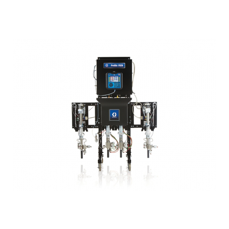
Graco ProMix PD2K Repair Parts
Proportioner for automatic spray applications
Hide thumbs
Also See for ProMix PD2K:
- Operation (180 pages) ,
- Repair parts (82 pages) ,
- Installation manual (62 pages)
Table of Contents
Advertisement
Quick Links
Repair-Parts
ProMix® PD2K Proportioner for
Automatic Spray Applications
Electronic positive displacement proportioner for fast-setting two-component materials. System for
automatic dispense, with Advanced Display Modules. For professional use only.
Important Safety Instructions
Read all warnings and instructions in this manual and in your
installation, operation, and associated component manuals. Save
these instructions.
See page 3 for model part numbers and
approvals information.
PROVEN QUALITY. LEADING TECHNOLOGY.
332709D
EN
Advertisement
Table of Contents
Troubleshooting

Related Manuals for Graco ProMix PD2K


Summary of Contents for Graco ProMix PD2K
- Page 1 Repair-Parts ProMix® PD2K Proportioner for Automatic Spray Applications 332709D Electronic positive displacement proportioner for fast-setting two-component materials. System for automatic dispense, with Advanced Display Modules. For professional use only. Important Safety Instructions Read all warnings and instructions in this manual and in your installation, operation, and associated component manuals.
-
Page 2: Table Of Contents
Contents Models............... 3 Dual Panel Models (AC1002, AC2002) ... 40 Optional Cables and Modules ....... 46 Related Manuals ..........6 Communications Options (for PLC and Warnings ............7 AWI) ........47 Important Isocyanate (ISO) Information ....10 Repair..............48 Material Self-ignition........10 Before Servicing .......... -
Page 3: Models
Warning: Substitution of components may impair intrinsic safety. PART NO. SERIES SERIAL MAX FLUID WPR 2.068 20.68 MFG. YR. GRACO INC. P.O. Box 1441 Minneapolis, MN MAX TEMP 50°C (122°F) 55440 U.S.A. Figure 1 Model AC1000 and AC1002 (Low Pressure) Identification Label ®... - Page 4 PART NO. SERIES SERIAL MAX FLUID WPR 10.34 103.4 1500 MFG. YR. GRACO INC. P.O. Box 1441 Minneapolis, MN MAX TEMP 50°C (122°F) 55440 U.S.A. Figure 3 Model AC2000 and AC2002 (High Pressure) Identification Label ®...
- Page 5 Models Figure 7 Pump Expansion Kit (Accessory) Identification Label 332709D...
-
Page 6: Related Manuals
Related Manuals Related Manuals Current manuals are available at www.graco.com. Manual No. Description Manual No. Description 333282 Remote Mix Manifold Instructions-Parts Manual 332458 PD2K Proportioner Installation 332456 Pump Expansion Kits Manual, Automatic Systems Instructions-Parts Manual 332564 PD2K Proportioner Operation 334183... -
Page 7: Warnings
Warnings Warnings The following warnings are for the setup, use, grounding, maintenance and repair of this equipment. The exclamation point symbol alerts you to a general warning and the hazard symbol refers to procedure-specific risks. When these symbols appear in the body of this manual or on warning labels, refer back to these Warnings. Product-specific hazard symbols and warnings not covered in this section may appear throughout the body of this manual where applicable. - Page 8 Warnings WARNING INTRINSIC SAFETY Intrinsically safe equipment that is installed improperly or connected to non-intrinsically safe equipment will create a hazardous condition and can cause fire, explosion, or electric shock. Follow local regulations and the following safety requirements. • Be sure your installation complies with national, state, and local codes for the installation of electrical apparatus in a Class I, Group D, Division 1 (North America) or Class I, Zones 1 and 2 (Europe) Hazardous Location, including all of the local safety fire codes (for example, NFPA 33, NEC 500 and 516, OSHA 1910.107, etc.).
- Page 9 Warnings WARNING PERSONAL PROTECTIVE EQUIPMENT Wear appropriate protective equipment when in the work area to help prevent serious injury, including eye injury, hearing loss, inhalation of toxic fumes, and burns. This protective equipment includes but is not limited to: • Protective eyewear, and hearing protection. •...
-
Page 10: Important Isocyanate (Iso) Information
Important Isocyanate (ISO) Information Important Isocyanate (ISO) Information Material Self-ignition Isocyanates (ISO) are catalysts used in two component materials. Isocyanate Conditions Some materials may become self-igniting if applied too thick. Read material manufacturer’s warnings and Safety Data Sheet (SDS). Spraying or dispensing fluids that contain Keep Components A and B Separate isocyanates creates potentially harmful mists, vapors, and atomized particulates... - Page 11 Important Isocyanate (ISO) Information Moisture Sensitivity of Isocyanates NOTE: The amount of film formation and rate of crystallization varies depending on the blend of ISO, the humidity, and the temperature. Exposure to moisture (such as humidity) will cause ISO to partially cure; forming small, hard, abrasive crystals, which become suspended in the fluid.
-
Page 12: Important Acid Catalyst Information
Important Acid Catalyst Information Important Acid Catalyst Information Only the PD2K Acid Catalyst Model Proportioners are designed for acid catalysts (“acid”) currently used in two-component, wood-finishing materials. Current acids in use (with pH levels as low as 1) are more corrosive than earlier acids. - Page 13 Important Acid Catalyst Information Moisture Sensitivity of Acid Catalysts NOTICE Acid build-up will damage the valve seals and Acid catalysts can be sensitive to atmospheric reduce the performance and life of the catalyst moisture and other contaminants. It is recommended pump.
-
Page 14: Troubleshooting
Troubleshooting Troubleshooting NOTE: Check all possible remedies before disassembling the system. System Troubleshooting Problem Cause Solution Unit will not operate. Inadequate power supply. Technical Data, page Turn switch on. Power switch is off. Main power is shut off. Turn main power switch on. Exhausted fluid supply. -
Page 15: Error Code Troubleshooting
Troubleshooting Error Code Troubleshooting System errors alert you of a problem and help NOTE: A Record saves relevant system events in the prevent off-ratio spraying. There are three types: background. These are informational only and can Advisory, Deviation, and Alarm. be reviewed on the Events screen, which displays the 200 most recent events, with date, time, and NOTE: Dual Panel systems (AC0502, AC1002... - Page 16 Troubleshooting Purge Errors Code Type Description Problem Cause Solution ETD1 Devia- Autodump System has completed Potlife time has expired No action required. tion Color (A) an auto dump of the and the system was not Passed contents from the pump purged, so the system all the way out to the gun.
- Page 17 Troubleshooting Mix Errors Code Type Description Problem Cause Solution F7S1 Alarm Flow The solvent flow switch Solvent flow switch is Clean or replace switch. Detected is indicating unexpected stuck in flow position. Solvent Gun solvent flow. There is a leak through Check for leaks and the solvent cutoff valve.
- Page 18 Troubleshooting Pumping Errors NOTE: In some error codes listed below, a # symbol is shown as the last digit. This symbol represents the applicable component number, which can vary. The unit’s display will show the applicable number as the last digit in the code.
- Page 19 Troubleshooting Type Description Problem Code Cause Solution DKD# Alarm Position Pump was unable to Not enough air is Ensure that at least 85 Failed reach it’s drive position. supplied to the dosing PSI is being supplied to Pump # valves. the dosing valves.
- Page 20 Troubleshooting Type Description Problem Code Cause Solution F1F# Alarm Flow Low Fill There has been no flow There is a restriction on Make sure there are no Pump # or low flow during a pump the outlet side of the restrictions in the color pump or color stack.
- Page 21 Troubleshooting Pressure Errors NOTE: In some error codes listed below, a # symbol is shown as the last digit. This symbol represents the applicable component number, which can vary. The unit’s display will show the applicable number as the last digit in the code.
- Page 22 Troubleshooting Type Description Problem Code Cause Solution P9D# Alarm Press. Sens. Outlet pressure Outlet pressure Relieve system pressure. Failed Outlet transducer has failed. transducer has failed Verify connections, or replace if reconnecting or the pressure is above the readable range. does not eliminate the alarm.
- Page 23 Troubleshooting System Errors Code Type Description Problem Cause Solution EB00 Rec- Stop Button Record of a stop button Indicates system stop Pressed press. key on ADM was pressed. EBIX Rec- Pumps Record of a pump power Indicates pump power Off Button off button press.
- Page 24 Troubleshooting Communication Errors NOTE: In some error codes listed below, a # symbol is shown as the last digit. This symbol represents the applicable component number, which can vary. The unit’s display will show the applicable number as the last digit in the code.
- Page 25 Troubleshooting USB Errors Code Type Description Problem Cause Solution EAUX Advisory USB Busy USB drive is inserted, Indicates USB port Wait for USB Idle. download is in is uploading or progress. downloading data. EBUX Record USB Drive USB drive was Downloading/upload- Replace the USB Removed...
- Page 26 Lifetime started over at zero. WX00 Alarm Software An unexpected Call Graco technical Errors software error has support. occurred. Calibration Errors NOTE: In some error codes listed below, a # symbol is shown as the last digit. This symbol represents the applicable component number, which can vary.
- Page 27 Troubleshooting Maintenance Errors NOTE: In some error codes listed below, a # symbol is shown as the last digit. This symbol represents the applicable component number, which can vary. For example, the MAD# code listed in this table will be displayed as MAD1 if the affected component is pump 1, MAD2 for pump 2, and so on.
-
Page 28: Power Barrier Board Diagnostics
Troubleshooting Power Barrier Board Diagnostics Figure 8 Power Barrier Board Table 1 . Power Barrier Board Diagnostics Component or Indicator Function LED (green) IS Power LED (green) Power Fuse, 400 mA, 250 V If either F3 or F4 is blown, there is no power to the IS location. -
Page 29: Isolation Board Diagnostics
Troubleshooting Isolation Board Diagnostics Figure 9 Isolation Board Table 2 . Isolation Board Diagnostics Function Component or Indicator LED (yellow) IS Communication LED (green) IS Power LED (green) Non-IS Power LED (yellow) Non-IS Communication Connector Non-IS, Gateway Connector Non-IS, Optional Color Change Module Connector Intrinsically Safe, Barrier Board Connector... -
Page 30: Enhanced Fluid Control Module (Efcm)
Troubleshooting Enhanced Fluid Control Module (EFCM) Diagnostics Figure 10 Enhanced Fluid Control Module Table 3 . Enhanced Fluid Control Module Diagnostics Component or Indicator Function 25 pin connector Pump 1 Module 25 pin connector Pump 2 Module 25 pin connector Pump 3 Module (accessory) 25 pin connector Pump 4 Module (accessory) -
Page 31: Pump Module Diagnostics
Troubleshooting Pump Module Diagnostics Figure 11 Pump Module Table 4 . Pump Module Diagnostics Component or Indicator Function 25 pin connector Input from EFCM 5 pin connector Pump connection 5 pin connector Motor encoder connection 5 pin connector Pump Inlet Transducer 5 pin connector Pump Outlet Transducer 4 pin connector... -
Page 32: Advanced Display Module Diagnostics
Troubleshooting Advanced Display Module Diagnostics Figure 12 Advanced Display Module Table 5 . Advanced Display Module Diagnostics Component or Indicator Function LED (yellow/green) Green: USB inserted Yellow: USB communication LED (red/yellow/green) Green: Power Yellow: Communication Red: Error 8 pin connector Token port 8 pin connector USB port... -
Page 33: Notes
Notes Notes 332709D... -
Page 34: Electrical Schematics
Electrical Schematics Electrical Schematics Standard Models (AC1000, AC2000) NOTE: The electrical schematic illustrates all possible wiring expansions in a ProMix PD2K system; models AC1000 and AC2000. Some components shown are not included with all systems. NOTE: See Optional Cables and Modules, page 46 a list of cable options. - Page 35 Electrical Schematics CONTINUED ON PAGE 3 CONTINUED ON PAGE 3 UNUSED UNUSED UNUSED CABLE (121227) CABLE CABLE GCA MODULE (121227) (121001) GATEWAY 16T072 INTEGRATION (24R910) GATEWAY 1 2 3 4 5 1 2 3 4 5 EFCM CAN IS BOARD (NON IS) (IS) (24M485)
- Page 36 Electrical Schematics GUN TRIGGER INPUTS GCA MODULE GFB PRESSURE SWITCH (121323) SOLVENT FLOW SWITCH 1 (120278) EFCM FLOW RATE ANALOG IN 1 FLOW RATE ANALOG COMMON 1 FLOW RATE ANALOG IN 2 FLOW RATE ANALOG COMMON 2 (24N913) FLOW RATE ANALOG IN 3 FLOW RATE ANALOG COMMON 3 FLOW RATE ANALOG IN 4 FLOW RATE ANALOG COMMON 4...
- Page 37 Electrical Schematics FROM CAN IS BOARD (24M485) CABLE (15V206) 1 2 3 4 5 COLOR CHANGE MODULE 1 MANIFOLD MANIFOLD (COLORS +24VDC FLUSH DUMP 1 THRU 8) +24VDC +24VDC COLOR 1 COLOR 1 +24VDC +24VDC COLOR 2 COLOR 2 +24VDC +24VDC COLOR 3 COLOR 3...
- Page 38 Electrical Schematics CATALYST CHANGE MODULE 6 MANIFOLD MANIFOLD (CATALYST +24VDC 3 THRU 4) DUMP FLUSH +24VDC +24VDC CATALYST 3 CATALYST 3 +24VDC +24VDC CATALYST 4 CATALYST 4 +24VDC UNUSED UNUSED UNUSED UNUSED UNUSED UNUSED UNUSED UNUSED UNUSED UNUSED UNUSED UNUSED UNUSED UNUSED UNUSED...
- Page 39 Electrical Schematics FROM CAN IS BOARD (24M485) NON-HAZARDOUS LOCATION HAZARDOUS LOCATION 1 2 3 4 5 COLOR CHANGE MODULE 7 MANIFOLD MANIFOLD (COLORS +12VDC COLOR FLUSH CATALYST FLUSH 33 THRU 40) +12VDC +12VDC COLOR 1 CATALYST 1 +12VDC COLOR 2 +12VDC CATALYST 2 +12VDC...
-
Page 40: Dual Panel Models (Ac1002, Ac2002)
Electrical Schematics Dual Panel Models (AC1002, AC2002) NOTE:The electrical schematic illustrates all possible wiring expansions in a ProMix PD2K system; models AC1002 and AC2002. Some components shown are not included with all systems. NOTE: See Optional Cables and Modules, page 46 a list of cable options. - Page 41 Electrical Schematics UNUSED UNUSED UNUSED CABLE (121227) CABLE CABLE (121227) (121001) GCA MODULE GATEWAY 16T072 INTEGRATION (24R910) GATEWAY 1 2 3 4 5 1 2 3 4 5 CAN IS BOARD EFCM (NON IS) (IS) (24M485) 1 2 3 4 5 1 2 3 4 5 (24N913) +24VDC...
- Page 42 Electrical Schematics AIR FLOW SWITCH 1 BLACK WHITE AIR FLOW SWITCH 2 GREEN SOLVENT FLOW SW. 1 (120278) LEFT BRKT SOLVENT FLOW SW. 2 (120278) LEFT BRKT SOLVENT FLOW SW. 3 (120278) RIGHT BRKT GCA MODULE AIR CONTROL MODULE (26A231) SOLVENT FLOW SW.
- Page 43 Electrical Schematics FROM CAN IS BOARD (24M485) CABLE (15V206) 1 2 3 4 5 COLOR CHANGE MODULE 1 MANIFOLD MANIFOLD (COLORS +24VDC FLUSH DUMP 1 THRU 8) +24VDC +24VDC COLOR 1 COLOR 1 +24VDC +24VDC COLOR 2 COLOR 2 +24VDC +24VDC COLOR 3 COLOR 3...
- Page 44 Electrical Schematics FROM CAN IS BOARD (24M485) CABLE (16V429) NON-HAZARDOUS LOCATION HAZARDOUS LOCATION 1 2 3 4 5 COLOR CHANGE MODULE 7 MANIFOLD MANIFOLD (COLORS +12VDC BLACK CATALYST FLUSH COLOR FLUSH 33 THRU 40) +12VDC BLACK BLACK +12VDC CATALYST 1 COLOR 1 BLACK +12VDC...
- Page 45 Electrical Schematics CATALYST CHANGE MODULE 6 MANIFOLD MANIFOLD (CATALYST +24VDC 3 THRU 4) DUMP FLUSH +24VDC +24VDC CATALYST 3 CATALYST 3 +24VDC +24VDC CATALYST 4 CATALYST 4 +24VDC UNUSED UNUSED UNUSED UNUSED UNUSED UNUSED UNUSED UNUSED UNUSED UNUSED UNUSED UNUSED UNUSED UNUSED UNUSED...
-
Page 46: Optional Cables And Modules
Electrical Schematics Optional Cables and Modules NOTE: The total length of all cable used in the system must not exceed 150 ft (45 m). See the Electrical Schematics, page M12 CAN Cables, for Hazardous Locations 25 Pin D-SUB Cables, for Non-Hazardous Locations Only NOTE: The total length of cable used in the 16T659... -
Page 47: Communications Options
Electrical Schematics Communications Options (for PLC 2. If your application requires AWI: and AWI) a. 24W829, CGM Kit for PD2K b. 24W462, Modbus TCP* 1. If your application requires integration with a c. 15V337, AWI Module PLC: NOTE: AWI is not currently available for Dual a. -
Page 48: Repair
Repair Repair Before Servicing 1. Flush the system as explained in your PD2K Operation Manual if service time may exceed pot life time. Follow the Pressure Relief Procedure, page 49 before servicing fluid components. 2. Close the main air shutoff valve on the air supply line. -
Page 49: Pressure Relief Procedure
Repair Pressure Relief Procedure With Color Change Follow the Pressure Relief Procedure NOTE: The following procedure relieves all fluid and whenever you see this symbol. air pressure in the system. 1. Turn off the supply pumps. Open the drain valve on the supply line fluid filter to relieve pressure in the supply lines. -
Page 50: Repairing The Advanced Display Module
Repair Repairing the Advanced Display Module (ADM) Replace the ADM 5. Turn the power switch back on. The red indicator light (L) will flash until the new firmware is completely loaded. To replace the Advanced Display Module, disconnect the cable from the module and remove the module 6. -
Page 51: Servicing The Control Box
Repair Servicing the Control Box 8. Turn on the control box power switch. Check that the two green LEDs (D7, D8) and two yellow LEDs (D6, D14) are on. See Figure 24. 9. Reinstall the cover (117) and tighten the screws (124). - Page 52 Repair Replacing the Barrier Board 10. Turn on the control box power switch. Check that the system is operating. NOTICE NOTE: The two green LEDs (D4, D5) on the barrier board will light if the board has power. To avoid damaging the circuit boards when servicing the control box, wear Part No.
- Page 53 2. Remove the fuse (F3 or F4) from its fuseholder. 2. Loosen the screws (124) and remove the enclosure cover (117, not shown). 3. Snap the new fuse (Graco PN 15D979) into the fuseholder. 3. Note the position of the EFCM input and output cables.
- Page 54 Repair Replacing the 24 VDC Power Supply NOTICE 8. Turn on power at the main circuit breaker. 9. Turn on the control box power switch. To avoid damaging the circuit boards when servicing the control box, wear Part No. 112190 NOTE: The green LED on the barrier board (106), grounding strap on your wrist and ground the green power LED on the EFCM module (139),...
- Page 55 Repair Replacing the 48 VDC Pump Power Supply NOTICE 8. Turn on power at the main circuit breaker. 9. Turn on the control box power switch. Press To avoid damaging the circuit boards when servicing the control box, wear Part No. 112190 to turn pump power on.
- Page 56 Repair Replacing a Pump Control Module NOTICE 9. Reinstall the cover (117) and tighten the screws (124). To avoid damaging the circuit boards when servicing the control box, wear Part No. 112190 grounding strap on your wrist and ground appropriately. To avoid electrical component damage, remove all system power before plugging any connectors.
- Page 57 Repair Replacing a Communication Gateway Module NOTICE To avoid damaging the circuit boards when servicing the control box, wear Part No. 112190 grounding strap on your wrist and ground appropriately. To avoid electrical component damage, remove all system power before plugging any connectors. 1.
- Page 58 Repair Replacing the Line Filter NOTICE To avoid damaging the circuit boards when servicing the control box, wear Part No. 112190 grounding strap on your wrist and ground appropriately. To avoid electrical component damage, remove all system power before plugging any connectors. 1.
- Page 59 Repair Replacing the Power Switch NOTICE 7. Reinstall the cover (117) and tighten the screws (124). To avoid damaging the circuit boards when 8. Turn on power at the main circuit breaker. servicing the control box, wear Part No. 112190 grounding strap on your wrist and ground appropriately.
-
Page 60: Servicing The Fluid Section
Repair Servicing the Fluid Section Removing a Pump 7. Loosen the jam nuts holding the pump to the mounting bracket (4). Remove the pump. 8. See manual 332339 to repair the pump. Installing a Pump 1. Slide the pump into the mounting bracket (4). Tighten the jam nuts to secure. - Page 61 Repair Replacing a Solenoid NOTICE To avoid damaging the circuit boards when servicing the control box, wear Part No. 112190 grounding strap on your wrist and ground appropriately. To avoid electrical component damage, remove all system power before plugging any connectors. 1.
- Page 62 Repair Replacing a Fan 7. Connect the 2 fan wires to the pump control module. Use terminal 8, pins 3 and 4. See Electrical Schematics, page NOTICE To avoid damaging the circuit boards when servicing the control box, wear Part No. 112190 grounding strap on your wrist and ground appropriately.
- Page 63 Repair Replacing a Solvent Flow Switch Table 6 Dual Panel Systems Solvent Flow Switches 1. Follow the steps in Before Servicing, page Solvent Flow Switch 1: EFCM Connector J6 Mix Unit #1 Pins 5–6 2. Remove the screws (56) holding the cover (8) to the front of the unit.
-
Page 64: Parts
Parts Parts Proportioner Parts (Standard Models) Part No. AC1000 Low Pressure Proportioner Part No. AC2000 High Pressure Proportioner 332709D... - Page 65 Parts Part No. AC1000 Low Pressure Proportioner Part No. AC2000 High Pressure Proportioner Part Description Part Description — — — — — — FRAME SCREW, machine, pan head; M5 x 0.8; — — — CONTROL BOX, 10 mm electrical; see 24U602 MODULE, display, Control Box Parts,...
- Page 66 Parts Part Description Part Description — — — WASHER; 3/8 223547 GROUND WIRE — — — — — — SCREW, cap, hex SCREW, cap, socket head; 3/8–16 x 2.75 head; 1/4–20 x 3/4 in. in. (70 mm) (19 mm) — — — —...
-
Page 67: Proportioner Parts
Parts Proportioner Parts (Dual Panel Models) Part No. AC1002 Low Pressure Proportioner Part No. AC2002 High Pressure Proportioner 332709D... -
Page 68: Models)
Parts Part No. AC1002 Low Pressure Proportioner Part No. AC2002 High Pressure Proportioner Part Description Part Description — — — FRAME 277853 BRACKET, mounting — — — CONTROL BOX, — — — SCREW, machine, electrical; see pan head; M5 x Control Box 0.8;... - Page 69 Parts Part Description Part Description — — — — — — WASHER; 3/8 TUBE, nylon, red; for control air to — — — SCREW, cap, hex turn valves off; head; 3/8–16 x 5/32 in. (4 mm) OD 2.75 in. (70 mm) x 20 ft (cut to length —...
-
Page 70: Control Box Parts
Parts Control Box Parts Electrical Control Box 332709D... - Page 71 Parts Electrical Control Box (continued) Part Description Part Description — — — — — — ENCLOSURE BRACKET, board — — — PANEL, back 24M485 BOARD, isolation, IS 24T769 POWER SUPPLY; 48 16U725 SWITCH, selector, 2 Vdc; 10 A; 480 W position —...
- Page 72 Parts Part Description Part Description — — — CONNECTOR, bar, 144▲ 172953 LABEL, ground symbol ground — — — CLAMP; for 3/8 in. (10 — — — SCREW, ground; M5 x mm) OD cable 147▲ 15W598 LABEL, warning — — — NUT, hex, flange head;...
-
Page 73: Control Box Parts (Dual Panel Models)
Parts Control Box Parts (Dual Panel Models) Electrical Control Box 332709D... - Page 74 Parts Electrical Control Box (continued) Part Description Part Description — — — — — — LABEL, identification ENCLOSURE — — — — — — GROMMET PANEL, back 16V429 CABLE, CAN, I.S.; 24T769 POWER SUPPLY; fbe; 50 ft. 15.25 m) 48 Vdc; 10 A; 480 W —...
- Page 75 Parts Part Description Part Description — — — 16T660 POWER SUPPLY; SCREW, cap, socket 24 Vdc, 4 A, 96 W head; 8–32 x 0.625 — — — CONNECTOR, bar, in. (16 mm) — — — ground SCREW, machine, — — — SCREW, ground;...
-
Page 76: Solenoid Manifold Parts
Parts Solenoid Manifold Parts Part Description Part No. 24T772 Solenoid Manifold — — — PLATE — — — MANIFOLD — — — SCREW, cap, socket head; 1/4–20 x 0.375 in. (10 mm) 115671 CONNECTOR; 1/8 npt(m) x 1/4 in. (6 mm) OD tube 16P812 VALVE, solenoid... -
Page 77: Technical Data
Technical Data Technical Data Positive Displacement U.S. Metric Proportioner Maximum fluid working pressure: AC0500 and AC0502 300 psi 2.1 MPa, 21 bar Systems with Low-Pressure Pumps 1500 psi 10.5 MPa, 105 bar AC0500 and AC0502 Systems with High-Pressure Pumps AC1000 and AC1002 Air 300 psi 2.1 MPa, 21 bar Spray Systems... - Page 78 Graco to be defective. This warranty applies only when the equipment is installed, operated and maintained in accordance with Graco’s written recommendations. This warranty does not cover, and Graco shall not be liable for general wear and tear, or any malfunction, damage or wear caused by faulty installation, misapplication, abrasion, corrosion, inadequate or improper maintenance, negligence, accident, tampering, or substitution of non-Graco component parts.