Sign In
Upload
Manuals
Brands
Omron Manuals
Robotics
eCobra 600
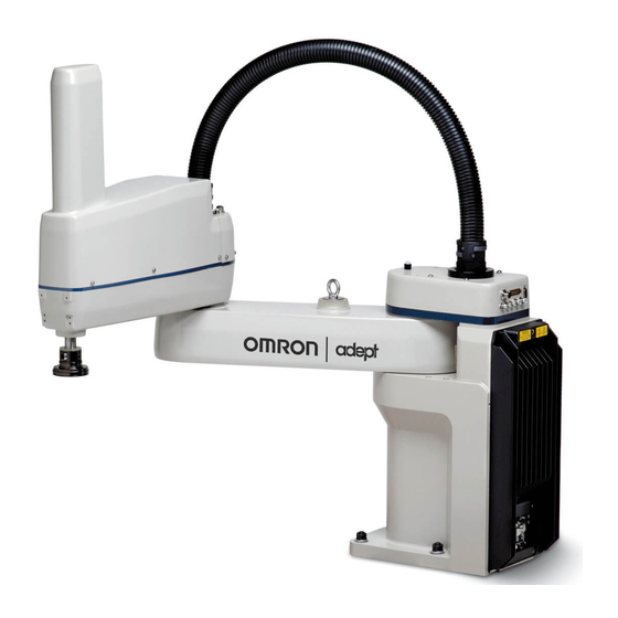
Omron eCobra 600 Manuals
Manuals and User Guides for Omron eCobra 600. We have
2
Omron eCobra 600 manuals available for free PDF download: User Manual
Omron eCobra 600 User Manual (194 pages)
Brand:
Omron
| Category:
Robotics
| Size: 5 MB
Table of Contents
Table of Contents
3
Chapter 1: Introduction
11
Product Description
11
Ecobra Robot Models
12
Eaib (Amplifiers in Base)
13
Ecobra Robot Features and Options
14
Smartcontroller EX
15
Eplc Connect Software
15
IO Blox
15
Smartvision MX
15
T20 Pendant
15
Intelligent Force Sensing
15
ACE Packxpert Process Manager
15
How Can I Get Help
16
Related Manuals
16
Chapter 2: Safety
17
Dangers, Warnings, and Cautions
17
Alert Levels
17
Alert Icons
17
Falling Hazards
17
Special Information
18
What to Do in an Emergency/Abnormal Situation
18
Releasing the Brakes
18
Releasing an E-Stop
18
Emergency Stop Circuit and Buttons
19
General Hazards
19
Safety Precautions
19
User's Responsibilities
19
Qualification of Personnel
20
Robot Behavior
21
Hardstops
21
Limiting Devices
21
Singularities
21
Intended and Non-Intended Use
21
Intended Use
21
Non-Intended Use
22
Robot Modifications
22
Additional Safety Information
22
Manufacturer's Declaration of Incorporation
22
Robot Safety Guide
23
T20 Manual Control Pendant (Option)
23
Disposal
23
Chapter 3: Robot Installation
25
Installation Overview
25
Transport and Storage
25
Unpacking and Inspecting the Equipment
26
Before Unpacking
26
Upon Unpacking
26
Repacking for Relocation
26
Environmental and Facility Requirements
27
Mounting an Upright Ecobra Robot
27
Mounting Surface
28
Mounting Procedure
29
Mounting an Ecobra 800 Inverted Robot
30
Mounting Surface
30
Mounting Procedure
30
Mounting the Front Panel
32
Connectors on Robot Interface Panel (Eaib)
33
Chapter 4: System Installation
35
System Cables, Without Smartcontroller EX
35
List of Cables and Parts
36
Cable Installation Overview
38
System Cables, with Smartcontroller EX
40
Installing a Smartcontroller EX Motion Controller
41
List of Cables and Parts
41
Cable Installation Overview
43
Optional Cables
44
XIO Breakout Cable
44
DB9 Splitter Cable
44
Eaib XBELT IO Adapter Cable
44
Smartcontroller EX Belt Encoder Y-Adapter Cable
44
ACE Software
49
User-Supplied PC
49
Installing ACE Software
49
Connecting 24 VDC Power to Robot
50
Specifications for 24 VDC Power
50
VDC Mating Connector
51
Creating 24 VDC Cable
52
Connecting 24 VDC Cable
52
Connecting 200-240 VAC Power to Robot
54
Specifications for AC Power
54
AC Mating Connector
58
Creating the 200-240 VAC Cable
58
Connecting AC Power Cable
59
Grounding the Robot System
59
Grounding the Robot Base
59
Grounding Robot-Mounted Equipment
60
Configuring a PLC
60
Installing User-Supplied Safety Equipment
62
Emergency Stop Circuits
68
Remote Manual Mode
70
User Manual/Auto Indication
70
User High Power on Indication
70
Remote High Power On/Off Control
71
High Power On/Off Lamp
71
Remote Front Panel or User-Supplied Control Panel Usage
71
Remote Pendant Usage
72
Chapter 5: System Operation
73
Robot Status LED Description
73
Status Panel Fault Codes
73
Status Panel
74
Brakes
80
Brake Release Button
80
Remote Brake Release Feature
81
Front Panel
81
Connecting Digital I/O to the System
83
Optional I/O Products
83
Default Digital I/O Signal Configuration
84
Eaib XIO Connector Signals
86
XIO Input Signals
87
XIO Output Signals
90
XIO Breakout Cable
93
Starting the System for the First Time
94
Verifying Installation
95
Turning on Power
96
Starting ACE
96
Enabling High Power
97
Verifying E-Stop Functions
97
Verify Robot Motions
97
Learning to Program the Ecobra Robot
97
Chapter 6: Maintenance
99
Field-Replaceable Parts
99
Periodic Maintenance Schedule
99
Warning Labels
100
Rev. F Ecobra User's Guide
101
Checking Safety Systems
103
Checking Robot Mounting Bolts
103
Checking for Oil Leakage
103
Lubricating Joint
104
Replacing the Eaib Chassis
107
Removing the Eaib Chassis
107
Installing a New Eaib Chassis
109
Commissioning a System with an Eaib
110
Safety Commissioning Utilities
110
E-Stop Configuration Utility
112
E-Stop Verification Utility
113
Teach Restrict Configuration Utility
113
Teach Restrict Verification Utility
114
Replacing a Microsd Card
115
Removing a Microsd Card from an Eaib
115
Installing a Microsd Card into an Eaib
117
Replacing the Encoder Battery Pack
117
Battery Replacement Time Periods
118
Battery Replacement Procedure
118
Changing the Lamp in the Front Panel High-Power Indicator
119
Chapter 7: Optional Equipment Installation
123
Installing End-Effectors
123
Removing and Installing the Tool Flange
123
Removing the Flange
123
Installing the Flange
124
User Connections on the Robot
125
User Air Lines
125
User Electrical Lines
126
Internal User Connectors
126
SOLND Connector
127
OP3/4 Connector
128
EOAPWR Connector
129
Internal User Connector Output Specifications
129
ESTOP Connector
130
Mounting Locations for External Equipment
132
Installing the Robot Solenoid Kit
132
Tools Required
133
Signal Setup
133
Installation
134
Testing
139
Installing the Camera Bracket Kit
140
Tools Required
140
Procedure
141
Installing Adjustable Hardstops
142
Joint 1 Adjustable Hardstops
142
Joint 2 Adjustable Hardstops
146
Chapter 8: Technical Specifications
153
Dimension Drawings
153
Robot Specifications
166
Physical
166
Performance
167
Stopping Distances and Times
167
Key to Graphs
168
Hardstops and Softstops
174
Chapter 9: IP65 Option
175
Ecobra 800 Robots IP65 Classification
175
Installing Cable Seal Assembly
176
Cable Seal Identification
176
Installation Procedure
176
Robot Outer Link Cover Removal and Reinstallation
178
Cover Removal Procedure
178
Cover Reinstallation Procedure
180
Customer Requirements
181
Sealing the Tool Flange
181
Pressurizing the Robot
182
User Connectors
183
User Electrical and Devicenet
183
User Air Lines
184
Robot Solenoid Option
184
Maintenance
185
IP65 Bellows Replacement
185
Dimension Drawing for Cable Seal Assembly
186
Chapter 10: Cleanroom Robots
189
Cleanroom Specifications
189
Connections
190
Requirements
190
Exclusions and Incompatibilities
191
Cleanroom Maintenance
191
Bellows Replacement
191
Lubrication
192
Advertisement
Omron eCobra 600 User Manual (179 pages)
With EtherCAT
Brand:
Omron
| Category:
Robotics
| Size: 6 MB
Table of Contents
Table of Contents
3
Chapter 1: Introduction
9
Related Manuals
9
Intended Audience
10
Robot Overview
12
Robot Amplifier and Controller
13
IP65 and Cleanroom Versions
16
Robot Features
16
Robot Links and Joints
17
Robot Connections
17
Ics-ECAT Robot Interface Panel
24
Robot Options
25
Solenoid Valve Kit
25
End of Arm Break-Away Sensor
26
IO Blox
27
Optional I/O Items
27
T20 Pendant
28
IPC Application Controller
28
Front Panel
29
Camera Bracket Kit
31
Adjustable Hardstops
32
Optional Cables
33
Chapter 2: Safety
37
Dangers, Warnings, and Cautions
37
Alert Levels
37
Alert Icons
37
Special Information
38
Safety Precautions
38
What to Do in an Emergency
39
Stopping the Robot
39
Fire Response
39
Entrapment and Brake Release Button
39
Robot Behavior
39
Hardstops
39
Limiting Devices
39
Singularities
39
Intended Use of the Robot
40
Additional Safety Information
40
Manufacturer's Declarations
40
Robot Safety Guide
40
T20 Pendant (Option)
40
Disposal
41
How Can I Get Help
41
Chapter 3: Robot Installation
43
Robot Installation Overview
43
Basic Installation Steps
43
Mounting an Ecobra Robot
43
Mounting Surface
44
Mounting Procedure
44
Install the Tool Flange
46
Tool Flange Installation Procedure
47
Installing the Front Panel
47
Connecting the Front Panel
47
Front Panel Schematic
48
Installing User-Supplied Safety Equipment
49
Contacts on XUSR Connector
49
Contacts on XFP Connector
51
Remote Pendant Signals on the XMCP Connector
51
E-Stop Circuits on XUSR and XFP Connectors
53
Emergency Stop Circuits
54
Remote Manual Mode
56
User Manual/Auto Indication
56
Remote High Power on / off Control
56
Using a User-Supplied Control Panel
57
Remote Pendant Usage
58
Setting the Ethercat Node ID
58
Setting the Ethercat Node ID Using Hardware Switches
59
Chapter 4: System Cable Installation
61
Basic System Cable Layout
61
List of Cables and Parts
62
Cable Installation Steps
64
XBELT IO Belt Encoder y Adapter Cable
65
Connecting Digital I/O to the System
67
Digital I/O Signal Configuration
68
XIO Connector Signals
76
Connecting the 24 VDC Cable to the Robot
78
VDC Power Supply Connector
78
Making the 24 VDC Power Supply Cable
79
Connecting the 24 VDC Cable
79
Connecting 200-240 VAC Power Cable
81
AC Power Diagrams
81
AC Power Supply Connector
83
Making the 200-240 VAC Power Supply Cable
83
Connecting the AC Power Supply Cable
84
Grounding the Robot System
84
Grounding the Robot Base
85
Grounding Robot-Mounted Equipment
85
Chapter 5: Optional Equipment Installation
87
Installing End-Effectors
87
Mounting Locations for External Equipment
88
Installing the Solenoid Valve Kit
89
Solenoid Valve Kit Installation Procedure
90
Testing Solenoid Valve Kit Installation
93
Installing the Camera Bracket Kit
93
Tools Required
93
Procedure
93
Installing Adjustable Hardstops
95
Joint 1 Adjustable Hardstop Installation
95
Joint 2 Adjustable Hardstop Installation
96
Chapter 6: System Operation
99
Verifying Installation
99
Mechanical Checks
99
System Cable Checks
99
User-Supplied Safety Equipment Checks
100
Switch Position Checks
101
Robot Status LED and Display Panel
101
General Robot States
101
Ethercat Communications Description
102
System Behavior with Ethercat Communication Errors
103
Brakes
103
Brake Release Button
103
Remote Brake Release Feature
104
Robot Control Modes
104
Manual Mode
104
Automatic Mode
105
Operation Mode
105
Service Mode
105
Manually Jogging the Robot
106
Enabling Robot High Power
106
High Power Safety Timeout
106
High Power and Faults
107
High Power Request Methods
107
Disabling Robot High Power
108
Chapter 7: Maintenance
111
Periodic Maintenance
111
Periodic Maintenance Schedule
111
Checking Safety Systems
111
Checking Robot Mounting Bolts and Cover Plates
112
Checking Safety and Warning Labels
112
Checking for Oil Leaks
114
Lubricating Joint 3
115
Replacing the Encoder Battery Pack
117
Non-Periodic Maintenance
119
Field-Replaceable Parts
120
Remove the Tool Flange
120
Replacing the Ics-ECAT Amplifier Chassis
121
Remove and Replace a Microsd Card
125
Change Front Panel High-Power on Lamp
126
Chapter 8: Technical Specifications
131
Robot Physical Dimension Drawings
131
General Robot Specifications
136
Performance Specifications
137
General Performance Information
137
Stopping Distances and Times
138
Hardstop and Softstop Limits
144
Electrical Specifications
145
Internal Connection Specifications
145
External Connection Specifications
145
Environment and Facility Specifications
147
Other Specifications
148
Solenoid Valve Kit Specifications
148
Connector Specifications
148
Power Consumption Specifications
149
Tool Flange Dimensions
149
Front Panel Dimensions
150
Ethercat Communications Specifications
151
Chapter 9: IP65 Option Considerations
153
IP65 Option Classification
153
User Requirements to Meet IP65 Rating
153
Sealing the Tool Flange
154
Pressurizing the Robot
154
Cable Seal Assembly
156
Cable Seal Identification
156
Dimension Drawing for Cable Seal Assembly
158
Remove and Reinstall Outer Link Cover
159
Outer Link Cover Removal Procedure
159
Outer Link Cover Reinstallation Procedure
160
IP65 Robot Connections
162
Joint 1 Connections
162
Pneumatic Pass-Through Connections
163
Robot Solenoid Option Consideration for IP65 Robots
163
IP65 Option Maintenance
164
IP65 Bellows Replacement
164
Chapter 10: Cleanroom Option Considerations
167
Cleanroom Option Classification
167
User Requirements to Meet Cleanroom Rating
167
Cleanroom Robot Connections
168
Robot Solenoid Option Consideration for Cleanroom Robots
168
Cleanroom Option Maintenance
169
Cleanroom Bellows Replacement
169
Advertisement
Related Products
Omron Quattro 650H
Omron Quattro 650HS
Omron eCobra 800
Omron eCobra 800 Inverted Robots
Omron INTELLI 637IT
Omron 61F-G
Omron 61F-G3
Omron 61F-G4L 2KM
Omron 61F-11H
Omron 61F-GL4KM
Omron Categories
Blood Pressure Monitor
Controller
Accessories
Switch
Inverter
More Omron Manuals
Login
Sign In
OR
Sign in with Facebook
Sign in with Google
Upload manual
Upload from disk
Upload from URL