Sign In
Upload
Manuals
Brands
Oki Manuals
Printer
Teriostar LP-1040 Series
Oki Teriostar LP-1040 Series Manuals
Manuals and User Guides for Oki Teriostar LP-1040 Series. We have
4
Oki Teriostar LP-1040 Series manuals available for free PDF download: Maintenance Manual, User Manual, Installation Manual, Quick Reference Manual
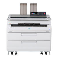
Oki Teriostar LP-1040 Series Maintenance Manual (746 pages)
Wide Format Multifunction Printer
Brand:
Oki
| Category:
Printer
| Size: 40.08 MB
Table of Contents
Table of Contents
9
Figure 1.1 Maintenance Work Flow
27
Maintenance Work Process Overview
27
Required Tools
28
Table 1-1 Required Tools List
28
Figure 1.2 Part Names and Functions (Front Side/Right Side)
29
Front Side/Right Side
29
Part Names and Functions
29
Figure 1.3 Part Names and Functions (Rear Side/Left Side)
30
Rear Side/Left Side
30
Figure 1.4 Part Names and Functions (Inside)
31
Inside
31
Figure 1.5 Part Names and Functions (Operation Panel)
32
Operation Panel
32
Figure 1.6 Installation/Maintenance Space
33
Installation/Maintenance Space
33
Compaticle Hardware
34
Upgrading System Firmware
35
System Firmware Format
36
Product Key
37
About the USB Drive for Upgrade
39
Upgrading Using the USB Drive (from the Operation Panel)
40
Upgrading from a Web Browser
42
Upgrading Using USB Memory (at Startup)
43
Errors When Upgrading
45
Table 1-2 List of Upgrade Errors
45
Replacing the ARC Board
46
Replacing with a New ARC Board
46
Replacing with a Used ARC Board
47
Checks after Firmware Upgrade and Board Replacement
48
How to Acquire Information When a Problem Occurs
49
Chapter 2 Engine Maintenance Mode
50
How to Enter Maintenance Mode
51
Figure 2.1 Password Input Screen
51
Maintenance Diagnostic Items Overview and How to Use Them
52
Maintenance Diagnostic Items
52
Table 2-1 Maintenance Diagnostic Items
52
How to Use the Maintenance Diagnostics
53
Table 2-2 Correspondence between Roll Papers and Paper Widths
54
Maintenance Diagnostic Items
56
Cumulative Print Length
56
Table 2-3 Cumulative Print Length Items
56
Table 2-4 A3 and A4 Counter's Count-Up Values on A1 and A3
57
Table 2-5 A3 and A4 Counter's Count-Up Values on A2 and A0
58
Unrecoverable Error Log
59
Table 2-6 Elements of Unrecoverable Error Codes
59
Table 2-7 Example of an Unrecoverable Error Log
59
Table 2-8 Unrecoverable Error Codes and Their Details
60
Table 2-9 Information and Its Contents on the Type of Paper Used When an Error Occurred
61
Jam Error Log
62
Table 2-10 Elements of Paper Jam Error
62
Table 2-11 Paper Jam Log Example
62
Table 2-12 Paper Jam Error Codes and Their Details
63
Process Cartridge Log
64
Table 2-13 Process Cartridge Log Example
64
Part Replacement Data
65
Table 2-14 Elements of Part Replacement Data
65
Table 2-15 Part Replacement Data Details
65
Part Cleaning Data
66
Table 2-16 Elements of Part Cleaning Data
66
Table 2-17 Parts for Cleaning and Cleaning Cycle
66
Thermistor
68
Table 2-18 Thermistors and Halogen Heaters: Status and Meaning
68
Sensor
69
Table 2-19 Elements of Sensor Data
69
Table 2-20 Sensor Status Messages
69
Actuator
71
Table 2-21 Elements of Actuator Data
71
Table 2-22 Actuator Status Message List
71
Test
73
Table 2-23 Test Items
73
Nip Pressure Adjustment
74
Table 2-24 Nip Pressure Calibration Parameters
74
Print
75
Table 2-25 Executable Items Overview under the Print Menu
75
Table 2-26 Executable Items under the Print Menu (Details)
75
Positioning
77
Table 2-27 Positioning Functions
77
Table 2-28 Executable Items under the Top Edge Alignment Menu (1)
78
Table 2-29 Executable Items under the Top Edge Alignment Menu (2)
78
Table 2-30 Executable Items under the Top Edge Alignment Menu (3)
78
Table 2-34 Executable Items under the Print Length Adjustment Menu (1)
81
Parameter
87
Table 2-43 Engine Control Parameters (200-299)
87
Table 2-44 Engine Control Parameters (600-699)
89
Table 2-45 Engine Control Parameters (700-799)
91
Table 2-46 Engine Control Parameters (800-899)
93
Potentiometer
96
Table 2-47 Engine Control Parameter Numbers
96
Messages
97
Technician Menu Functions
98
Table 2-48 Items Initialized through HDD Format
99
Table 2-49 Return to Default Settings
102
How to Enter the Web Based Maintenance Mode
107
Chapter 3 Regular Service Inspections
109
Regular Service Inspection Work Items and Their Details
110
Table 3-1 Regular Service Inspection Items
110
Table 3-2 Regular Inspection Items (Multifunction Model Only)
112
Table 3-3 Regular Inspection Items (Multifunction Model Only)
113
Cleaning Methods
114
Cleaner Blade
114
Charge Wire
115
Transfer Roller
116
How to Apply Grease
117
Charger Unit High Voltage Contact
117
Photoconductor Drum Ground Contact
118
Heat Roller Contact
119
Chapter 4 Controller Problems Troubleshooting
121
Troubleshooting - Basic Workflow
122
Error Messages
123
Table 4-1 Error Category
124
Error Log
125
Message List
126
Controller Error Messages
126
Table 4-2 Troubleshooting for Controller-Related Service Call Errors
126
Table 4-3 Troubleshooting for Controller-Related Warnings
140
Table 4-4 Troubleshooting for Problems Related to Door, Toner, Cover, and Paper
154
Controller Problem Diagnosis
156
The Product Key Is Required Error
160
The Product Key Is Not Correct, or the ARC Board's EEPROM Has Not Been Replaced Error
161
The Product Key Is Not Correct, or the ASC Board's EEPROM Has Not Been Replaced Error
162
EEPROM Is Corrupted Error
163
The Printer will Operate for 720 Hour(S) Only Is Displayed on the Ready Screen
164
The MAC Address Has Not Been Assigned Error
165
Unable to Upgrade Scanner Firmware Error
167
Error Log Reference
168
Table 4-5 Jam Error
168
Table 4-6 Door Open
169
Table 4-7 Toner
169
Table 4-8 Waste Toner Bottle
169
Table 4-9 Process Cartridge
169
Table 4-10 Folder
169
Setup Data Is Incorrect Error
170
Low Ambient Temperature Warning
171
Specific Operation
172
How to Use Specific Operation
173
Chapter 5 Engine Problems Troubleshooting
175
Table 5-1 Troubleshooting for Engine Problems
176
Troubleshooting Overview
183
Level 1 Problem Analysis
184
Level 2 Problem Analysis
185
Unrecoverable Error Code Problem Analysis
185
Paper Jam Error Code Problem Analysis
195
Table 5-2 Troubleshooting on Paper Jam Error
195
Problem Analysis Based on Symptoms
214
Chapter 6 Scanner Troubleshooting
222
Table 6-1 Troubleshooting on Scanner Problem
223
How to Read the Information Presented in this Chapter
227
Scanner Troubleshooting Outline
227
Level 1 Problem Analysis
227
Level 2 Problem Analysis
227
Error Solutions
228
Problem Analysis Based on Symptoms
228
Chapter 7 Printer Image Quality Problems Troubleshooting
230
How to Troubleshoot Image Quality Problems
230
Types of Engine Test Patterns
231
Table 7-1 Engine Test Pattern
231
Troubleshooting Print Specification Problems
233
Print Specifications and How to Measure Them
233
Print Specification Problem Solutions
235
Troubleshooting Image Quality Problems
236
Table 7-2 Image Quality Problem Troubleshooting Item List
236
How to Visually Check LED Head Lighting
279
Chapter 8 Scanner Image Quality Problems Troubleshooting
281
Image Misalignment (Top)
282
Image Misalignment (Center)
283
Vertical Lines (Black or White)
284
Density Irregularities
285
Other Problems
286
Chapter 9 Parts Disassembly, Assembly, and Replacement
288
How to Read the Information Presented in this Chapter
288
Reading the Assembly/Disassembly Instructions
288
Removing External Parts
289
Maintenance Parts Table
306
Cover-Unit
306
Waste Toner Bottle Unit
306
Cutter-Unit
306
Developer Unit
306
Drive-Unit
307
Electrical Unit
307
Fuser Base Unit
307
Fuser Unit
308
Main Frame Unit
308
Operation Panel Unit
309
Process Cartridge Unit
309
Roll Feed Unit Low 1040
309
Scanner Unit
310
Sub Frame Unit
310
Transfer Roller Unit
310
Transport Unit
310
Jigs
311
Cover-Unit
312
Push Latch Mnt
312
Document-Table-Low Mnt
313
Waste Toner Bottle Unit
316
Ts02] Waste Toner Sensor,Ts02 Mnt
316
Ms05] Micro Switch,04,05,06-1 Mnt
318
Cutter-Unit
319
Cutter Unit Auto Mnt
319
Developer Unit
322
Developer Unit Mnt
322
Ts01] Toner Sensor,Ts01 Mnt
325
Gm01] Motor Gm Mnt
326
Ms04] Micro Switch,04,05,06-1 Mnt
327
Magnet Roll Mnt, Spacer Dev Mnt
328
Blade-S-DV Mnt
330
Drive-Unit
332
Clutch 4.4 Mnt
332
Pm01] Motor Pm01 Mnt
337
Electrical Unit
339
Recommended Parts for the ELECTRICAL UNIT
339
Aac] Pcb-Assy-Aac1 Mnt
341
[Arc] Pcb-Assy-Arc1 Mnt/Pcb-Assy-Arc2 Mnt, [Eeprom] T2Arc-Eeprom Mnt
342
Hdd Mnt
345
Bl05-02] Blower Fan Assy Mnt
346
Sw01] [Sw02] Main Switch 120V 200V Mnt
347
Ac Inlet Mnt
349
Pcb-Assy-Asc Mnt
350
Ps] Psu-T2 Mnt
352
Bl05-01][Bl05-03][Bl05-04] Bl05 Assy Mnt
357
Hv-Ps] Hv(4Ch)-Psu-T2 Mnt
359
Fuser Base Unit
365
Bl06] Blower Fan,Bl01,02,06 Mnt
365
Fuser Unit
366
Fuser Unit Low,Without Heater,Mnt
366
Bl-02] Blower Fan,Bl01,02,06 Mnt
379
Sl01 Low Mnt
380
Hm01] Motor Hm Mnt
382
Spur Fuser Mnt
384
FL01][FL02] Halogen Heater
385
Torque Limiter Mnt
389
TH01][TH02][TH04] THERMISTOR and TH01,02,04,05 MNT
393
Fuse Assy Mnt
399
MS06-1]MICRO SWITCH,04,05,06-1 MNT and [MS06-2]MICRO SWITCH,06-2 MNT
400
Peeler Fu out Mnt
403
Separator (BUR) MNT
404
Roller Heat Mnt
407
Roller Back up St Mnt
412
Sheet Carbon Br Mnt
413
Ps07] Photosensor,04,05,07 Mnt
414
Fus Gear Mnt
415
Main Frame Unit
418
Major Recommended Parts Locations for MAIN FRAME UNIT
418
Th06][Hu01] Temperature Humidity Sensor Mnt
419
Tm01] Motor Tm Assy Mnt
420
Int3][Ms18] Interlock Switch,Int3,Ms18 Mnt
422
Ps04][Ps05] Photosensor,04,05,07 Mnt
424
Ps16] Photointerrupter,Ps16 Mnt
426
Bl03] Bl03 Assy Mnt
427
Heater Roll Paper Mnt
428
Torque Limitter Regist Mnt
429
Operation Panel Unit
434
Panel Assy Mnt, Panel Assy Pl Mnt
434
Process Cartridge Unit
436
Scorotron Charger Unit
436
Drum Finger W Mnt
437
Wire(Charger)Mnt
440
Eraser Assy Mnt
442
Blade-Cleaner-Ss002 Mnt
444
Filter T2 Mnt, Filter Fus Mnt
448
Main Recommended Parts Arrangement on the ROLL FEED UNIT LOW 1040
449
Gear Limitter Mnt
450
Ps1X][Ps2X][Ps5X] PHOTOINTERRUPTER MNT
451
Roller Rewind Mnt
454
Gear Oneway Mnt
456
Fm0X] MOTOR FM MNT
458
Pt0X] PTM ASSY MNT
459
SCANNER UNIT (Multifunction Model Only)
464
Glass Document Mnt
464
Pss01To 08] REFLECTIVE PHOTOSENSOR MNT (CIS Unit Front Side) and
469
[PSS09] PHOTOINTERRUPTER MNT (Cover Open/Close Sensor)
469
PSS11] REFLECTIVE PHOTOSENSOR MNT (Behind CIS Unit)
471
Roller Sc G Assy Mnt
475
Roller Pinch Kk Mnt
479
CIS UNIT MNT and PCB-ASSY-AIC1 MNT
490
Motor Sc Mnt
496
Plate Shading Assy Mnt
498
Sub Frame Unit
501
Led Head Mnt
501
Pcb-Assy-Acn1 Mnt
503
TRANSFER ROLLER UNIT (Transfer/Detack Corotron)
504
Removing the TRANSFER ROLLER UNIT
504
Guide DC R Mnt, Guide DC L Mnt, Detach Needle
507
GEAR TRA ONEWAY MNT and SPACER TRA MNT
511
ROLLER TRA 3565 MNT and SHEET TRA MNT
513
Spacer Transfer Guide Mnt
517
Transport Unit
518
Transport Unit Mnt
518
Bl01] Blower Fan,Bl01,02,06 Mnt
519
Ps06] Photosensor,06 Mnt
520
Belt Trans Mnt
521
Jigs
522
Cotton Ciegal Mnt
522
Cleaner
523
Opc Cleaner
526
Adjuster Kit(Scanner)
528
Adjustment Kit(Color Scanner)
529
Copy/Scan Color Chart1 Set
529
Contact Grease Mnt
530
Heatproof Grease Mnt
530
Toolkit Mnt
531
Air Blow Tool
531
Gear-Spacer Mnt
531
Push-Pull Gauge
532
Chapter 10 Printer Calibration
533
High Voltage Power Supply Voltage/Current Calibration
533
Primary Charger Load Current Calibration
534
Developer AC Bias
538
Developer DC Bias
540
Separator AC Bias
542
Checking the Transfer Unit Voltage
544
Measuring the Low Voltage Power Supply Voltage
546
Table 10-1 List of Print Specification Problem Calibration Items
548
Fuser Unit's Nip Pressure Calibration
549
Skew/Slack Calibration
552
Cut Squareness Calibration
557
Cut Length Accuracy Calibration
559
Print Length Accuracy Calibration
562
Top Edge Alignment Calibration
566
Center Alignment Calibration
570
Lead Edge Dead Space Adjustment
574
LED Head Connection Calibration
575
LED Focal Point Calibration
584
LED Head Light-Emitting Strobe Width Calibration
587
Table 10-2 LED Head Light-Emitting Strobe Width and Density Change Calibration Value
587
Adjusting Paper Outlet Shutter Solenoid (SL01)
588
TRANSPORT UNIT Adjustment
591
Fuser Unit Temperature Adjustment
593
Installing the SPACER CUTTER Used for Adjusting the Cutter Unit Position
596
Chapter 11 Scanner Calibration
599
Calibration (Monochrome Scanner)
599
Equipments Needed for Calibration
599
Figure 11.1 Equipment Needed for Calibration
599
Calibration Tasks Overview
600
PC for Calibration
601
Calibration/Evaluation Document
603
Preparing for Calibration
605
Shading Offset Calibration Instructions
608
Position Adjustment Instructions
635
Checking Adjustment Results
639
Scanner Adjustment Results - Memo List
645
How to Change the Scanner Parameters
646
Scanner Parameters Lists
647
Verification (Color Scanner)
675
Items Required for Verification
675
Verification Task Overview
675
Computer for Verification Details
676
Verification Originals
677
Color Difference Verification Procedure
678
CIS Connection Verification Procedure
684
Chapter 12 Printer Operation Guide
688
Features
689
Engine Specifications Outline
690
Paper Flow and Part Names
692
Figure 12.1 Paper Flow and Part Names
692
Basic Overall Operation
693
Basic Layout Block Diagram
693
Figure 12.2 Basic Layout Block Diagram
693
Figure 12.3 Outline of Printer Components
694
Table 12-1 Sensors and Actuators
695
Circuitry Layout Block Diagram
697
Figure 12.4 Circuitry Layout Block Diagram
697
Operation Overview
698
Electrophotographic Process Operation
700
Primary Charger
700
Photoconductor Drum
701
Exposure
702
Developer
703
Transfer Unit
704
Separator
705
Cleaning
705
Discharge Unit
706
Fuser Unit
706
Drive/Transport Systems Operation
708
Drive System
708
Paper Transport System
708
Control System
710
Process Control
710
Paper Feed Control
710
Controller Unit
711
Controller Specification Outline
711
Hardware Configuration
712
Figure 12.5 Controller Block Diagram (ARC Block)
712
Chapter 13 Scanner Operation Guide
713
Features
713
Scanner Specifications Outline
713
Table 13-1 Scanner Specifications
713
Table 13-2 Copy Function Overview
714
Table 13-3 Scanner Submission Function Overview
714
Basic Operations
715
Basic Layout Block Diagram
715
Figure 13.1 Basic Layout Block Diagram (Scanner Unit)
715
Outline of Printer Configuration
716
Figure 13.2 Scanner Side View
716
Figure 13.3 Scanner Top View
716
Circuitry Layout Block Diagram
718
Figure 13.4 Circuitry Layout Block Diagram (Scanner Unit)
718
Operation Overview
719
Scanner Controller Unit (ASC1 Board)
721
Hardware Configuration (ASC1 Board)
721
Figure 13.5 Scanner Controller Block Diagram
721
CIS Unit (AIC1 Board and CIS)
722
Hardware Configuration (AIC1 Board and CIS)
722
Figure 13.6 CIS Unit Block Diagram
723
Advertisement
Oki Teriostar LP-1040 Series User Manual (290 pages)
Wide Format Printer
Brand:
Oki
| Category:
Printer
| Size: 15.76 MB
Table of Contents
Section 1
15
Safety Precautions
4
Warning Labels
8
Manual Structure
10
Reading the Manual
10
D-SCAN Format
11
Notations
11
Supplied Items at Printer Installation
12
Consumables
13
Options
13
Table of Contents
15
Chapter before Use
23
Features
24
Operation Requirements
26
Environment Requirements
26
Ensure Good Ventilation
27
Installation/Maintenance Space
28
Supported Paper
29
Part Names and Functions
32
Front Side
32
Left Side and Rear Side
33
Inside
34
Operation Panel
35
Mode Screen
39
Section 2
41
Turning the Power On/Off
42
Powering on
43
Chapter 2 Describes the Basic Operations for the Printer. These Include Turning the
43
T Turning the Power On/Off
43
Powering off
45
Replacing the Roll Paper
46
Replacement Precautions
47
T Replacing the Roll Paper
47
Removing the Roll Paper
48
Installing the Roll Paper
49
Replacing the Toner Cartridge
52
Handling Precautions
53
T Replacing the Toner Cartridge
53
Toner Replacement Procedure
54
Replacing the Waste Toner Bottle
57
Replacement Precautions
58
Waste Toner Bottle Replacement Procedure
58
Replacing the Charger Unit
61
Charger Unit Replacement Procedure
61
Replacing the Process Cartridge
65
Replacement Precautions
65
Process Cartridge Replacement Procedure
66
T Replacing the Process Cartridge
66
Job Operation
72
Handling Print Jobs
73
Printing Pause and Cancellation
73
T Job Operation
73
Web Functions
74
Functions
74
Starting the Web Functions
75
T Web Functions
75
Cleaning the Exterior
76
Using Paper from a New Size Standard
77
Using Paper from a User Defined Series
79
Restricting the Available Rolls
81
Menu Mode Screen
84
Confirming Printer Restart
86
Paper Menu
87
Rolls 1 and 2 Paper Types
87
Rolls 1 and 2 Standards
87
Printer Engine Menu
89
Power Save Time
89
Top Cut Timer for Roll N (N = 1 to 2)
89
Top Cut at Door Open
90
Humidity for Tracing Paper
91
Power Saving in Standby
91
Print Density
91
Output Report to Tray
92
Print Reports with Other Paper
92
Communication Parameters
93
T System Menu
94
Available Size Standards
104
Paper Size Standards
105
User Defined Size
106
Printer Settings
107
Ports Settings Menu
113
Common Settings
113
Port 1 to 10
114
Setup Items in PDL Settings Menu
117
Available Data Formats
117
Automatic Data Format Identification
117
Setting Parameter Table in PDL Setting Menu
118
PDL Parameter Priority Mode
119
Paper Parameters
120
Drawing Parameters
126
Scale Parameters
129
Format Parameters (Only with HP-GL and D-SCAN)
136
Pen Parameters (Only with HP-GL and D-SCAN)
142
Raster Parameters
146
PDC (Print Data Converter) Parameters
147
Stamp Parameters
150
Function Menu
153
Print System Settings
153
Print Print Settings
153
Print Copy Settings MF
153
Print Submission Settings MF
153
Print All Settings
154
Print for Fax Transmission
154
Print Error Log
154
Print Engine Information
154
Print Scanner Information MF
154
Initialize Port Accounting Information
154
Print Port Accounting Information
155
Initialize for Std Use
155
All Output Trays to on
155
All Output Trays to off
155
PDL Setting Print (Port 1 to 10)
155
Options Settings Menu
156
Submission Destination Setting Menu
157
Adjustment Menu
161
Smart Card Settings Menu
162
Import/Export Menu
163
Export Operation
167
Import Operation
168
Date and Time Settings Menu
169
Delete HDD Data Menu
170
Print Job Box Function/T T T T
171
Print Job Box Function
171
T T T T
171
Overview of the Print Job Box Function
172
Print Job Box Settings Menu
173
Print Job Box Operation
175
Preparation
178
Smart Card Registration Procedure
178
Using Smart Cards with the Print Job Box Function
178
Authentication Function
185
Authentication Function Overview
186
Chapter 4 Describe the Authentication Func Tion for the Printer
186
T Printer Administration
190
T User Authentication
199
T Smart Card Registration Procedure
224
Troubleshooting
225
Initial Checks
226
When the Error Screen Appears
227
Error Log Reference
237
T Ethernet Troubleshooting
249
Image Quality Defects
250
Unusual Sound
251
When You Have Set the Wrong Language
252
Oki Teriostar LP-1040 Series Installation Manual (91 pages)
Wide Format Printer
Brand:
Oki
| Category:
Printer
| Size: 5.35 MB
Table of Contents
Table of Contents
8
Installation Procedure Overview
11
Procedure and Required Personnel
11
Tools
12
Printer Appearance and Part Names
13
Chapter 2 Site Preparation Check
15
Installation Environment
15
Installation Surface
17
Installation Space
18
Electrical Configuration
19
Receive the Shipment and Set up the Printer in the Final Position
21
Move to the Unpacking Location
22
Select the Unpacking Location
22
Move the Printer
23
Unpack
24
Unpacking Procedure
24
Unpacking Post-Check
28
Move to the Final Position
29
Hardware Installation
30
Locate the Printer
30
Adjusting Leveling Feet
31
Remove any Shock Absorption Materials and Stabilizers
32
Remove the Panel Protective Sheet
35
Release the LED Head and Developer Unit
36
Attach the Transfer/Detach Corotron
38
Attach the Process Cartridge
40
Attach the Electrical Box Access Cover
40
Attach the Document Table (Multifunction Printer Model Only)
41
Attach the Original Output Guide (Multifunction Printer Model Only)
46
Connect the Power Cord
46
Power on the Printer / Supply the Toner
47
Chapter 4 Prepare the Printer
50
Confirm the Printer Operation Without Connecting to a Computer
53
Chapter 6 Connecting the Interface Cables
54
Configuration
55
Interface Cables
56
Connection Method
57
Chapter 7 Confirm System-Wide Operation and Complete the Hardware Installation
58
Confirm System-Wide Operation
59
Ensure the Printer's Installation Conditions
60
Chapter 8 Handover
61
Using this Chapter
61
Turning the Power on and off
62
Mode Buttons
63
Replace Paper
64
Supply Toner
68
Replace the Waste Toner Bottle
71
Replace the Process Cartridge
74
Remove Paper Jams
80
Copy
82
Scan
83
Web Operations
86
Appendix A List of Functions
87
Functions
87
Appendix B Factory Default Settings
88
Factory Default Settings
88
Appendix C Frequently Asked Questions (FAQ
89
Advertisement
Oki Teriostar LP-1040 Series Quick Reference Manual (32 pages)
Wide Format Printer
Brand:
Oki
| Category:
Printer
| Size: 3.72 MB
Table of Contents
Table of Contents
2
Turning the Power On/Off
3
Power on
3
Power off
3
Mode Buttons
3
Replacing the Paper
4
Replacing the Toner Cartridge
6
Replacing the Waste Toner Bottle
8
Replacing the Charger Unit
10
Replacing the Process Cartridge
12
Part Names
14
Paper Jams
16
Copying
22
Importing Images (Documents) to a Computer
23
Operating the Printer from a Computer
25
Troubleshooting
26
When an Error Message Appears
26
Smears on a Printout
26
Changing the Time until Power Save Mode
26
Automatic Paper Cutting after a Certain Time
26
Automatic Paper Cutting after Opening
27
And Closing a Door
27
Changing the Print Density
27
Wrinkles on Tracing Paper
27
Selecting Paper to Match the Print Data
27
Missing Print or Slow Data Reception
28
Service Representatives
31
Disposal Method
31
Advertisement
Related Products
Oki Teriostar LP-1030
Oki Teriostar LP-1040-MF
Oki LP441s
Oki LP470w
Oki LP441b
Oki LP-2050
Oki LP480
Oki LP440
Oki LP441
Oki LP-2060-MF
Oki Categories
Printer
All in One Printer
Printer Accessories
Fax Machine
Label Maker
More Oki Manuals
Login
Sign In
OR
Sign in with Facebook
Sign in with Google
Upload manual
Upload from disk
Upload from URL