Oki LP-1040 Maintenance Manual
Wide format multifunction printer
Hide thumbs
Also See for LP-1040:
- User manual (290 pages) ,
- Quick reference manual (32 pages) ,
- Installation manual (91 pages)

Related Manuals for Oki LP-1040


Summary of Contents for Oki LP-1040
- Page 1 LP-1040/LP-1040-MF Wide Format Multifunction Printer Maintenance Manual U10000140900...
- Page 2 U10000140900 August, 2016 Initial Publication Copyright© 2016 OKI Data Infotech Corporation. All rights reserved. The contents of this manual may be changed without prior notice. Ethernet is a registered trademark of the Xerox Corporation (USA). HP-GL is a registered trademark of the Hewlett-Packard Company (USA).
- Page 3 The illustrations and control panel figures used in this manual are taken from one of the printers if it does not differ from the method of operation and does not hinder maintenance work. The LP-1040 printer model may not be sold in some countries or regions. Note ...
- Page 4 Safety Notices In this manual, the following symbols are used to alert the reader to information that will prevent damage/malfunction of the Printer, and to ensure safe and correct inspection/maintenance procedures are carried out. Ensure that you thoroughly understand each of these symbols and follow the information written by each carefully.
- Page 5 Warning Be very careful not to touch the transfer/detack corotron labeled HIGH VOLTAGE inside the Printer. There is a risk of electrical shock. Be very careful not to touch the fuser unit labeled HIGH TEMPERATURE inside the Printer. Burn injuries may result. Do not disassemble the Printer any further than is instructed in this manual.
- Page 6 Warning Labels Warning labels are affixed to the Printer in the locations shown in the figure below. Make sure you understand the information on the warning labels before inspecting/repairing the Printer. High temperature warning label A High temperature warning label A Instruction label to remove paper jams High temperature warning label B High temperature warning label B...
- Page 7 High temperature warning label This label warns against touching heated parts. The fuser unit can become very hot. Be careful not to touch this area when removing a paper jam or performing any other work in this area. Instruction label to remove paper jams This label indicates the removal direction for jammed paper when a jam occurs in the fuser unit.
- Page 8 Cautionary Notes When Performing Maintenance Work When performing inspection/maintenance work, always be aware of the following items. (1) Begin your inspection/maintenance work only after confirming with the user the current status of the Printer and the state of the Printer when the trouble occurred. In some cases there may not be any problem with the Printer itself, but instead it may be a problem resulting from the use of non-standard toner/paper or a data problem, so always check the status of the printer first.
-
Page 9: Table Of Contents
Table of Contents Table of Contents Chapter 1 Maintenance Work Process Overview Maintenance Work Process Overview ..................1-1 Required Tools ..........................1-2 Part Names and Functions ......................1-3 1.3.1 Front Side/Right Side ....................... 1-3 1.3.2 Rear Side/Left Side ........................1-4 1.3.3 Inside............................ - Page 10 Maintenance Diagnostic Items...................... 2-7 2.3.1 Cumulative Print Length......................2-7 2.3.2 Unrecoverable Error Log ....................... 2-10 2.3.3 Jam error log .......................... 2-13 2.3.4 Process Cartridge Log ......................2-15 2.3.5 Part Replacement Data ......................2-16 2.3.6 Part Cleaning Data ......................... 2-17 2.3.7 Thermistor ..........................
- Page 11 Table of Contents 4.4.1 Controller Error Messages ....................... 4-6 4.4.2 Controller Problem Diagnosis ....................4-36 The product key is required error ....................4-40 The product key is not correct, or the ARC board’s EEPROM has not been replaced error..4-41 The product key is not correct, or the ASC board's EEPROM has not been replaced error ..
- Page 12 Chapter 7 Printer Image Quality Problems Troubleshooting How to Troubleshoot Image Quality Problems ................7-1 7.1.1 Types of Engine Test Patterns ....................7-2 Troubleshooting Print Specification Problems ................7-4 7.2.1 Print Specifications and How to Measure Them ..............7-4 7.2.2 Print Specification Problem Solutions ..................
- Page 13 Table of Contents 9.2.15 TRANSFER ROLLER UNIT ....................9-23 9.2.16 TRANSPORT UNIT ....................... 9-23 9.2.17 Jigs ............................9-24 COVER-UNIT ..........................9-25 9.3.1 PUSH LATCH MNT ........................ 9-25 9.3.2 DOCUMENT-TABLE-LOW MNT .................... 9-26 WASTE TONER BOTTLE UNIT ....................9-29 9.4.1 [TS02] WASTE TONER SENSOR,TS02 MNT ..............9-29 9.4.2 [MS05] MICRO SWITCH,04,05,06-1 MNT ................
- Page 14 9.10 FUSER UNIT ..........................9-79 9.10.1 FUSER UNIT LOW,WITHOUT HEATER,MNT ..............9-79 9.10.2 [BL-02] BLOWER FAN,BL01,02,06 MNT ................9-92 9.10.3 SL01 LOW MNT ........................9-93 9.10.4 [HM01] MOTOR HM MNT ...................... 9-95 9.10.5 SPUR FUSER MNT ....................... 9-97 9.10.6 [FL01][FL02] Halogen Heater ....................9-98 9.10.7 TORQUE LIMITER MNT ......................
- Page 15 Table of Contents 9.14 ROLL FEED UNIT LOW 1040 ....................9-162 9.14.1 Main Recommended Parts Arrangement on the ROLL FEED UNIT LOW 1040 ....9-162 9.14.2 GEAR LIMITTER MNT......................9-163 9.14.3 [PS1x][PS2x][PS5x] PHOTOINTERRUPTER MNT ............. 9-164 9.14.4 ROLLER REWIND MNT ...................... 9-167 9.14.5 GEAR ONEWAY MNT ......................
- Page 16 9.19.5 ADJUSTMENT KIT(COLOR SCANNER) ................9-242 9.19.6 Copy/Scan Color Chart1 Set ....................9-242 9.19.7 CONTACT GREASE MNT ....................9-243 9.19.8 HEATPROOF GREASE MNT ....................9-243 9.19.9 TOOLKIT MNT ........................9-244 9.19.10 AIR BLOW TOOL ......................... 9-244 9.19.11 GEAR-SPACER MNT ......................9-244 9.19.12 PUSH-PULL GAUGE ......................
- Page 17 Table of Contents Chapter 11 Scanner Calibration 11-1 11.1 Calibration (Monochrome Scanner) ..................... 11-1 11.1.1 Equipments Needed for Calibration ..................11-1 11.1.2 Calibration Tasks Overview..................... 11-2 11.1.3 PC for Calibration ........................11-3 11.1.4 Calibration/Evaluation Document ................... 11-5 11.1.5 Preparing for Calibration ......................11-7 11.1.6 Shading Offset Calibration Instructions ................
- Page 18 12.5.4 Developer ..........................12-16 12.5.5 Transfer Unit ........................12-17 12.5.6 Separator ..........................12-18 12.5.7 Cleaning ..........................12-18 12.5.8 Discharge Unit ........................12-19 12.5.9 Fuser Unit ..........................12-19 12.6 Drive/Transport Systems Operation ..................12-21 12.6.1 Drive System ........................12-21 12.6.2 Paper Transport System ...................... 12-21 12.7 Control System .........................
- Page 19 Table of Contents Annex A ARC1/ARC2 Board Configuration and Display Annex B AAC1 Board Configuration and Display Annex C ASC1 Board Configuration and Display Annex D AIC1 Board Configuration and Display Annex E Wiring Schematic Annex F Timing Diagram xvii...
- Page 20 Figures Figure 1.1 Maintenance Work Flow ......................1-1 Figure 1.2 Part Names and Functions (Front Side/Right Side) ..............1-3 Figure 1.3 Part Names and Functions (Rear Side/Left Side) ..............1-4 Figure 1.4 Part Names and Functions (Inside) .................... 1-5 Figure 1.5 Part Names and Functions (Operation Panel) ................1-6 Figure 1.6 Installation/Maintenance Space ....................
- Page 21 Table of Contents Tables Table 1-1 Required Tools List ........................1-2 Table 1-2 List of Upgrade Errors ........................ 1-19 Table 2-1 Maintenance Diagnostic Items ..................... 2-3 Table 2-2 Correspondence between roll papers and paper widths .............. 2-5 Table 2-3 Cumulative Print Length Items ..................... 2-7 Table 2-4 A3 and A4 counter's Count-Up Values on A1 and A3 ..............
- Page 22 Table 2-35 Executable Items Under the Print Length Adjustment Menu (2) ..........2-33 Table 2-36 Executable Items Under the Print Length Adjustment Menu (3) ..........2-33 Table 2-37 Executable Items Under the Cut Length Adjustment Menu (1) ..........2-34 Table 2-38 Executable Items Under the Cut Length Adjustment Menu (2) ..........2-35 Table 2-39 Executable Items Under the Cut Length Adjustment Menu (3) ..........
- Page 23 Table of Contents Table 13-4 Scanner Component Parts and Engineering Names ............... 13-5...
- Page 24 Troubleshooting index (Error type) Errors that start with E E AC (2400 to 4004) Accounting task ..........4-6 E AL (4001 to 5013) Authentication log task ........4-6 E BT (1000 to 7FF2) Platform (boot) ........... 4-6 E CI (1100 to 6000) Common file task (SMB/CIFS) ......4-6 E CP (2781 to 27A3) Copy task ............
- Page 25 Table of Contents E SL (0010 to 4002) Data spool library ..........4-16 E SM (4001 to 4007) Serial number mismatch check task ..... 4-16 E SN (8800 to 8803) SNMP ..............4-16 E SP (1101 to E00B) Data spool task ..........4-16 E TM (4000) Timer ................
- Page 26 W SN (8810 to C020) SNMP ............... 4-31 W SP (4101 to C802) Data spool task ..........4-31 W TW (4000 to 83FF) Twain (file task) ..........4-32 Errors that start with O ............. 4-34 Paper Jam Error ..............5-21 ...
-
Page 27: Maintenance Work Process Overview
Chapter 1 Maintenance Work Process Overview This chapter discusses the work instructions, required tools, and the names of parts required for initial maintenance of the Printer. Maintenance Work Process Overview Maintenance work can be divided into two categories: regular inspections based on a maintenance agreement and maintenance required when a malfunction or other problem occurs. -
Page 28: Required Tools
Required Tools The tools and measuring devices required for maintenance work are shown in the table below. Table 1-1 Required Tools List Name Amt. Notes USB memory For system firmware upgrade (USB 2.0) Phillips screwdriver 1 each Magnetic #2 (Shaft length = 100 mm or 3.94 inches, 200 mm or 7.87 inches) Magnetic #3 Stubby screwdriver (Shaft length = 38 mm or 1.50 inches) -
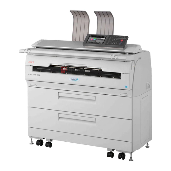
Page 29: Part Names And Functions
Chapter 1 Maintenance Work Process Overview Part Names and Functions The following shows the names of parts and the functions they perform in the Printer. 1.3.1 Front Side/Right Side (1) Operation panel (6) Waste toner door (11) Document table (2) Scanner cover (7) Drawer for roll 2 (12) Original width guide (3) Fuser unit drawer... -
Page 30: Rear Side/Left Side
1.3.2 Rear Side/Left Side (1) Toner door (5) Rear door (2) Heater switch (6) Original output guide (3) Main power switch (7) Top cover (4) Power cord Figure 1.3 Part Names and Functions (Rear Side/Left Side) -
Page 31: Inside
Chapter 1 Maintenance Work Process Overview 1.3.3 Inside (1) Paper flange (2) Paper feed knob (3) Process cartridge drawer (4) Ethernet interface connector Figure 1.4 Part Names and Functions (Inside) -
Page 32: Operation Panel
1.3.4 Operation Panel The names and functions of the primary parts of the operation panel are given below. See the User's Manual for more details. * Items enclosed in dotted lines are on the multifunction model only. Figure 1.5 Part Names and Functions (Operation Panel) (1) Button used to move between different modes The green lamp lights up when the current mode is selected. -
Page 33: Installation/Maintenance Space
Chapter 1 Maintenance Work Process Overview Installation/Maintenance Space Keep enough space around the Printer as shown in the figure below in order to ensure enough ventilation for the Printer and to facilitate easy maintenance work, replacement of expendable parts, and handling of output paper. Figure 1.6 Installation/Maintenance Space... -
Page 34: Compaticle Hardware
Compaticle Hardware The following pieces of hardware are compatible with the LP-1040 model. ●ARC board The ARC board cannot be used in common with the LP-2050/LP-1030 model. Use an ARC board for the LP-2060/LP-1040 model. ●HDD Use an HDD of 500 GB or higher. -
Page 35: Upgrading System Firmware
Chapter 1 Maintenance Work Process Overview Upgrading System Firmware The following firmware applications are included in the supplied firmware package. - Controller firmware - Scanner firmware - Controller unit boot ROM You can use one of the following three methods to upgrade the firmware. Upgrade using a USB drive (from the operation panel) You can upgrade the firmware from the operation panel using a USB drive. -
Page 36: System Firmware Format
Example: t2e_v1.10.zip - t2e: Firmware for the LP-2060/LP-1040 model. - v1.10: Version The supplied firmware is for the LP-2060/LP-1040 model. Decompress the file to obtain the following system files. TS_FW.BIN File used to upgrade the firmware using a USB drive (from the operation panel) or using a Web browser. -
Page 37: Product Key
Chapter 1 Maintenance Work Process Overview 1.6.2 Product Key Since the firmware is used for both LP-2060 and LP-1040 models, a product key of 20 digits (see below) must be set to the Printer to differentiate the printer models. Example: 1206-2EEA-FDE6-2B83-1B57 The product key is a unique number different for each model and each serial number. - Page 38 When such a screen is displayed, enter the correct product key under Enter Product Key in Menu (1/2) -> Menu (2/2) of the operation panel. * The screen above is also displayed if the EEPROM has not been replaced after replacing the ARC board.
-
Page 39: About The Usb Drive For Upgrade
Chapter 1 Maintenance Work Process Overview 1.6.3 About the USB Drive for Upgrade To upgrade the firmware using a USB drive (from the operation panel or during restart), it is necessary to create a USB drive for upgrade. A USB drive for upgrade is a commercially available USB drive to which system files have been saved. -
Page 40: Upgrading Using The Usb Drive (From The Operation Panel)
1.6.4 Upgrading Using the USB Drive (from the operation panel) Follow the instructions below to upgrade the firmware from the operation panel using the USB drive for upgrade. ◇ With the multifunction model, the firmware cannot be upgraded when the Note scanner is jammed with original documents. - Page 41 Chapter 1 Maintenance Work Process Overview Press the OK button to close the window and start the upgrade process. (6) Press the OK button again to confirm. The state of the upgrade process is displayed with a progress bar. The message Upgrade complete.
-
Page 42: Upgrading From A Web Browser
1.6.5 Upgrading from a Web Browser The TS_FW.BIN file is used to upgrade the firmware from a Web browser. * Use the supplied TS_FW.BIN file. Follow the instructions below. ◇ The upgrading process takes 5 or 6 minutes. Never turn the Printer off during Notes the process. -
Page 43: Upgrading Using Usb Memory (At Startup)
Chapter 1 Maintenance Work Process Overview 1.6.6 Upgrading Using USB Memory (at Startup) If the controller firmware is corrupted, due to the Printer being turned off during the upgrade process or other operation, and the Printer cannot start, use the method below to restore the system. - Page 44 <4> When installing Rip-FW FW is running the upgrade. [Rip] Rip-FW upgrade is running. [writing] <5> When completing the upgrade FW is running the upgrade. [Rip] Rip-FW upgrade is running. Please turn off the main power supply. FW upgrade was completed successfully. <6>...
-
Page 45: Errors When Upgrading
Chapter 1 Maintenance Work Process Overview 1.6.7 Errors When Upgrading The following message will be displayed should an error occur during the upgrade process. ERROR: VU-XXXX XXXX: One of the error codes from the table below will be displayed here. Table 1-2 List of Upgrade Errors Error Error Name and/or Error... -
Page 46: Replacing The Arc Board
Replacing the ARC Board Follow one of the procedures below to replace the ARC board. After replacing the ARC board, upgrade the firmware to the latest version. 1.7.1 Replacing with a New ARC Board Follow the procedure below when replacing the ARC board with a new one. (1) Turn the Printer off. -
Page 47: Replacing With A Used Arc Board
Chapter 1 Maintenance Work Process Overview 1.7.2 Replacing with a Used ARC Board Follow the procedure below when replacing the ARC board with board already used. (1) Turn the Printer off. (2) Remove the ARC board from the Printer. (3) Replace the EEPROM on the new ARC board with the EEPROM from the old ARC board. See p.9-55 for the ARC board EEPROM replacement procedure. -
Page 48: Checks After Firmware Upgrade And Board Replacement
Checks After Firmware Upgrade and Board Replacement The following checks must be performed after upgrading the firmware version, replacing the boards or replacing the EEPROM. Execute Menu -> Function -> Print System Settings. Check the following items. (a) Printer information - Product name Check that the product name is correct. -
Page 49: How To Acquire Information When A Problem Occurs
Chapter 1 Maintenance Work Process Overview How to Acquire Information When a Problem Occurs Through Chapters 4 to 8, troubleshooting for each unit is described. However, a problem that cannot be resolved immediately may sometimes arise. In such cases, use one of the two procedures below to acquire information from the printer on which the problem occurred. -
Page 50: Chapter 2 Engine Maintenance Mode
Chapter 2 Engine Maintenance Mode When performing regular inspections or troubleshooting in the event of a problem, you will be using the engine maintenance mode feature discussed in this chapter. To use the engine maintenance mode you will need to input a password and enter maintenance mode. -
Page 51: How To Enter Maintenance Mode
How to Enter Maintenance Mode To use the engine maintenance mode functions, input a login name for technician and a password, and enter maintenance mode * These instructions are the same for both printer and multifunction models. (1) Press the Menu button. The top menu screen will appear. (2) Press the buttons on the operation panel in the following order. -
Page 52: Maintenance Diagnostic Items Overview And How To Use Them
Chapter 3 Regular Service Inspectionse Maintenance Diagnostic Items Overview and How to Use Them 2.2.1 Maintenance Diagnostic Items Table 2-1 Maintenance Diagnostic Items Item Description Cumulative print length Displays the cumulative print length of each roll. Unrecoverable Error Log Displays information about errors that could not be recovered from. Jam error log Displays information about paper jam errors. -
Page 53: How To Use The Maintenance Diagnostics
2.2.2 How to Use the Maintenance Diagnostics Switch to maintenance mode and select the desired maintenance diagnosis item. * Transfer Roller Adjustment is not available with this model. The operation after the selection are classified into four below. Operation Description Display Action Display the current status. -
Page 54: Table 2-2 Correspondence Between Roll Papers And Paper Widths
Chapter 3 Regular Service Inspectionse Clear Clear the cumulative print length related to the maintenance. The information is cleared by clicking the OK button. Change setting Change the current setting's value. There are two methods for this, as shown below. Numerical Input - Select an item to change, and input the value with the number pad. - Page 55 Selection Input - Select an item from the list of items displayed. Select from a list of items. Execute Execute the operation. Or, stop the currently executing operation.
-
Page 56: Maintenance Diagnostic Items
Chapter 3 Regular Service Inspectionse Maintenance Diagnostic Items 2.3.1 Cumulative Print Length Displays the cumulative print length (in either meters or feet) and the A3 and A4 counter value. Table 2-3 Cumulative Print Length Items Item Meaning Operation ← Display Cumulative Print Length [m]/[ft] Display Only ←... -
Page 57: Table 2-4 A3 And A4 Counter's Count-Up Values On A1 And A3
Table 2-4 A3 and A4 counter's Count-Up Values on A1 and A3 Printout length Count-Up Value [mm] [inches] [line] Roll papers identified by the Roll papers identified by the (up to) (up to) (up to) Printer as A3 width, e.g., with the Printer as A1 width, e.g., with the following width: following width:... -
Page 58: Table 2-5 A3 And A4 Counter's Count-Up Values On A2 And A0
Chapter 3 Regular Service Inspectionse Table 2-5 A3 and A4 counter's Count-Up Values on A2 and A0 Printout length Count-Up Value [mm] [inches] [line] Roll paper identified as A2 Roll paper identified as A0 (up to) (up to) (up to) width by the Printer width by the Printer - 420 mm;... -
Page 59: Unrecoverable Error Log
2.3.2 Unrecoverable Error Log Displays information about the latest 21 unrecoverable errors that have occurred, from newest to oldest. A single error consists of the following elements. Table 2-6 Elements of Unrecoverable Error Codes Item Meaning Operation Error Code See Below Display only Information about the type of paper used when See Below... -
Page 60: Table 2-8 Unrecoverable Error Codes And Their Details
Chapter 3 Regular Service Inspectionse (1) Unrecoverable Error Codes and Their Details Table 2-8 Unrecoverable Error Codes and Their Details Error Code Error Details 2010 FMxx (Paper Feed Pulse Motor x) Trouble 2011 - 2013 FM01 (Paper Feed Pulse Motor 1) Trouble 2014 - 2016 FM02 (Paper Feed Pulse Motor 2) Trouble 2017 - 2019... -
Page 61: Table 2-9 Information And Its Contents On The Type Of Paper Used When An Error Occurred
Information about the type of paper used when an error occurred and the contents of that information The meanings of the six characters representing the paper information at the time of an error are shown in the table below. Table 2-9 Information and Its Contents on the type of paper used when an error occurred First and Second Characters Meaning (Roll paper position) -
Page 62: Jam Error Log
Chapter 3 Regular Service Inspectionse 2.3.3 Jam error log Displays information about the latest 21 paper jam errors that have occurred, from newest to oldest. A single paper jam error consists of the following elements. Table 2-10 Elements of Paper Jam Error Item Meaning Operation... -
Page 63: Table 2-12 Paper Jam Error Codes And Their Details
(1) Paper jam error codes and their details Table 2-12 Paper Jam Error Codes and Their Details Error Error Details Code 3400 The paper is jammed at the PS04 sensor, that is, under the cutter. 3401, 3402 The lead edge of the paper is reaching PS04 too quickly. 3403, 3404 The lead edge of the paper is not reaching PS04. -
Page 64: Process Cartridge Log
Chapter 3 Regular Service Inspectionse 2.3.4 Process Cartridge Log Displays information about the cumulative print length of the process cartridge. [0001] 2010-07-09(12:34:56) 123456789m Process Cartridge Log Example [0001] 2010-07-09(12:34:56) 123456789m Table 2-13 Process Cartridge Log Example [0001] Process cartridge number 2010-07-09(12:34:56 PM) The date of last use. -
Page 65: Part Replacement Data
2.3.5 Part Replacement Data Displays as reference data for the part replacement: - The cumulative print length after the part replacement; and - The cumulative print length with which the part replacement is recommended You can also clear the cumulative print length after part replacement to 0. ◇... -
Page 66: Part Cleaning Data
Chapter 3 Regular Service Inspectionse 2.3.6 Part Cleaning Data Displays as reference data for the part cleaning: - The cumulative print length after the part cleaning; and - The cumulative print length with which the part cleaning is recommended You can also clear the cumulative print length after part cleaning to 0. ◇... - Page 67 Cleaning Cycle Part Name Unit: m Unit: ft Roller (REWIND) 10000 m (393700 inches) 32808 ft Bearing (DR-22-H6) Cutter unit (AUTO) 10000 m (393700 inches) 32808 ft 2-18...
-
Page 68: Thermistor
Chapter 3 Regular Service Inspectionse 2.3.7 Thermistor Displays the state of the thermistors and the halogen heater. Table 2-18 Thermistors and Halogen Heaters: Status and Meaning Code Category Status and Meaning TH02 Fuser temperature overheat sensor Normal: No overheating TH02's status Overheat: Overheating TH01 Center fuser temperature sensor TH01's... -
Page 69: Sensor
PS12, PS13, PS14, PS22, PS23, PS40, PS52, PS53, and PS54 are not installed. - LP-1040 (for 2 rolls): PS13, PS14, PS23, PS40, PS53, and PS54 are not installed. To check the status of PS06, fix the sensor with adhesive tape not leaving adhesive when removed. - Page 70 Chapter 3 Regular Service Inspectionse Turning the beep sound On/Off (1) Select the sensor whose status you want to display. (2) The status of the selected sensor will be displayed. (3) If the beep sound is turned On, a beep is output in accordance with changes in sensor status.
-
Page 71: Actuator
Before changing the rotation direction of the motor, temporarily switch off the motor. Do not change the statuses for the actuators below, as they are not installed on the printer. - LP-1040 (for 1 roll): FM02, FM03, FM04 - LP-1040 (for 2 rolls): FM03, FM04 2-22... - Page 72 Chapter 3 Regular Service Inspectionse ALL action specification (1) Turn off all actuators' actions. 2-23...
-
Page 73: Test
2.3.10 Test Executes the test function. Table 2-23 Test Items Item Description Operation CC CHECK Tests the adjustment of the primary charger current. Start DB CHECK Tests the adjustment of the developer bias. Start DC CHECK Tests the adjustment of the separator bias. Start LED-HEAD ON Switches on the lighting of the LED head... -
Page 74: Nip Pressure Adjustment
Chapter 3 Regular Service Inspectionse 2.3.11 Nip Pressure Adjustment Executes a print operation to adjust the fuser nip pressure. Select a test pattern and Paper Postion to execute the print operation. Table 2-24 Nip Pressure Calibration Parameters Selection Item Name Selection Meaning Test Pattern... -
Page 75: Print
2.3.12 Print Prints the test patterns contained in the engine. Specify the pattern to print by selecting one of the following items. Table 2-25 Executable Items Overview Under the Print Menu Item Description Operation Test Pattern See table below. Select Paper Postion Roll x (x: the roll number) Select... - Page 76 Chapter 3 Regular Service Inspectionse Item Name Selection Meaning Test Pattern Grid, with 2-dot width diagonal lines Grid, with 1-dot width and 2-dot width lines Solid black Solid white Vertical stripe, composed of 1-dot width black and 3-dot width white lines Vertical stripe, composed of 2-dot width black and 2-dot width white lines Paper Postion Roll x...
-
Page 77: Positioning
2.3.13 Positioning Executes the positioning functions shown in the table below. Table 2-27 Positioning Functions Function Description Top Edge Alignment Executes a print operation for the top edge alignment. Center Alignment Executes a print operation for the center alignment. Print Length Adjustment Executes a print operation for the print length adjustment. -
Page 78: Table 2-28 Executable Items Under The Top Edge Alignment Menu (1)
Chapter 3 Regular Service Inspectionse Table 2-28 Executable Items Under the Top Edge Alignment Menu (1) Item Name Option Meaning Print Length 2523 mm 2523mm = 99.33 inches = 8413 (59599 lines) 841 mm 841 mm = 33.11 inches (19866 lines) 297 mm 297 mm = 11.69 inches (7016 lines) - Page 79 Center Alignment Executes a print operation for the center alignment. Selecting Paper Position displays the EEPROM and RAM values of the corresponding engine control parameter for the center alignment. Use the number pad to change the RAM value. Click the Save button to save the RAM Value in the EEPROM. ◇...
- Page 80 Chapter 3 Regular Service Inspectionse Table 2-33 Executable Items Under the Center Alignment Menu (3) Recommended Item Name Meaning Input Range* RAM Value 0 - 100 RAM value of engine control parameter for the center alignment. *: Values between 0 and 65535 can be entered. 2-31...
-
Page 81: Table 2-34 Executable Items Under The Print Length Adjustment Menu (1)
Print Length Adjustment Executes a print operation for the print length adjustment. Selecting Print Length or Paper Type displays the EEPROM and RAM values of the corresponding engine control parameter. Use the number pad to change the RAM value. Click the Save button to save the RAM Value in the EEPROM. ◇... - Page 82 Chapter 3 Regular Service Inspectionse Table 2-35 Executable Items Under the Print Length Adjustment Menu (2) Item Name Display Meaning Parameter No. 718 - 723 Number of engine control parameter for the print length adjustment. EEPROM Value 3050 - 3200 EEPROM value of engine control parameter for the print length adjustment.
- Page 83 Cut Length Adjustment Executes a print operation for the cut length adjustment. Selecting Print Length or Paper Type displays the EEPROM and RAM values of the corresponding engine control parameter. Use the number pad to change the RAM value. Click the Save button to save the RAM Value in the EEPROM. ◇...
- Page 84 Chapter 3 Regular Service Inspectionse Table 2-38 Executable Items Under the Cut Length Adjustment Menu (2) Item Name Display Meaning Parameter No. 801 - 848 Number of engine control parameter for the cut length adjustment. EEPROM Value 0 - 1000 EEPROM value of engine control parameter for the cut length adjustment.
- Page 85 Remaining Paper Based Executes a print operation for correcting the cut length based on the remaining paper. <Preparation> Prepare two rolls, one with the maximum remaining length and one with the minimum remaining length, of the paper width and paper type you want to adjust. * They are not necessary if the cut lengths from the roll front and the roll end are already known, and only enter the cut length with the roll front in Length Roll Front, and the cut length with the roll end in Length Roll End.
- Page 86 Chapter 3 Regular Service Inspectionse Table 2-40 Executable Items Under the Remaining Paper Based Menu (1) Item Name Option Meaning Print Length 2523 mm 2523mm = 99.33 inches = 8413 (59599 lines) 1682 mm 1682mm = 66.22 inches = 8412 (39732 lines) 841 mm 841 mm = 33.11 inches...
-
Page 87: Parameter
2.3.14 Parameter Change the RAM value of the engine control parameter. When changing engine control parameter 620, press the In 600s button to switch the page and display engine control parameter 620. Next, if the No.620 RAM value is pressed, a value input popup is displayed. Enter a value. (The input range is from 0 to 65535.) (1) After changing the engine control parameter RAM value to the default, save to the EEPROM value. - Page 88 Chapter 3 Regular Service Inspectionse 2-39...
-
Page 89: Table 2-44 Engine Control Parameters (600-699)
Table 2-44 Engine Control Parameters (600-699) Top Edge Alignment Value Selections for Top Edge Alignment Standard Number Input Range Print Paper Value Paper Width Length Type Print X : Roll paper identified as A0 width Paper Equivalent to Roll paper identified as A1 width 2523 mm Roll paper identified as A2 width (99.33... - Page 90 Chapter 3 Regular Service Inspectionse Calibration to Identify Roll Width Identified Number Description Detected Value Value The Printer detects the distance between the Roll number 1080 1000 - 1180 right and left flange guides and calibrates it to (649 is Roll 1) the identified value.
-
Page 91: Table 2-45 Engine Control Parameters (700-799)
Table 2-45 Engine Control Parameters (700-799) Calibration for Center Alignment Selections for Center Alignment Standard Number Paper Position Input Range Value Roll Paper Position 0 – 100 Roll x Adjustment method (x: the roll number) Decreasing the value: The printing Note range moves towards the right edge of the paper. - Page 92 Chapter 3 Regular Service Inspectionse Print Density Calibration Standard Number Description Input Range Value Light-emitting strobe width Head A 12 - 22 Head B Head C Density calibration value 1 Head A 2 - 8 Head B Head C Density calibration value 2 Head A 1 - 6 (for fine adjustment on each drawing)
-
Page 93: Table 2-46 Engine Control Parameters (800-899)
Table 2-46 Engine Control Parameters (800-899) Cut Length Calibration Options Standard Number Input Range Value Print Length Paper Width Paper A0 width Standard Value ± 200 A1 width Adjustment metho A2 width Decreasing the value: A3 width Increases the paper cut Tracing A0 width length. - Page 94 Chapter 3 Regular Service Inspectionse Options Standard Number Input Range Value Print Length Paper Width Paper A0 width Standard Value ± 200 A1 width Adjustment metho A2 width Decreasing the value: A3 width Increases the paper cut Tracing A0 width length.
- Page 95 Print X's tail edge blank space adjustment value Standard Number Description Input Range Value Print X's back-end blank space is specified with the number 0 - 4500 of lines. When the back-end blank space is specified, the printout length is increased by the specified amount. The engine control parameters can be saved for backup in the Printer HDD.
-
Page 96: Potentiometer
Chapter 3 Regular Service Inspectionse 2.3.15 Potentiometer Perform potentiometer correction in order to maintain the paper width detection accuracy of the installed roll paper. The correction method is performed by setting the minimum and maximum width values for the paper flange bearing as detected by the Printer for the appropriate engine parameters (649 to 656). -
Page 97: Messages
Messages While the Printer is in operation, printing or doing other actions, status updates, error messages, and other information are displayed (an error lamp will also light up in the case of an error). When an error lamp lights up, press the mode button at its left, and check the error message displayed on the screen to determine how to fix the problem (user solution). -
Page 98: Technician Menu Functions
Chapter 3 Regular Service Inspectionse Technician Menu Functions Activate Single Points How to launch: Menu -> PDL Settings -> HP-GL -> Drawing Parameters Function: Specifies whether or not to print individual dots for HP-GL data. Off: Print individual dots (default) On: Do not print individual dots Special Settings 1 Do not change these settings. -
Page 99: Table 2-48 Items Initialized Through Hdd Format
Logical Hard Disk Format How to launch: Menu->Function Function: Formats the internal hard disk. Sometimes formatting the HDD is a good solution when errors caused by an HDD problem often occur. If the problem is not solved by formatting the HDD, replace it. The following items are initialized when the HDD is formatted. - Page 100 How to launch: Menu -> System -> Communication Parameters -> Network Settings -> Common Settings Sets the SNMP enterprise ID response. OKI: The response is the OKI enterprise ID. (default) SII: The response is the SII enterprise ID. Generally, OKI should be used for the enterprise ID.
- Page 101 MAC Address The MAC address must be changed, by entering the login name and password for technician, only when the * symbol is added at the end of the MAC address that appears on the Print System Settings printout or on the printer information screen. How to launch: Menu ->...
-
Page 102: Table 2-49 Return To Default Settings
Chapter 3 Regular Service Inspectionse Return to Default Settings How to launch: Menu -> Function Function: Initializes the parameters of technician unlocked items. Table 2-49 Return to Default Settings Menu Item Category Items Initialized Items not Initialized Menu settings Paper settings Printer settings System settings Port settings... - Page 103 Obtain Maintenance Data How to launch: Menu -> Function Function: Function: Sends the following information to a USB memory. - Error log - Job log - Authentication log - Maintenance information - Other information for problem diagnosis such as operation trace and CPU exception.
- Page 104 Chapter 3 Regular Service Inspectionse (14) System Code (setting when a FeliCa card is used) How to launch: Menu -> IC Card Operation Settings -> Data Position -> FeliCa Function: Configure this parameter when Mutual Authentication is set to On. Parameter: 0000 to FFFF (in hex) (15) Area Code 1 to 4 (setting when a FeliCa card is used) How to launch: Menu ->...
- Page 105 (22) Key (setting when a MIFARE card is used) How to launch: Menu -> IC Card Operation Settings -> Data Position -> MIFARE Function: Specifies the key when using a MIFARE card. The function is available when IC Card Operation Settings is set to IC Card Auth. w/ spec. data. <Choices>...
- Page 106 Chapter 3 Regular Service Inspectionse (25) LCD Display Check How to launch: Menu -> Adjustment -> LCD Display Check Function: Check the LCD display. Press the Enter button and the color of the LCD display changes in the following order: White -> Black -> Red -> Green -> Blue. (26) Accounting Information Report Settings How to launch: Menu ->...
-
Page 107: How To Enter The Web Based Maintenance Mode
How to Enter the Web Based Maintenance Mode Maintenance can also be performed on the Printer via a web browser. To use this functionality you will need to enter maintenance mode via a web browser instead of from the control panel. * These instructions are the same for both printer and multifunction models. - Page 108 Chapter 3 Regular Service Inspectionse Accounting Information Output How to launch: Maintenance -> Accounting Information -> Settings Function: Configures the accounting e-mails. Parameters: To: The e-mail address to send to From: The e-mail address to send from CC, CC2, CC3: Additional e-mail addresses to send to (not required) Subject: The title of the e-mail...
-
Page 109: Chapter 3 Regular Service Inspections
Chapter 3 Regular Service Inspections This chapter will discuss items related to regular service inspections and maintenance. 3-60... -
Page 110: Regular Service Inspection Work Items And Their Details
Chapter 3 Regular Service Inspectionse Regular Service Inspection Work Items and Their Details Regular service inspections should be carried out once every 12 months at a minimum. However, in order to ensure the best printout image quality we recommend performing these inspections once every 6 months. - Page 111 Cumulative Cumulative Print Reference Print Length for Length for Part Work Item Part Name Work Details Cleaning Replacement Item Recommended Recommended * Backup ROLLER Use a Ciegal cotton wipe soaked in 100km 9.10.14 roller BACK UP HR Cleaner (30790-0125) to clean the (196850.39 (3937007.87 surface of the roller.
-
Page 112: Table 3-2 Regular Inspection Items (Multifunction Model Only)
Chapter 3 Regular Service Inspectionse Cumulative print length for part replacement recommended should be treated merely as guideline values. These values will vary depending on the usage environment of the Printer, cleaning practices, and other such factors. Note that you can check the interval values to be used as a guideline for cleaning and replacement under Part Replacement Data and Part Cleaning Data in Maintenance Mode (See 2.3). -
Page 113: Table 3-3 Regular Inspection Items (Multifunction Model Only)
Table 3-3 Regular Inspection Items (Multifunction Model Only) Cumulative Print Reference Length for Work Item Part Name Work Details Cleaning Item Recommended Charger unit SPRING-CHARG Check visually to confirm that some 3.3.1 high voltage ER-300gf contact grease remains. (196850.39 contact Due to repeated contacts, there may be inches) no grease left. -
Page 114: Cleaning Methods
Note (1) Put only genuine LP-761 toner from OKI DATA INFOTECH on the cleaner blade. Toner from other manufacturer or Kynar powder may damage the Printer. (2) Do not put waste toner on the cleaner blade. -
Page 115: Charge Wire
3.2.2 Charge Wire Remove the process cartridge from the Printer. See Replacing the Process Cartridge in the User's Manual for Basic Printer Operation. Remove the SCOROTRON CHARGER UNIT (see p. 9-149). Remove the GRID(CHARGER) (see p. 9-153). Moisten a Ciegal cotton wipe with alcohol and wipe clean the back of each wire by going back and forth twice. -
Page 116: Transfer Roller
Chapter 3 Regular Service Inspectionse 3.2.3 Transfer Roller Remove the TRANSFER ROLLER UNIT (see p. 9-149). (a) Hold the side of ROLLER Hold the side with your finger. (TRA-3565) with your finger to Ciegal cotton wipe prevent it from rotating. (b) Wipe clean the front surface of ROLLER (TRA-3565) with a Ciegal cotton wipe. -
Page 117: How To Apply Grease
How to Apply Grease 3.3.1 Charger Unit High Voltage Contact Apply approximately 1/8" sphere of contact grease with a Ciegal cotton wipe on all the front surface of the plate spring. The plate spring surface should blacken lightly. Charger unit high voltage contact 3-68... -
Page 118: Photoconductor Drum Ground Contact
Chapter 3 Regular Service Inspectionse 3.3.2 Photoconductor Drum Ground Contact Apply approximately 1/8" sphere of contact grease with a Ciegal cotton wipe on all the front surface of the plate spring. The plate spring surface should blacken lightly. Photoconductor drum ground contact 3-69... -
Page 119: Heat Roller Contact
3.3.3 Heat Roller Contact Remove the LAMP-SIDESTAY-R. (See steps 1 through 5 in subsection 9.10.6) Moisten a Ciegal cotton wipe with ethanol and wipe clean the PLATE(EARTH). PLATE(EARTH) Remove EARTH-CONTACT from the LAMP-SIDESTAY-R. LAMP-SIDESTAY-R EARTH-CONTACT EARTH-CONTACT Moisten a Ciegal cotton wipe with ethanol and wipe clean the EARTH-CONTACT. - Page 120 Chapter 3 Regular Service Inspectionse Apply a thin layer of heatproof grease on the entire PLATE(EARTH). High temperature part Reassemble the parts and test the continuity between PLATE(EARTH) and the main frame. Note The continuity is tested to confirm that the ROLLER HEAT is grounded.
-
Page 121: Chapter 4 Controller Problems Troubleshooting
Chapter 4 Controller Problems Troubleshooting This chapter will discuss what to do if you should suspect any controller problems are occurring. Normally, if the Printer encounters a problem, the error lamp will light up (however, warning error lamp does not light up). If an error message appears on the operation panel, use the error message to determine the cause and location of the problem so that you can fix it. -
Page 122: Troubleshooting - Basic Workflow
Troubleshooting - Basic Workflow Start Is there a problem with See Chapter 7 Printer Image Quality image quality? Problems Troubleshooting. Multifunction Model See Chapter 8 Scanner Image Quality Problems Troubleshooting. Is there an error message Is there an Unrecoverable displayed on the operation panel? Error Log output? - Check for errors that start with E. -
Page 123: Error Messages
Chapter 4 Controller Problems Troubleshooting Error Messages An example of an error message string and an explanation of its individual components is given below. All error messages are saved in a log file. However, depending on the type of error it may or may not appear on the operation panel. -
Page 124: Table 4-1 Error Category
Category The error's category (described in detail below) is represented by two letters. Table 4-1 Error Category Error ID Chracters Module Name Accounting task Active Directory Authentication log task Platform (boot) Common file task (SMB/CIFS) Copy task Error log task Print engine control task Web (HTTP Task) IC card reader... -
Page 125: Error Log
Chapter 4 Controller Problems Troubleshooting Error Log Execute Menu -> Function -> Print Error Log to print out the error log. A printout example and a detailed description of its elements are given below. Printout example Log media:HDD Max log number:65535 Log set count:11 Log No. -
Page 126: Message List
Message List 4.4.1 Controller Error Messages The troubleshooting list in case of a controller error is given below. Note See Engine Problems Troubleshooting (p. 5-1) for category EN errors. See Scanner Troubleshooting (p. 6-1) for category SE errors. Table 4-2 Troubleshooting for controller-related service call errors Service Engineer Inspection... - Page 127 Chapter 4 Controller Problems Troubleshooting Service Engineer Inspection Reference to Error Assumed Cause User Solution (For inspection criteria, Check/Replace Replacement Part see Reference to Parts Check/Replace Parts.) P. 4-37 (5) 4000 Unable to open spool - Restart the printer. - Check SATA cable.
- Page 128 Service Engineer Inspection Reference to Error Assumed Cause User Solution (For inspection criteria, Check/Replace Replacement Part see Reference to Parts Check/Replace Parts.) P. 9-55 5013 Unable to register error - Restart the printer. Check PCB-ASSY-ARC. PCB-ASSY-ARC - Upgrade the firmware to the latest.
- Page 129 Chapter 4 Controller Problems Troubleshooting Service Engineer Inspection Reference to Error Assumed Cause User Solution (For inspection criteria, Check/Replace Replacement Part see Reference to Parts Check/Replace Parts.) P. 9-55 2A00 The bit 3 of DIP switch ditto Check that the bit 3 of DIP PCB-ASSY-ARC 4 on the ARC board is switch 4 on the ARC...
- Page 130 Service Engineer Inspection Reference to Error Assumed Cause User Solution (For inspection criteria, Check/Replace Replacement Part see Reference to Parts Check/Replace Parts.) P. 9-55 4001 Opening error with local - Restart the printer. Check PCB-ASSY-ARC. PCB-ASSY-ARC printing request pipe - Upgrade the firmware to the latest.
- Page 131 Chapter 4 Controller Problems Troubleshooting Service Engineer Inspection Reference to Error Assumed Cause User Solution (For inspection criteria, Check/Replace Replacement Part see Reference to Parts Check/Replace Parts.) P. 4-36 (1) 4200 Unable to acquire part Restart the printer. Check PCB-ASSY-ARC. PCB-ASSY-ARC ...
- Page 132 Service Engineer Inspection Reference to Error Assumed Cause User Solution (For inspection criteria, Check/Replace Replacement Part see Reference to Parts Check/Replace Parts.) P. 9-55 C382 Opening error - Restart the printer. Check PCB-ASSY-ARC. PCB-ASSY-ARC - Upgrade the firmware to the latest.
- Page 133 Chapter 4 Controller Problems Troubleshooting Service Engineer Inspection Reference to Error Assumed Cause User Solution (For inspection criteria, Check/Replace Replacement Part see Reference to Parts Check/Replace Parts.) P. 4-36 (1) 4001 Pipe opening error Restart the printer. Check PCB-ASSY-ARC PCB-ASSY-ARC ...
- Page 134 Service Engineer Inspection Reference to Error Assumed Cause User Solution (For inspection criteria, Check/Replace Replacement Part see Reference to Parts Check/Replace Parts.) P. 4-37 (5) 6033 Setup reading error Restart the printer. - Check SATA cable. - HDD P. 9-58 (authentication setting - Check PCB-ASSY-ARC.
- Page 135 Chapter 4 Controller Problems Troubleshooting Service Engineer Inspection Reference to Error Assumed Cause User Solution (For inspection criteria, Check/Replace Replacement Part see Reference to Parts Check/Replace Parts.) P. 4-36 (1) 6001 Unable to acquire - Restart the printer. Check PCB-ASSY-ARC. PCB-ASSY-ARC ...
- Page 136 Service Engineer Inspection Reference to Error Assumed Cause User Solution (For inspection criteria, Check/Replace Replacement Part see Reference to Parts Check/Replace Parts.) P. 1-8 2A00 ASC board not Restart the printer. Check that the ASC board PCB-ASSY-ARC supported error code is U00117174302 or higher.
- Page 137 Chapter 4 Controller Problems Troubleshooting Service Engineer Inspection Reference to Error Assumed Cause User Solution (For inspection criteria, Check/Replace Replacement Part see Reference to Parts Check/Replace Parts.) P. 9-55 D001 Unable to generate - Restart the printer. Check PCB-ASSY-ARC. PCB-ASSY-ARC spool data - Upgrade the firmware to the...
- Page 138 Service Engineer Inspection Reference to Error Assumed Cause User Solution (For inspection criteria, Check/Replace Replacement Part see Reference to Parts Check/Replace Parts.) P. 9-55 E006 Internal error - Restart the printer. Check PCB-ASSY-ARC. PCB-ASSY-ARC Write on ReadOpen - Upgrade the firmware to the data, read on latest.
- Page 139 Chapter 4 Controller Problems Troubleshooting Service Engineer Inspection Reference to Error Assumed Cause User Solution (For inspection criteria, Check/Replace Replacement Part see Reference to Parts Check/Replace Parts.) 7F80 Incorrect card - Restart the printer. From the computer check identification file - Upgrade the firmware to the cardid.dat file on the USB (cardid.dat) in the USB...
-
Page 140: Table 4-3 Troubleshooting For Controller-Related Warnings
Table 4-3 Troubleshooting for controller-related warnings Service Engineer Inspection Reference to Error Assumed Cause User Solution (For inspection criteria, Check/Replace Replacement Part see Reference to Parts Check/Replace Parts.) 9400 ActiveDirectory D/C1 timeout 9401 ActiveDirectory D/C2 timeout 9402 ActiveDirectory D/C3 timeout -... - Page 141 Chapter 4 Controller Problems Troubleshooting Service Engineer Inspection Reference to Error Assumed Cause User Solution (For inspection criteria, Check/Replace Replacement Part see Reference to Parts Check/Replace Parts.) - - - 5012 Regenerated error log - Restart the printer. generation - Upgrade the firmware to the latest.
- Page 142 Service Engineer Inspection Reference to Error Assumed Cause User Solution (For inspection criteria, Check/Replace Replacement Part see Reference to Parts Check/Replace Parts.) P. 9-55 101B Module start error - Restart the printer. Check PCB-ASSY-ARC. PCB-ASSY-ARC (status library) - Upgrade the firmware to the latest.
- Page 143 Chapter 4 Controller Problems Troubleshooting Service Engineer Inspection Reference to Error Assumed Cause User Solution (For inspection criteria, Check/Replace Replacement Part see Reference to Parts Check/Replace Parts.) P. 4-37 (5) 2315 SMART information - Restart the printer. Check SATA cable. - HDD ...
- Page 144 Service Engineer Inspection Reference to Error Assumed Cause User Solution (For inspection criteria, Check/Replace Replacement Part see Reference to Parts Check/Replace Parts.) P. 9-55 1311 LPR socket generation Restart the printer. Check PCB-ASSY-ARC. PCB-ASSY-ARC error P. 9-55 1312 LPR socket bind error ditto ditto...
- Page 145 Chapter 4 Controller Problems Troubleshooting Service Engineer Inspection Reference to Error Assumed Cause User Solution (For inspection criteria, Check/Replace Replacement Part see Reference to Parts Check/Replace Parts.) - - - 8204 Incorrect FTP password - Check condition of the host computer which sent the data.
- Page 146 Service Engineer Inspection Reference to Error Assumed Cause User Solution (For inspection criteria, Check/Replace Replacement Part see Reference to Parts Check/Replace Parts.) - - 8720 SMTP server Check IP address settings. Check IP address connection error (IP settings. address already in use) -...
- Page 147 Chapter 4 Controller Problems Troubleshooting Service Engineer Inspection Reference to Error Assumed Cause User Solution (For inspection criteria, Check/Replace Replacement Part see Reference to Parts Check/Replace Parts.) - - 8762 SMTP server protocol Check SMTP server settings. Check SMTP server error settings.
- Page 148 D-SCAN format characters. data and the external Note: This error does not occur character memory has with LP-1040. overflowed. - - - A503 There is no free Decrease the number of the...
- Page 149 Chapter 4 Controller Problems Troubleshooting Service Engineer Inspection Reference to Error Assumed Cause User Solution (For inspection criteria, Check/Replace Replacement Part see Reference to Parts Check/Replace Parts.) - - - A514 Data has been On the computer check that discarded because valid drawing data is there is no valid data on transmitted.
- Page 150 Service Engineer Inspection Reference to Error Assumed Cause User Solution (For inspection criteria, Check/Replace Replacement Part see Reference to Parts Check/Replace Parts.) P. 9-55 B800 Non-authenticated login - Restart the printer. Check PCB-ASSY-ARC. PCB-ASSY-ARC - Upgrade the firmware to the latest.
- Page 151 Chapter 4 Controller Problems Troubleshooting Service Engineer Inspection Reference to Error Assumed Cause User Solution (For inspection criteria, Check/Replace Replacement Part see Reference to Parts Check/Replace Parts.) P. 9-55 2650 Hardware button entry If the problem occurs Check PCB-ASSY-ARC. PCB-ASSY-ARC response error frequently, upgrade the...
- Page 152 Service Engineer Inspection Reference to Error Assumed Cause User Solution (For inspection criteria, Check/Replace Replacement Part see Reference to Parts Check/Replace Parts.) - - - A110 No valid PDL was found ditto at port %d. - - - - C001 Spool area overflow state (print spool)
- Page 153 Chapter 4 Controller Problems Troubleshooting Service Engineer Inspection Reference to Error Assumed Cause User Solution (For inspection criteria, Check/Replace Replacement Part see Reference to Parts Check/Replace Parts.) P. 9-55 8301 Socket process error - Restart the printer. Check PCB-ASSY-ARC. PCB-ASSY-ARC - Initialize the setup.
-
Page 154: Table 4-4 Troubleshooting For Problems Related To Door, Toner, Cover, And Paper
Table 4-4 Troubleshooting for Problems Related to Door, Toner, Cover, and Paper Service Engineer Inspection Reference to Error (For inspection criteria, see Assumed Cause User Solution Check/Replace Reference to Check/Replace Replacement Part Parts Parts.) P. 5-46 (4) No paper - Check that the roll paper is installed. - Page 155 Chapter 4 Controller Problems Troubleshooting Service Engineer Inspection Reference to Error (For inspection criteria, see Assumed Cause User Solution Check/Replace Reference to Check/Replace Replacement Part Parts Parts.) P. 5-40 (1) Door opened - Open and close the drawer for rolls 2. - Check PS22 for - PS22 Roll 2...
-
Page 156: Controller Problem Diagnosis
4.4.2 Controller Problem Diagnosis Basic diagnosis methods for controller problems are given below. Note The following is the information referenced in the Detailed Solutions column of the Troubleshooting List. ARC Problem Analysis Upgrade to the latest firmware version ↓ No Disconnect and reconnect all connectors to the ARC ↓... - Page 157 Chapter 4 Controller Problems Troubleshooting HDD/ARC Problem Analysis Upgrade to the latest firmware version ↓ No Disconnect and reconnect all connectors to the HDD ↓ No Disconnect and reconnect all connectors to the ARC board ↓ No Replace the HDD ↓...
- Page 158 (9) HDD/ARC/SO-DIMM Problem Analysis Upgrade to the latest firmware version ↓ No Disconnect and reconnect all connectors to the HDD ↓ No Disconnect and reconnect all connectors to the ARC board ↓ No Remove and re-insert the SO-DIMM ↓ No Replace the HDD ↓...
- Page 159 Chapter 4 Controller Problems Troubleshooting ◆How to clean the contact between the ARC board and the CBL-PNL <Disconnect the CBL-PNL from the ARC board> Disconnect the CBL-PNL from the CN13 connector on the ARC board. (See 9.8.3 [ARC] PCB-ASSY-ARC1 MNT/PCB-ASSY-ARC2 MNT, [EEPROM] T2ARC-EEPROM MNT) Connecting part on the ARC board <Clean the connecting part on the ARC board with air>...
-
Page 160: The Product Key Is Required Error
The product key is required error The following screen may be displayed when the Printer starts. Note that this message also appears when a non-initialized PCB-ASSY-ARC (main control board) has been installed as a replacement board. If this message appears, enter Maintenance mode and set the product key for the Printer. Solution: Set the Printer's serial number by following instructions (1) Press Enter ->... -
Page 161: The Product Key Is Not Correct, Or The Arc Board's Eeprom Has Not Been Replaced Error
Chapter 4 Controller Problems Troubleshooting The product key is not correct, or the ARC board’s EEPROM has not been replaced error The following error screen may be displayed when the Printer starts. If the screen above is displayed, perform the following to solve the problem. ●If the product key displayed on the error screen is not correct. -
Page 162: The Product Key Is Not Correct, Or The Asc Board's Eeprom Has Not Been Replaced Error
The product key is not correct, or the ASC board's EEPROM has not been replaced error The following error screen may be displayed when the Printer starts. If the screen above is displayed, perform the following to solve the problem. ●If the error screen above is displayed when the Printer starts after the ARC board has been replaced. -
Page 163: Eeprom Is Corrupted Error
Chapter 4 Controller Problems Troubleshooting EEPROM is corrupted error The EEPROM area is checked automatically when you power on the Printer. If any corruption is detected, the following message is displayed. When you see this error, you must enter Maintenance mode and initialize the EEPROM. (1) Press Enter ->... -
Page 164: The Printer Will Operate For 720 Hour(S) Only Is Displayed On The Ready Screen
The printer will operate for 720 hour(s) only is displayed on the Ready screen The message The printer will operate for 720 hour(s) only may be displayed highlighted in yellow on the Ready screen when the Printer starts. When the message is displayed, the Printer may be used only for 720 hours. After 720 hours, you will not be able to use the Printer anymore. -
Page 165: The Mac Address Has Not Been Assigned Error
Chapter 4 Controller Problems Troubleshooting 4.10 The MAC address has not been assigned error The following error screen may be displayed on the panel when the Printer starts. If the error above has occurred, perform the following to solve the problem. (1) Press the Enter - Cancel - Enter - Enter buttons in the given order. - Page 166 Note This error screen may be displayed when the EEPROM has been damaged, due to ARC board replacement or other cause. If the EEPROM is corrupted, you need to ask for a new EEPROM from the manufacturer. 4-46...
-
Page 167: Unable To Upgrade Scanner Firmware Error
Chapter 4 Controller Problems Troubleshooting 4.11 Unable to upgrade scanner firmware error The following error screen may be displayed on the panel when the Printer starts. The error above is displayed when the scanner firmware has been damaged because the Printer has been turned off during firmware upgrade or other cause. -
Page 168: Error Log Reference
4.12 Error Log Reference The error log also stores simple information on: - the doors open/close status; and - consumable conditions such as supply or replacement required. Lists regarding such information are shown below. An error number written in the log may appear until the related error is cleared. Consequently, combinations of error numbers and messages appearing in the log may differ from those listed below. -
Page 169: Table 4-6 Door Open
Chapter 4 Controller Problems Troubleshooting Table 4-6 Door open Error No. Message Error Description 1091 open Door 1 The following door is open. Door 1: Drawer for rolls 1 and 2 1094 open Door 4 The following door is open. Door 4: Paper outlet cover 1095 open Door 5... -
Page 170: Setup Data Is Incorrect Error
4.13 Setup data is incorrect error If any setup corruption is detected when the printer starts, the following screen is displayed. Only operations with the Enter and Power buttons are enabled. You can press the Power button to display the shutdown screen and turn the printer off. -
Page 171: Low Ambient Temperature Warning
Chapter 4 Controller Problems Troubleshooting 4.14 Low Ambient Temperature Warning If the printer is installed in an environment with low temperature, a button indicated a low-ambient temperature is displayed on the screen. One of the followings may occur if the printer is used in a low-temperature environment. - During scanning, the document may be fed back many times. -
Page 172: Specific Operation
4.15 Specific Operation If the printer cannot start due to hardware failure or another problem, you can still start it in self-diagnostic mode. The functions available in specific operation are as follows. - HDD check function - HDD format function - Product key deletion (the product key should not be deleted unless expressly specified to do so) Set the printer DIP switch SW1 to ON and start the printer to use specific operation. -
Page 173: How To Use Specific Operation
Chapter 4 Controller Problems Troubleshooting 4.15.1 How to Use Specific Operation Only the hardware buttons are used. Specific operations include HDD check, HDD format and product key deletion. The HDD check function verifies whether the installed HDD can be used or not, and format it if it cannot be used. - Page 174 (8) Press the Power button to turn the printer off. (9) Set the DIP switch SW1 to OFF before turning the printer on again. 4-54...
-
Page 175: Chapter 5 Engine Problems Troubleshooting
Chapter 5 Engine Problems Troubleshooting This chapter will discuss what to do if you should suspect any engine problems are occurring. If the following type of message should appear on the operation panel screen, take note of the error message's error code nnnn and take the appropriate action to fix the problem. For any other problem besides those listed here, check the symptoms of the problem to determine the best solution. -
Page 176: Table 5-1 Troubleshooting For Engine Problems
Table 5-1 Troubleshooting for Engine Problems Service Engineer Inspection Reference to Error (For inspection criteria, see Assumed Cause User Solution Check/Replace Reference to Check/Replace Replacement Part Parts Parts.) 2011 FMxx (paper feed pulse motor x) trouble P. 5-14 (3) 2011 FM01 (paper feed - Restart the printer. - Page 177 Chapter 5 Engine Problems Troubleshooting Service Engineer Inspection Reference to Error (For inspection criteria, see Assumed Cause User Solution Check/Replace Reference to Check/Replace Replacement Part Parts Parts.) P. 9-113 2023 PM01 (process - Restart the printer. - Clean the contacts at both ends - INT5 (MS06-1 and ...
- Page 178 Service Engineer Inspection Reference to Error (For inspection criteria, see Assumed Cause User Solution Check/Replace Reference to Check/Replace Replacement Part Parts Parts.) P. 5-13 2031 High voltage power - Restart the printer. - Clean the contacts at both ends - SCOROTRON ...
- Page 179 Chapter 5 Engine Problems Troubleshooting Service Engineer Inspection Reference to Error (For inspection criteria, see Assumed Cause User Solution Check/Replace Reference to Check/Replace Replacement Part Parts Parts.) P. 5-17 (10) 2083 TH01 (fuser Restart the printer. - Check BL02 and 06 for rotation. - BL02 ...
- Page 180 Service Engineer Inspection Reference to Error (For inspection criteria, see Assumed Cause User Solution Check/Replace Reference to Check/Replace Replacement Part Parts Parts.) P. 5-17 2088 TH04 (fuser Restart the printer. - Check BL02 and 06 for rotation. - BL02 temperature control - Check TH01 for short circuit.
- Page 181 Chapter 5 Engine Problems Troubleshooting Service Engineer Inspection Reference to Error (For inspection criteria, see Assumed Cause User Solution Check/Replace Reference to Check/Replace Replacement Part Parts Parts.) P. 9-17 208B TH05 (backup roller - Restart the printer. - Check TH05 for connector - LED head ...
- Page 182 Service Engineer Inspection Reference to Error (For inspection criteria, see Assumed Cause User Solution Check/Replace Reference to Check/Replace Replacement Part Parts Parts.) P. 4-38 (9) 20D6 EEPROM - Restart the printer. - Check PCB-ASSY-ARC. - EEPROM P. 9-55 checksum error - Upgrade the firmware to - Check EEPROM.
-
Page 183: Troubleshooting Overview
Chapter 5 Engine Problems Troubleshooting Troubleshooting Overview Troubleshoot the engine problem with the procedure below: (1) Level 1 Problem Analysis (2) Level 2 Problem Analysis When analyzing a trouble cause with a tool such as Level 1/2 Problem Analysis or checking chart, read their procedure carefully. -
Page 184: Level 1 Problem Analysis
Level 1 Problem Analysis During the level 1 problem analysis, you will divide up and categorize the problem. If an error message such as E EN nnnn is displayed on the operation panel screen, use this unrecoverable error code information to perform any necessary troubleshooting (see 5.3.1 Unrecoverable Error Code Problem Analysis). -
Page 185: Level 2 Problem Analysis
Chapter 5 Engine Problems Troubleshooting Level 2 Problem Analysis 5.3.1 Unrecoverable Error Code Problem Analysis 2021/2022/2024 - 2026/2027 - 202B problem analysis These errors occur when the motor does not run or when the motor's rotational speed changes. Check the MS06-2(24V) operation of the INT5. Then check that no problem is found with the interlock switch MS18 and INT3. - Page 186 2023 problem analysis This error occurs when the PM01 motor does not run or when the motor's rotational speed changes. In such a case, check that: - the PM01 runs; - no problem is found with the high voltage power system; and - the CL04 operates normally.
- Page 187 Chapter 5 Engine Problems Troubleshooting The error E EN 2023 (PM01 trouble) may occur due to the noise generated in the high voltage contact if the connection is not stable. Grease at the high voltage supply contact with the charger unit inside the process cartridge. When a problem occurs, or during the visit of a technician or a regular service inspection, remove all grease from the high voltage...
- Page 188 2011 - 201C problem analysis These errors occur when the motor does not run or when the motor's rotational speed changes. Check the MS06-2(24V) operation of the INT5. Then check that no problem is found with the interlock switch MS18 and INT3. Select Actuator in Engine Maintenance mode.
- Page 189 Chapter 5 Engine Problems Troubleshooting 2031 problem analysis The error E EN 2031 may occur due to the noise generated in the high voltage contact when the connection is not stable. Clean the contact while referring to the steps 1, 2, and 3 on page 5-13. If the problem is not solved even after performing the procedure above, check the following.
- Page 190 2032 problem analysis The output has shorted at the high-voltage output signal line, CH3. Turn on CH3. Check for any electrical discharge noise and check to ensure that the high voltage power supply's monitor output is stable to determine if CH has shorted out. See High Voltage Power Supply Voltage/Current Calibration.
- Page 191 Chapter 5 Engine Problems Troubleshooting 2082/2087 problem analysis ◆ Check for shorts on TH01 and TH04 (fuser control thermistor). (The thermistor is not functioning properly if its resistance value is 1k ohms or less.) ◆ Check for shorts on CBL-FUSER21, CBL-FUSER22, CBL-FUSER23, CBL-FUSER11, CBL-FUSER12, and CBL-FUSER13.
- Page 192 (11) 2084/2089/208A problem analysis Check to ensure that the two halogen heaters light up. Warning ◇ When checking to see if the halogen heater lights up, make sure that the fuser unit temperature has decreased sufficiently. ◇ After checking that the heaters light up, quickly turn off the halogen heater by Note either turning off the power or opening the cover.
- Page 193 Chapter 5 Engine Problems Troubleshooting (12) 2085 problem analysis ◆ Check for shorts on TH03 (LED head thermistor). (The thermistor is not functioning properly if its resistance value is 1k ohms or less.) If there is a problem, replace the LED head. ◆...
- Page 194 (17) 2E40/2E50/2E51/2E52/2E53/2E54 problem analysis ◆ Check for short/open circuit on CBL-ARCCNT. If there is a problem, replace the CBL-ARCCNT. If there are no problems, replace the PCB-ASSY-ARC (RIP board) or the PCB-ASSY-AAC (actuator control board). 5-20...
-
Page 195: Paper Jam Error Code Problem Analysis
- Check RE04 for On/Off (see the User's Manual for setting. Basic Printer Operation). - Check for open/short circuit - Install the OKI DATA on CBL-CUT1. INFOTECH official paper, or - Check the stop position of replace the current roll paper... - Page 196 User's Manual for Basic - Check the paper delivery Printer Operation, path to PS04. Replacing the Roll Paper). - Install the OKI DATA INFOTECH official paper, or replace the current roll paper (see the User's Manual for Basic Printer Operation).
- Page 197 User's Manual for Basic rotate. Printer Operation, - Check the pinch roller Replacing the Roll Paper). pressure. - Install the OKI DATA - Perform 2021 problem INFOTECH official paper, or analysis. replace the current roll paper (see the User's Manual for Basic Printer Operation).
- Page 198 Printer Operation, - Check the CL04 operation. Replacing the Roll Paper). - Check paper delivery path - Install the OKI DATA after PS05. INFOTECH official paper, or - Check the pinch roller replace the current roll paper pressure.
- Page 199 - Check the ozone filter. Printer Operation, - Check the paper cut length. Replacing the Roll Paper). - Check the motor TM01. - Install the OKI DATA INFOTECH official paper, or replace the current roll paper (see the User's Manual for Basic Printer Operation).
- Page 200 - Check the fuser drive User's Manual for Basic mechanism. Printer Operation, Replacing the Roll Paper). - Install the OKI DATA INFOTECH official paper, or replace the current roll paper (see the User's Manual for Basic Printer Operation). - Restart the printer.
- Page 201 Chapter 5 Engine Problems Troubleshooting Power On jam checkout instructions This problem analysis is used when a paper jam error message is displayed on the operation panel before printing. ◇ If more than two doors are displayed on the operation panel, check the Note applicable sensors on all doors.
- Page 202 Frequent paper jams problem analysis This problem analysis determine you as to which paper jam problem analysis to use based on the particular paper jam situation you are facing. ◇ Turn Off the power and check to make sure no paper is left inside the Printer. Note Turn On the power.
- Page 203 Chapter 5 Engine Problems Troubleshooting 3042 - 3047 problem analysis Check inside the cutter unit and look for any paper particles or other foreign objects. Check to ensure that the paper is supported by the Printer. Select Sensor in Engine Maintenance mode. Monitor RE03 or RE04, right and left cutter home position switch.
- Page 204 Jam code 3403/3404 problem analysis After the paper supply starts from the Roll x (x: roll number), PS04 detected paper earlier than the prescribed time. Check for improper paper installation and check for any remnants of paper particles in PS04.
- Page 205 Chapter 5 Engine Problems Troubleshooting Jam Code 3491/3492 problem analysis When rewinding the paper, the lead edge of the paper reaches PS04 (paper jam 4 sensor) too quickly. Check for improper paper installation or a problem with the flange. ...
- Page 206 Jam code 3493/3494 problem analysis When rewinding the paper, the lead edge of the paper reaches PS04 (paper jam 4 sensor) too slowly. Check for improper paper installation or a problem with the flange. Check for any remnants of paper particles in PS04. ...
- Page 207 Chapter 5 Engine Problems Troubleshooting Jam code 3503/3504 problem analysis The lead edge of the paper reaches PS05 (registration sensor) too slowly. Check for improper paper installation or a problem with the flange. Select Sensor in Engine Maintenance mode. Monitor PS05.
- Page 208 (11) Jam code 3593/3594 problem analysis The paper head edge reaches PS05(registration sensor) too quickly. Check for any remnants of paper particles in PS05. Check the cut at the tail edge of the paper for: - Folded end; - Curved cut line;...
- Page 209 Chapter 5 Engine Problems Troubleshooting (13) Jam code 3603/3604 problem analysis The paper head edge reaches PS06 (suction jam sensor) too quickly. Check for improper paper installation or a problem with the flange configuration. Check the cut at the front edge of the paper for: - Folded end;...
- Page 210 (14) Jam code 3691/3692 problem analysis The tail edge of the paper passes through PS06 (suction jam sensor) too quickly. Check the cut at the tail edge of the paper for: - Folded end; - Curved cut line; and - Jagged edges If there is a problem with the cut, perform (3) 3042 - 3047 problem analysis and check the cutter's home position as well as its operation.
- Page 211 Chapter 5 Engine Problems Troubleshooting (15) Jam code 3693/3694 problem analysis The tail edge of the paper passes through PS06 (suction jam sensor) too slowly. Check for any remnants of paper particles in PS06. Check the cut at the tail edge of the paper for: - Folded end;...
- Page 212 (17) Jam code 3703/3704 problem analysis The paper head edge reaches PS07 (fuser jam sensor) too quickly. Check the cut at the front edge of the paper for: - Folded end; - Curved cut line; and - Jagged edges If there is a problem with the cut, perform (3) 3042 - 3047 problem analysis and check the cutter's home position as well as its operation.
- Page 213 Chapter 5 Engine Problems Troubleshooting (18) Jam code 3791/3792 problem analysis The tail edge of the paper passes through PS07 (fuser jam sensor) too quickly. Check the cut at the tail edge of the paper for: - Folded end; - Curved cut line;...
-
Page 214: Problem Analysis Based On Symptoms
5.3.3 Problem Analysis Based on Symptoms Check open door problem analysis This problem analysis is used to analyze a situation when: - You are unable to print due to Door Open displayed on the operation panel; and - All doors and covers are closed. Perform the appropriate problem analysis from (a) to (d) below based on what is displayed on the operation panel. - Page 215 Chapter 5 Engine Problems Troubleshooting (b) Problem analysis at improper display on drawer for roll 1 open/close status Caution ◇ If PS21 is switched On and everything is operating as it should, its initial action is executed. Be careful not to touch it during this time. ...
- Page 216 No Toner Cartridge message problem analysis This problem analysis is used when: - The message related to the toner cartridge is displayed even after the toner is supplied; - You are unable to print. Perform the appropriate problem analysis from (a) and (b) below based on what is displayed on the operation panel.
- Page 217 Chapter 5 Engine Problems Troubleshooting (b) No Toner message problem analysis Remove the toner cartridge. Check the remaining toner in the developer unit's hopper. Is there enough toner remaining so that you cannot see the shaft (agitator)? Supply the toner. Return the toner cartridge to the original position.
- Page 218 Replace Waste Toner Bottle message problem analysis This problem analysis is used when: - The message related to the waste toner bottle replacement is displayed even after the bottle is replaced; and - You are unable to print. Perform the appropriate problem analysis from (a) and (b) below based on what is displayed on the operation panel.
- Page 219 Chapter 5 Engine Problems Troubleshooting (b) Waste Toner Full message problem analysis Install a new waste toner bottle. Did the error display on the operation panel go away? Select Sensor in Engine Maintenance mode. Select TS02. Is On displayed? ◆ Check TS02 (waste toner sensor). (Put a magnetic screwdriver, metal ruler, or a full waste toner bottle against TS02 to perform this check.) ◆...
- Page 220 Replace paper message problem analysis This problem analysis is used when: - The message related to the paper replacement is displayed even after the paper is replaced; and - You are unable to print. Perform the problem analysis below based on what is displayed on the operation panel. No Paper Message Problem Analysis Install roll paper with an attached paper flange.
- Page 221 Chapter 5 Engine Problems Troubleshooting Paper feed unit problem analysis This problem analysis is used for problems caused by the paper feed unit. Examples of problems: - Paper is not fed - Discrepancies in the paper cut length Solutions: Replace the GEAR LIMITTER MNT (see 9.14.2 for the replacement procedure). ...
-
Page 222: Chapter 6 Scanner Troubleshooting
Chapter 6 Scanner Troubleshooting This chapter will discuss what to do if you should suspect any scanner problems are occurring. If the following type of message should appear on the operation panel screen, take note of the error message's error code nnnn and take the appropriate action to fix the problem. For any other problem besides those listed here, determine the best solution based on the symptom of the problem. -
Page 223: Table 6-1 Troubleshooting On Scanner Problem
Table 6-1 Troubleshooting on Scanner Problem Service Engineer Inspection Reference to Error Assumed Cause User Solution (For inspection criteria, Check/Replace Replacement Part see Reference to Parts Check/Replace Parts.) P. 4-36 (4) 2101 SDRAM1 error (former) - Restart the printer. Check PCB-ASSY-ASC. - Page 224 Chapter 6 Scanner Troubleshooting Service Engineer Inspection Reference to Error Assumed Cause User Solution (For inspection criteria, Check/Replace Replacement Part see Reference to Parts Check/Replace Parts.) P. 4-36 (4) 2450 Tone curve data configuration - Restart the printer. Check PCB-ASSY-ASC. PCB-ASSY-ASC ...
- Page 225 Service Engineer Inspection Reference to Error Assumed Cause User Solution (For inspection criteria, Check/Replace Replacement Part see Reference to Parts Check/Replace Parts.) P. 4-36 (4) 24C8 Reset error - Restart the printer. Check PCB-ASSY-ASC. PCB-ASSY-ASC P. 9-63 - Upgrade the firmware to the latest.
- Page 226 Chapter 6 Scanner Troubleshooting Service Engineer Inspection Reference to Error Assumed Cause User Solution (For inspection criteria, Check/Replace Replacement Part see Reference to Parts Check/Replace Parts.) P. 4-36 (4) 2801 AIC board EEPROM read/write - Restart the printer. - Check PCB-ASSY-ASC. - PCB-ASSY-ASC ...
-
Page 227: How To Read The Information Presented In This Chapter
How to Read the Information Presented in this Chapter 6.1.1 Scanner Troubleshooting Outline When performing any scanner troubleshooting, first perform a level 1 problem analysis to determine the type of problem you are dealing with. Next perform a level 2 problem analysis to troubleshoot the problem further. -
Page 228: Error Solutions
Chapter 6 Scanner Troubleshooting Level 2 Problem Analysis 6.3.1 Error Solutions If an unrecoverable error code is displayed, and if the problem is not resolved by turning the power Off then On, take one of the following actions to solve the problem. (1) With the user check the conditions surrounding the error when it occurred, upgrade to the latest firmware version and/or replace any defective part(s). - Page 229 Problem analysis at improper display on original document jam This problem analysis is used to analyze a situation when original document jam is displayed on the operation panel even though there is no original document, causing the original document not to be fed. Problem Analysis on Remove the jammed original.
-
Page 230: Chapter 7 Printer Image Quality Problems Troubleshooting
Chapter 7 Printer Image Quality Problems Troubleshooting This chapter covers types of problems related to image quality and possible solutions for those problems. How to Troubleshoot Image Quality Problems When a problem with image quality occurs, print one of the engine test patterns stored in the engine's memory to check for any problems with the engine itself. -
Page 231: Types Of Engine Test Patterns
7.1.1 Types of Engine Test Patterns Print an engine test pattern by selecting Print in Engine Maintenance mode, and by executing Test Pattern. For details, see subsection 2.3.12 Print (p. 2-26). The Table 7-1 lists the engine test patterns and their evaluation items. Table 7-1 Engine Test Pattern Engine Test Pattern Pattern #1... - Page 232 Chapter 7 Printer Image Quality Problems Troubleshooting Pattern 1 Pattern 2 Pattern 3 Pattern 4 Pattern 5 Pattern 6 Pattern 7 Pattern 11 Pattern 17 Pattern 8 Pattern 12 Pattern 9 Pattern 10 Pattern 13 Pattern 14 Pattern 15 Pattern 16...
-
Page 233: Troubleshooting Print Specification Problems
Troubleshooting Print Specification Problems 7.2.1 Print Specifications and How to Measure Them ◇ When checking the positioning of the front end and side for the paper and Note image, always perform all test prints. Also be sure to check with both plain and tracing paper. - Page 234 Chapter 7 Printer Image Quality Problems Troubleshooting Item Measurement Location Standard Value Notes Top edge Measure the length V with: - A1 vertical Engine test alignment - K block from the paper's right edge; and 21.7±3.0 mm pattern 15 - 2 blocks from the paper's front edge, (0.85±0.12 inches) where 1 block is 10.837 mm, and K is: - A2 vertical...
-
Page 235: Print Specification Problem Solutions
Item Measurement Location Standard Value Notes Cut length Measure the length L below: - A0 vertical Engine test accuracy - From the paper's front edge to the rear edge; and 1189±6.0 mm pattern 15 - At the right edge of the paper. (46.81±0.24 inches) Note: - A1 vertical... -
Page 236: Troubleshooting Image Quality Problems
Chapter 7 Printer Image Quality Problems Troubleshooting Troubleshooting Image Quality Problems A list of image quality problem troubleshooting items is given below. Afterwards, troubleshooting instructions for each item are given. Table 7-2 Image Quality Problem Troubleshooting Item List Item Description (1) Gray cast The white parts on the printout are globally slightly tainted. - Page 237 Gray cast The white parts on the printout are globally slightly tainted. Print sample Possible problem locations - Process cartridge - Developer unit - Transfer roller unit ■Cause and solution (a) Cause: Cleaner blade's poor cleaning capacity Solution: Turn the process cartridge central knob to unlock the cleaner blade. (b) Cause: Photoconductor drum malfunction Solution:...
- Page 238 Chapter 7 Printer Image Quality Problems Troubleshooting ■Technician troubleshooting Check printing using the engine test pattern 18 Process cartridge Developer unit Transfer roller unit Check whether or not the process cartridge has been replaced in the Ask the user process cartridge log (see p. 2-15). 1.
- Page 239 Print density irregularities Density irregularity or line width differnces appear in a printout. Print sample Possible problem locations - LED head - Process cartridge - Developer unit ■Cause and solution (a) Cause: Lack of toner Solution: Supply the toner. (b) Cause: Photoconductor drum deterioration Solution: Replace the process cartridge.
- Page 240 Chapter 7 Printer Image Quality Problems Troubleshooting ■Technician troubleshooting Check printing using the engine test pattern 15 LED head Process cartridge Developer unit Check whether or not the process cartridge has been replaced in the process cartridge log (see p. 2-15). Check that the LED head is secure and release it The roller (MAGNET ROLL) surface is damaged Not solved...
- Page 241 Density between prints variation Density irregularities appear between printouts of the same pattern made successively. Print sample Possible problem locations - Process cartridge - Developer unit ■Cause and solution (a) Cause: Lack of toner Solution: Supply the toner. (b) Cause: Photoconductor drum deterioration Solution: Replace the process cartridge.
- Page 242 Chapter 7 Printer Image Quality Problems Troubleshooting ■Technician troubleshooting Check printing using the engine test pattern 15 Process cartridge Developer unit Check whether or not the process cartridge has been replaced in the process cartridge log (see p. 2-15). The roller (MAGNET ROLL) surface is damaged The process cartridge has been replaced Clean the developer blade (BLADE-S-DV) Not solved...
- Page 243 Too low density The printout density is low or the 3-dot line is too thin. Print sample Possible problem locations - LED head - Process cartridge - Developer unit ■Cause and solution (a) Cause: Lack of toner Solution: Supply the toner. (b) Cause: Photoconductor drum deterioration Solution:...
- Page 244 Chapter 7 Printer Image Quality Problems Troubleshooting ■Technician troubleshooting Check printing using the engine test pattern 15 LED head Process cartridge Developer unit Check whether or not the process cartridge has been replaced in the process cartridge log (see p. 2-15). Clean the LED head lens (see p.
- Page 245 White loss (partial) Parts in the printout are missing. Print sample Possible problem locations - Transport unit - Process cartridge - Fuser unit - Transfer roller unit - Environment ■Cause and solution (a) Solution: Turn the heater switch On or Off. * Leave the Printer for at least 2 hours after changing the setting.
- Page 246 Chapter 7 Printer Image Quality Problems Troubleshooting ■Technician troubleshooting Check printing using the engine test pattern 15 Transfer roller unit Process cartridge Fuser unit Check whether or not the process cartridge has been replaced in the Reinstall the GUIDE DC R and GUIDE DC L process cartridge log (see p.
- Page 247 Poor Image reproduction The original and the printout differ. Characters or forms not present in the original are printed. Some bits are missing. Vertical bands of 8 mm in width are missing. An image already printed overlaps printouts made afterward. Print sample Possible problem locations - LED head...
- Page 248 Chapter 7 Printer Image Quality Problems Troubleshooting ■Technician troubleshooting Check printing using the engine test pattern 15 LED head Clean the LED head lens (see p. 3-62) Not solved End of procedure Check that the LED lights up (see p. 7-50) Not solved End of procedure Remove and reinsert the cables (see step 4 of p.
- Page 249 White loss (horizontal belts) Belts of missing print appear horizontally. Print sample Possible problem locations - Process cartridge - Developer unit - Transfer roller unit ■Cause and solution (a) Cause: Incorrect paper Solution: Replace the process cartridge. (b) Solution: Replace the process cartridge. 7-20...
- Page 250 Chapter 7 Printer Image Quality Problems Troubleshooting ■Technician troubleshooting Check printing using the engine test patterns 5, 15 and 18. If you notice intervals in the occurrence of missing areas, determine the problematic part using the table below showing the part circumferential lengths (intervals), and then clean or replace the part. Part External diameter Circumferential length...
- Page 251 White loss (vertical belts) Belts of missing print appear vertically. Print sample Possible problem locations - LED head - Process cartridge - Developer unit - Environment ■Cause and solution (a) Solution: Turn the heater switch On or Off * Leave the Printer for at least 2 hours after changing the setting (b) Cause: Incorrect paper Solution:...
- Page 252 Chapter 7 Printer Image Quality Problems Troubleshooting ■Technician troubleshooting Check printing using the engine test patterns 5 and 15. LED head Process cartridge Developer unit Check whether or not the process cartridge has been replaced in the Clean the LED head lens (see p. 3-62) process cartridge log (see p.
- Page 253 Black lines (horizontal) Black lines not present in the original image are printed horizontally. The image is printed. Print sample Possible problem locations - Process cartridge - Developer unit - Fuser unit ■Cause and solution (a) Cause: Cleaner blade malfunction Solution: Replace the process cartridge.
- Page 254 Chapter 7 Printer Image Quality Problems Troubleshooting ■Technician troubleshooting Check printing using the engine test pattern 15 If you notice intervals in the occurrence of missing areas, determine the problematic part using the table below showing the part circumferential lengths (intervals), and then clean or replace the part. Part External diameter Circumferential length...
- Page 255 (10) Black lines (vertical) *Image not printed Black lines not present in the original image are printed vertically or black stripes appear all over the printout. The image is not printed. Print sample Possible problem locations - LED head ■Cause and solution None ■Technician troubleshooting Check printing using the engine test pattern 15...
- Page 256 Chapter 7 Printer Image Quality Problems Troubleshooting (11) Black lines (vertical) *Image printed Black lines not present in the original image are printed vertically. The image is printed. Print sample Possible problem locations - Process cartridge - Fuser unit - LED head ■Cause and solution (a) Cause: Charge wire, cleaner blade, or photoconductor drum malfunction...
- Page 257 ■Technician troubleshooting Check printing using the engine test pattern 15 Process cartridge Fuser unit LED head Check whether or not the process cartridge has been replaced in the process cartridge log (see p. 2-15). The heat roller is damaged or deformed Clean the LED head lens (see p.
- Page 258 Chapter 7 Printer Image Quality Problems Troubleshooting (12) Black belts (vertical) Black belts not present in the original image are printed vertically. Print sample Possible problem locations - Process cartridge - Fuser unit - LED head ■Cause and solution (a) Cause: Light-induced fatigue of the photoconductor drum Solution: Block the light if the Printer is reached directly by sunlight.
- Page 259 ■Technician troubleshooting Check printing using the engine test pattern 15 Process cartridge Fuser unit LED head Check whether or not the process cartridge has been replaced in the process cartridge log (see p. 2-15). The heat roller is damaged or deformed Clean the LED head lens (see p.
- Page 260 Chapter 7 Printer Image Quality Problems Troubleshooting (13) Black dots Black dots are printed. Print sample Possible problem locations - Process cartridge - Fuser unit - Developer unit ■Cause and solution (a) Cause: Charge wire, cleaner blade, or photoconductor drum malfunction Solution: Replace the process cartridge.
- Page 261 ■Technician troubleshooting Check printing using the engine test pattern 15 If you notice intervals in the occurrence of missing areas, determine the problematic part using the table below showing the part circumferential lengths (intervals), and then clean or replace the part. Part External diameter Circumferential length...
- Page 262 Chapter 7 Printer Image Quality Problems Troubleshooting (14) Toner fusing problem The toner on some parts of the printout can easily be rubbed off by hand. Print sample Possible problem locations - Fuser unit ■Cause and solution (a) Cause: Incorrect paper Solution: Replace the paper.
- Page 263 (15) Positioning problem The print position is incorrect either in the up/down or right/left direction. Print sample Possible problem locations - CL04 - Torque limiter ■Cause and solution (a) Cause: Photoconductor drum or holder malfunction Solution: Replace the process cartridge. 7-34...
- Page 264 Chapter 7 Printer Image Quality Problems Troubleshooting ■Technician troubleshooting Check printing using the engine test pattern 13 Printout misaligned vertically Printout misaligned horizontally Top edge alignment has been performed Check the paper installation Not solved Execute top edge alignment (see p. 10-34) Reinstall the paper Not solved End of procedure...
- Page 265 (16) Tilted image The image is printed with a diagonal tilt due to skewed paper. Print sample Possible problem locations - Fuser unit - Feed roller - Pinch roller - Above cutter roller - Transport unit - Transfer roller unit ■Cause and solution (a) Cause: Incorrect paper installation...
- Page 266 Chapter 7 Printer Image Quality Problems Troubleshooting ■Technician troubleshooting Check printing using the engine test pattern 13 Fuser unit Each roller Transfer roller unit The heat roller is damaged or deformed A roller in the paper transport unit touches the paper unevenly Deformation on the roller guide or roller (TRA) Adjust the nip pressure (see p.
- Page 267 (17) Solid white print Nothing is printed. Print sample Possible problem locations - Process cartridge - Developer unit - LED head ■Cause and solution (a) Cause: Photoconductor drum rotation problems due to clogged cleaner unit Solution: Replace the process cartridge. (b) Cause: Lack of toner Solution:...
- Page 268 Chapter 7 Printer Image Quality Problems Troubleshooting ■Technician troubleshooting Check printing using the engine test pattern 14 Process cartridge Developer unit LED head Check whether or not the process cartridge has been replaced in the process cartridge log (see p. 2-15). Replace the developer unit (see p.
- Page 269 (18) Repeat print The same image is printed at intervals. Print sample Possible problem locations - Process cartridge - Fuser unit ■Cause and solution (a) Cause: Cleaner blade malfunction Solution: Replace the process cartridge. 7-40...
- Page 270 Chapter 7 Printer Image Quality Problems Troubleshooting ■Technician troubleshooting Check printing using the engine test pattern 2 Process cartridge Fuser unit Check whether or not the process cartridge has been replaced in the process cartridge log (see p. 2-15). The heat roller is damaged or deformed The process cartridge has been replaced Clean the thermistor in contact with the heat roller...
- Page 271 (19) Skipping An area is not printed in the horizontal direction. Print sample Possible problem locations - Process cartridge - Developer unit - Transfer roller unit ■Cause and solution (a) Cause: Incorrect paper installation Solution: Reinstall the paper and the flange. 7-42...
- Page 272 Chapter 7 Printer Image Quality Problems Troubleshooting ■Technician troubleshooting Check printing using the engine test pattern 15 If you notice intervals in the occurrence of missing areas, determine the problematic part using the table below showing the part circumferential lengths (intervals), and then clean or replace the part. Part External diameter Circumferential length...
- Page 273 (20) Smearing Horizontal lines appear duplicated or smeared. Print sample Possible problem locations - Process cartridge - Fuser unit - Transfer roller unit ■Cause and solution (a) Cause: Photoconductor drum rotation problems due to clogged cleaner unit Solution: Replace the process cartridge. 7-44...
- Page 274 Chapter 7 Printer Image Quality Problems Troubleshooting ■Technician troubleshooting Check printing using the engine test pattern 5 Process cartridge Fuser unit Transfer roller unit Check whether or not the process cartridge has been replaced in the process cartridge log (see p. 2-15). Adjust the heat roller speed (see p.
- Page 275 (21) Solid black print All the printout is black. Print sample Possible problem locations - Process cartridge - LED head - PSU-T2 ■Cause and solution (a) Cause: Supply of incorrect toner (b) Cause: Photoconductor drum malfunction Solution: Replace the process cartridge. 7-46...
- Page 276 Chapter 7 Printer Image Quality Problems Troubleshooting ■Technician troubleshooting Check printing using the engine test pattern 18 Process cartridge LED head PSU-T2 MNT Check whether or not the process cartridge has been replaced in the process cartridge log (see p. 2-15). Remove and reinsert the cables (see step 4 to p.
- Page 277 (22) Ink spatter The toner of some lines perpendicular to the paper feed direction is partially spattered backward. Print sample Possible problem locations - Fuser unit - Transfer roller unit - Developer unit ■Cause and solution (a) Solution: Decrease the room humidity. (b) Solution: Set the heater switch to On.
- Page 278 Chapter 7 Printer Image Quality Problems Troubleshooting ■Technician troubleshooting Check printing using the engine test pattern 18 Fuser unit Transfer roller unit Developer unit Clean the heat roller contact (see p. 3-70) Clean the transfer roller (see p. 3-67) Replace the developer unit (see p. 9-35) Not solved Not solved End of procedure...
-
Page 279: How To Visually Check Led Head Lighting
How to Visually Check LED Head Lighting This section explains how to check visually that the LED head lights up. <Required tool> - Phillips screwdriver <Check procedure> Remove the LED head from the Printer (see p. 9-214). Set the toner cartridge to the developer unit. Place the LED head above the toner cartridge. - Page 280 Chapter 7 - Printer Image Quality Problems Troubleshooting Enter the engine maintenance mode and make the LED head light up. In Engine Maintenance Mode, select Adjustment -> Engine Adjustment -> Test -> LED-HEAD ON -> Start. The central part of the LED head lights red for several seconds.
-
Page 281: Chapter 8 Scanner Image Quality Problems Troubleshooting
Chapter 8 Scanner Image Quality Problems Troubleshooting This chapter covers types of problems related to scanner image quality and possible solutions for those problems. -
Page 282: Image Misalignment (Top)
Image Misalignment (Top) Print Sample Problem Symptoms and Signs to Look For ◆ The front registration is too large or too small, causing a difference between the printer and the copy functions. Symptom Cause Solution The front registration is The value of the printer's Identify which top edge alignment is misaligned, on the either too large or too small. -
Page 283: Image Misalignment (Center)
Chapter 8 Troubleshooting (Scanner Image Quality Problems) Image Misalignment (Center) Print Sample Problem Symptoms and Signs to Look For ◆ The print position is largely misaligned despite inserting the original document correctly aligned with the original guide. Symptom Cause Solution The print position is largely The printer's center Check to see if the problem is with the printer or the... -
Page 284: Vertical Lines (Black Or White)
Vertical Lines (Black or White) Print Sample Problem Symptoms and Signs to Look For ◆ Black or white lines appear on copy output. Symptom Cause Solution Black or white lines appear There is a problem with the Step 1: Check the printout of the printer by printing the on copy output. -
Page 285: Density Irregularities
Chapter 8 Troubleshooting (Scanner Image Quality Problems) Density Irregularities Print Sample Problem Symptoms and Signs to Look For ◆ Density irregularities occur at the CIS level. Symptom Cause Solution Density irregularities occur The shading correction Adjust the shading correction value. at the CIS level. -
Page 286: Other Problems
Other Problems Print Sample Problem Symptoms and Signs to Look For ◆ Black belts appear in the sensor D vertical direction and past images appear diagonally. Symptom Cause Solution Black belts appear vertically. The CBLS-LVDS Clean the CBLS-LVDS connector contact. connector may not contact Past images appear horizontally or properly. - Page 287 Chapter 8 Troubleshooting (Scanner Image Quality Problems) <Clean the ASC1 board connecting part with air> Clean: - the connector on the ASC1 board; and - the connector on the harness side with the air blow tool in order to remove any foreign particle from the connecting area.
-
Page 288: Chapter 9 Parts Disassembly, Assembly, And Replacement
Chapter 9 Parts Disassembly, Assembly, and Replacement This chapter provides instructions for any assembly/disassembly required when replacing parts for the Printer. How to Read the Information Presented in this Chapter 9.1.1 Reading the Assembly/Disassembly Instructions The rules that should be followed when performing the replacement of any parts (assembly/disassembly) as outlined in this chapter are given below. -
Page 289: Removing External Parts
9.1.2 Removing External Parts Instructions are given below for removing commonly removed parts (primarily covers) when disassembling or assembling the printer to replace parts. Note Instructions for removing the document table of the multifunction model are omitted below. Depending on the situation, raise the document table when working. ... - Page 290 Chapter 9 Parts Disassembly, Assembly, and Replacement Official Name Engineering Name Fixing Part Top cover 4 screws COVER-DEV-TOP-1040 COVER-SIDE-R2-1040 Side cover (upper left) 5 screws COVER-SIDE-RL-1040 Side cover (lower left) 7 screws COVER-SIDE-L2-1040 Side cover (upper right) 5 screws COVER-SIDE-LL-1040 Side cover (lower right) 7 screws COVER-PSB-1040...
- Page 291 Official Name Engineering Name Fixing Part Top cover 4 screws COVER-DEV-TOP-1040 COVER-SIDE-R2-1040 Side cover (upper left) 5 screws COVER-SIDE-RL-1040 Side cover (lower left) 7 screws COVER-SIDE-L2-1040 Side cover (upper right) 5 screws COVER-SIDE-LL-1040 Side cover (lower right) 7 screws COVER-PSB-1040 Electrical box access cover 7 clamps COVER-FUSER-R-LOW-1040...
- Page 292 Chapter 9 Parts Disassembly, Assembly, and Replacement Removing the top cover Note When removing the top cover for maintenance, always remove the toner cartridge. Cover the area with plastic or some other type of cover to prevent dirt and other particles from entering the Printer.
- Page 293 Pull backward to remove. Note The clamps on the top cover are easily broken, so be careful not to pull up on them too hard. Clamp Clamp hole Top cover Cover the area with plastic or some other type of cover to prevent dirt and other particles from entering the Printer.
- Page 294 Chapter 9 Parts Disassembly, Assembly, and Replacement Removing the electrical box access cover <Removal> Open the fuser unit drawer. Open the drawer for roll 1. Electrical box access cover Fuser unit drawer Push down on the two clamps shown in the photo, tilt the upper side forward, and remove.
- Page 295 Removing the side cover (upper left) <Removal> Remove the toner cartridge and remove the top cover (see p. 9-5). Open the fuser unit drawer. Open the drawer for roll 1. Remove the electrical box access cover (see p. 9-7). Side cover (upper left) Remove the five screws as shown in the photo: - Top one screw;...
- Page 296 Chapter 9 Parts Disassembly, Assembly, and Replacement Removing the side cover (lower left) <Removal> Remove the side cover (upper left) (see p. 9-8). Close the fuser unit drawer. Note Opening the fuser unit drawer affects the weight balance of the unit, so try to keep it closed if possible.
- Page 297 Removing the side cover (upper right) <Removal> Remove according to the steps for (3) Removing the side cover (upper left) (see p. 9-8). Removing the side cover (lower right) <Removal> Remove according to the steps for (4) Removing the side cover (lower left) (see p. 9-9). Side cover (lower right) 9-10...
- Page 298 Chapter 9 Parts Disassembly, Assembly, and Replacement Removing the fuser cover (top) Fuser cover (top) Fuser cover (top) Multifunction Model Printer Model <Removal> Raise up the document table if working on a multifunction model. Open the fuser unit drawer. Remove the fuser cover (top) with four screws.
- Page 299 Removing the fuser cover (left side) <Removal> Remove the fuser cover (top) (see p. 9-11). Remove the two screws (one screw on top and one screw on bottom) as shown in the photo. Fuser cover (left side) Loosen the one screw on the fuser cover Fuser cover (lower) (lower).
- Page 300 Chapter 9 Parts Disassembly, Assembly, and Replacement Cautionary Notes When Performing Installation Insert the notch of the mounting hardware onto the protruding portion of the shaft so that the latch lever can open and close. 9-13...
- Page 301 Removing the fuser cover (right side) <Removal> Remove according to the steps for (8) Removing the fuser cover (left side) (see p. 9-12). 9-14...
- Page 302 Chapter 9 Parts Disassembly, Assembly, and Replacement (10) Removing the fuser cover (upper) <Removal> Remove the fuser cover (top) (see p. 9-11). Remove the 12 screws as shown in the photo: - Top 10 screws; and - One screw each in right and left sides Fuser cover (upper) Fuser cover (upper) 10 screws on the top side...
- Page 303 (11) Removing the fuser cover (lower) <Removal> Loosen the four screws on the fuser cover (lower). Note When the fuser cover (left side) and fuser cover (right side) has been removed, the right and left screws are already loose, so you can remove the fuser cover (lower) simply by loosening the two center screws.
- Page 304 Chapter 9 Parts Disassembly, Assembly, and Replacement (12) Removing the roll paper drawer cover Note Though the roll paper drawer quantity differs depending on the printer model, its removal method is the same for all of them. This section describes the general method for removing these covers regardless of the model type.
- Page 305 (13) Removing the roll paper drawer Note Though the roll paper drawer quantity differs depending on the printer model, its removal method is the same for all of them. This section describes the general method for removing these covers regardless of the model type.
-
Page 306: Maintenance Parts Table
Chapter 9 Parts Disassembly, Assembly, and Replacement Maintenance Parts Table The following table lists all of the maintenance parts discussed in this chapter by unit. Note that only recommended parts are listed in this table. 9.2.1 COVER-UNIT No. of Reference Model Part Name Part Number... -
Page 307: Drive-Unit
9.2.5 DRIVE-UNIT No. of Reference Model Part Name Part Number packages Item per box MF/PR CLUTCH 4.4 MNT U001207416xx 9.7.1 MF/PR MOTOR PM01 MNT U001207361xx 9.7.2 9.2.6 ELECTRICAL UNIT No. of Reference Model Part Name Part Number packages Item per box MF/PR PCB-ASSY-AAC1 MNT U001211804xx... -
Page 308: Fuser Unit
Chapter 9 Parts Disassembly, Assembly, and Replacement 9.2.8 FUSER UNIT No. of Reference Model Part Name Part Number packages Item per box FUSER UNIT LOW, MF/PR U001228770xx 9.10.1 WITHOUT HEATER,MNT MF/PR BLOWER FAN,BL01,02,06 MNT U001207618xx 9.10.2 MF/PR SL01 LOW MNT U001209756xx 9.10.3 MF/PR... -
Page 309: Operation Panel Unit
9.2.10 OPERATION PANEL UNIT No. of Reference Model Part Name Part Number packages Item per box PANEL ASSY T2E MNT U100001618xx 9.12.1 PANEL ASSY T2E PL MNT U100001619xx 9.12.1 9.2.11 PROCESS CARTRIDGE UNIT No. of Reference Model Part Name Part Number packages Item per box... -
Page 310: Scanner Unit
Chapter 9 Parts Disassembly, Assembly, and Replacement 9.2.13 SCANNER UNIT No. of Reference Model Part Name Part Number packages Item per box GLASS DOCUMENT MNT U001209734xx 9.15.1 PHOTOINTERRUPTER MNT U001210825xx 9.15.2 9.15.2 REFLECTIVE PHOTOSENSOR MNT U001209453xx 9.15.3 ROLLER SC G ASSY MNT U001316452xx 9.15.4 ROLLER PINCH KK MNT... -
Page 311: Jigs
9.2.17 Jigs No. of Reference Model Part Name Part Number packages Item per box - MF/PR HR CLEANER MNT 30790-0125 9.19.2 - MF/PR COTTON CIEGAL MNT U001209273xx 9.19.1 - ADJUSTER KIT(SCANNER) U001223640xx 9.19.4 - MF/PR OPC CLEANER U001034706xx 9.19.3 - ADJUSTMENT KIT(COLOR SCANNER) U001221210xx 9.19.5... -
Page 312: Cover-Unit
Chapter 9 Parts Disassembly, Assembly, and Replacement COVER-UNIT 9.3.1 PUSH LATCH MNT <Removal of waste toner> Open the waste toner door. Note This work can be performed even if there is waste toner bottle present. PUSH LATCH Insert your finger from the rear of the PUSH LATCH and push it out towards you. -
Page 313: Document-Table-Low Mnt
9.3.2 DOCUMENT-TABLE-LOW MNT Note Place a sheet of paper as shown in the picture below to prevent the screws from falling into the printer. <Removal> Remove the fuser cover (top) (see p. 9-11). Remove the document table with seven screws. 9-26... - Page 314 Chapter 9 Parts Disassembly, Assembly, and Replacement <Installation> Install the screws shown in the figure below so that their seating surfaces are at 5 mm from the frame. Install the new document table. 9-27...
- Page 315 After fully tightening the screws, loosen them one turn. Starting from the middle, fully tighten the screws and then loosen them one turn one after the other. Tighten all seven screws to secure the document table. Remove the device used to maintain the angle.
-
Page 316: Waste Toner Bottle Unit
Replacing the Waste Toner Bottle in the User's Manual for Basic Printer Operation). Remove the side cover (lower right) (see p. 9-10). Side cover (lower right) LP-1040 Remove the plate with the two screws at the location shown in the photo. LP-1040 9-29... - Page 317 Remove the TS02 with the two screws from the plate removed previously. TS02 9-30...
-
Page 318: Ms05] Micro Switch,04,05,06-1 Mnt
Operation). Remove the side cover (lower right) (see p. 9-10). Side cover (lower left) COVER-SIDE-L1 LP-1040 Remove the plate with the one screw at the location shown in the photo. LP-1040 Remove the MS05 with the two screws from the plate removed previously. -
Page 319: Cutter-Unit
CUTTER-UNIT 9.5.1 CUTTER UNIT AUTO MNT <Removal> Remove the COVER-CUT with seven screws. COVER-CUT Pull out the cable's two connectors. 9-32... - Page 320 Chapter 9 Parts Disassembly, Assembly, and Replacement Remove the right and left brackets with two screws each. Note Be careful not to drop the brackets or screws. Removed bracket Slide to the left and pull out towards you from the right side. Note Be careful not to hit the motor when removing.
- Page 321 <Installation> Return the CUTTER UNIT AUTO to its original position and temporarily secure the brackets with four screws. Note CUTTER UNIT AUTO bracket Push down on the bracket with your hand when tightening the screws so that there is no space between the cutter. Cautionary Notes When Performing Installation First fix the left bracket, and the right one based...
-
Page 322: Developer Unit
Chapter 9 Parts Disassembly, Assembly, and Replacement DEVELOPER UNIT 9.6.1 DEVELOPER UNIT MNT <Removal> Prepare the platform for the DEVELOPER UNIT. Note DEVELOPER UNIT Platform The DEVELOPER UNIT is supported by the two bearings on the right and left (for a total of four) of the unit. - Page 323 Remove the plate spring with the four screws and the plate with the four screws, shown in the photo. Unplug the motor cord connector, sensor cord connector, and high pressure cable. Remove the stopper with two screws on the left side of the DEVELOPER UNIT. Stopper 9-36...
- Page 324 Chapter 9 Parts Disassembly, Assembly, and Replacement Move the DEVELOPER UNIT about 2 cm (0.79 inches) to the left. Confirm that the right-side bearing unit has been removed from the stopper, and remove the unit by pulling towards you. Note If you find the unit difficult to remove, remove the right-side stopper with the two screws.
-
Page 325: Ts01] Toner Sensor,Ts01 Mnt
9.6.2 [TS01] TONER SENSOR,TS01 MNT <Removal> Remove the DEVELOPER UNIT (see p. 9-35). Remove the agitator gear's E-ring and remove the gear. Agitator gear Unplug the connector for the TS01 cord. TS01 Take out the two screws and remove the TS01. -
Page 326: Gm01] Motor Gm Mnt
Chapter 9 Parts Disassembly, Assembly, and Replacement 9.6.3 [GM01] MOTOR GM MNT <Removal> Remove the DEVELOPER UNIT (see p. 9-35). Unplug the connector for the cord connected to the motor. GM01 Take out the two screws and remove the GM01 MOTOR GM. -
Page 327: Ms04] Micro Switch,04,05,06-1 Mnt
9.6.4 [MS04] MICRO SWITCH,04,05,06-1 MNT <Removal> Remove the top cover (see p. 9-5). Unplug the connector. MS04 Connector Take out the two screws and remove the MS04 (cartridge sensor). 9-40... -
Page 328: Magnet Roll Mnt, Spacer Dev Mnt
Chapter 9 Parts Disassembly, Assembly, and Replacement 9.6.5 MAGNET ROLL MNT, SPACER DEV MNT <Removal> Remove the DEVELOPER UNIT (see p. 9-35). Remove the stopper with the two screws and wave washer on the right side of the DEVELOPER UNIT. Wave washer Stopper Remove all the gears from the left side of the... - Page 329 Bearing Gear (idler) 1 (e) Remove the bearing. SPACER DEV Gear (idler) 2's E-ring Gear (idler) 1 Gear (magnet roller) 's E-ring Remove the MAGNET ROLL. MAGNET ROLL Remove the SPACER DEV. SPACER DEV 9-42...
-
Page 330: Blade-S-Dv Mnt
Chapter 9 Parts Disassembly, Assembly, and Replacement 9.6.6 BLADE-S-DV MNT Note Toner may spill while you are working. Be sure to cover the area where you are working with some protective sheet. <Removal> Remove the MAGNET ROLL (see p. 9-41). MAGNET ROLL Remove the BLADE-S-DV. - Page 331 <Installation> Apply toner to this entire area. After securing the new BLADE-S-DV in the holder, apply toner to the blade part. Before installation, with a vacuum cleaner, remove any toner build-up on top of the MAGNET ROLL and chassis (DEV). Install the unit by following the removal instructions in reverse.
-
Page 332: Drive-Unit
Chapter 9 Parts Disassembly, Assembly, and Replacement DRIVE-UNIT 9.7.1 CLUTCH 4.4 MNT <Removal> CLUTCH 4.4 Remove the side cover (upper left) (see p. 9-8). Unplug the connector connected to the CLUTCH 4.4. Connector CLUTCH 4.4 Remove the E-ring securing the CLUTCH 4.4. - Page 333 Remove the stopper with the two screws. Stopper Pull out the CLUTCH 4.4 from the shaft. 9-46...
- Page 334 Chapter 9 Parts Disassembly, Assembly, and Replacement <Installation> Note Adjust the gears engagement after replacing the CLUTCH 4.4. Required tools: - Phillips screwdriver - PUSH-PULL GAUGE: U001280463** Required jig: - GEAR-SPACER MNT: U001282138** Loosen the tension bracket screw. Tension bracket Lift the tension pulley in the direction of the arrow, decrease the tension of the timing belt, and tighten the screw loosened in step 1.
- Page 335 Insert the GEAR-SPACER between the gears. Gear GEAR-SPACER Gear GEAR-SPACER While pressing the PUSH-PULL GAUGE PUSH-PULL GAUGE onto the wheel train unit shaft, tighten the screws (1) -> (2) -> (3) in that order. * Apply the following pressure: 30 N (3.0 kgf) 30N(3.0kgf) 3000 Remove the GEAR-SPACER that you have...
- Page 336 Chapter 9 Parts Disassembly, Assembly, and Replacement Print several A4 sheets in landscape to check that the drawing position is within the standard values (See 7.2 Troubleshooting Print Specification Problems). 9-49...
-
Page 337: Pm01] Motor Pm01 Mnt
9.7.2 [PM01] MOTOR PM01 MNT <Removal> Remove the side cover (lower left) (see p. 9-9). Remove the stay with six screws at the location shown in the photo. Stay PM01 Loosen the one screw as shown in the photo to lower the tension on the pulley. Remove the motor bracket with three screws. - Page 338 Chapter 9 Parts Disassembly, Assembly, and Replacement Remove the timing belt and pull out the PM01 slightly. Note Be careful not to unplug the cables in the area. Pull out while tilting as shown in the photo. PM01 Unplug the connectors for the connected cables.
-
Page 339: Electrical Unit
ELECTRICAL UNIT 9.8.1 Recommended Parts for the ELECTRICAL UNIT The following describes how to access the recommended parts for the ELECTRICAL UNIT. Back of the Printer COVER-BACK(L) COVER-BACK(R) PCB-ASSY-AAC PCB-ASSY-ARC PCB-ASSY-ASC1 BLOWER FAN ASSY (Multifunction model only) SWITCH 9-52... - Page 340 Chapter 9 Parts Disassembly, Assembly, and Replacement Front of the Printer Note When replacing the circuit board at the front of the Printer, you must remove the covers inside the unit. However, you can access the necessary parts for adjustment with terminal or volume by removing the front cover.
-
Page 341: Aac] Pcb-Assy-Aac1 Mnt
Unplug all the connectors connected to the AAC board. The number of connectors differs depending on the printer model as follows: LP-1040 (one roll model): 11 connectors LP-1040 (two roll model): 12 connectors. Remove the six screws securing the board and remove AAC. -
Page 342: [Arc] Pcb-Assy-Arc1 Mnt/Pcb-Assy-Arc2 Mnt, [Eeprom] T2Arc-Eeprom Mnt
Chapter 9 Parts Disassembly, Assembly, and Replacement 9.8.3 [ARC] PCB-ASSY-ARC1 MNT/PCB-ASSY-ARC2 MNT, [EEPROM] T2ARC-EEPROM MNT Note PCB-ASSY-ARC1 MNT and PCB-ASSY-ARC2 MNT are available as recommended parts for the ARC board. Pay attention when replacing the board as the PCB-ASSY-ARC1 can be replaced only with the PCB-ASSY-ARC1 MNT, and the PCB-ASSY-ARC2 can be replaced only with the PCB-ASSY-ARC2 MNT. - Page 343 <Removal> Remove the COVER-BACK(L) (see p. 9-52). Unplug the following. - All four connectors connected to ARC; CBL-PNL - SATA cable Cautionary Notes When Performing Installation When installing the CBL-PNL, use the air blow tool in order to remove any foreign particle from the connecting part.
- Page 344 Chapter 9 Parts Disassembly, Assembly, and Replacement Slide the ARC to the left together with COVER-SIDE(L)-LOW and remove them both. Remove the three screws securing ARC and COVER-SIDE(L)-LOW. Remove the COVER-SIDE(L)-LOW. COVER-SIDE(L)-LOW 9-57...
-
Page 345: Hdd Mnt
9.8.4 HDD MNT Note (Things to Consider When Replacing the HDD) After being replaced, the HDD is initialized automatically, when the Printer is turned On. When the following message is displayed, restart the Printer. Initialized HDD. Turn off the main power. Note that, when the HDD is replaced, the setup area, error log, and job log are all formatted. -
Page 346: Bl05-02] Blower Fan Assy Mnt
Chapter 9 Parts Disassembly, Assembly, and Replacement 9.8.5 [BL05-02] BLOWER FAN ASSY MNT <Removal> Remove the COVER-BACK(R) (see p. 9-52). Unplug the connector and unscrew the two BL05-02 screws to remove BL05-02. Connector 9-59... -
Page 347: Sw01] [Sw02] Main Switch 120V 200V Mnt
9.8.6 [SW01] [SW02] MAIN SWITCH 120V 200V MNT SW02 (Heater switch) SW02 (Heater switch) 100V, 120V 200V AC INLET SW01 (Main power switch) SW01 (Main power switch) <Removal> Remove the AC INLET panel with two screws. Note In the following example the photo shows that the side cover (lower left) is removed, but you can just remove the AC INLET panel and pull out the parts for each panel that you need. - Page 348 Chapter 9 Parts Disassembly, Assembly, and Replacement Hold the cable housing and remove the SW01 (/02). Pinch the SW01's or SW02's securing clamp and push toward the outside to remove. Note Pay attention to cable colors (white/black) when connecting them during installation. ...
-
Page 349: Ac Inlet Mnt
9.8.7 AC INLET MNT Note This part is a maintenance part only used in 200V systems. <Removal> Remove AC INLET PANEL with two screws as shown above. Unplug the connector and unscrew the two AC INLET PANEL screws to remove AC INLET. AC INLET 9-62... -
Page 350: Pcb-Assy-Asc Mnt
Chapter 9 Parts Disassembly, Assembly, and Replacement 9.8.8 PCB-ASSY-ASC MNT Note (Things to Consider When Replacing the Circuit Board) After replacing the PCB-ASSY-ASC board with a new one, be sure to replace the new PCB-ASSY-ASC's EEPROM with the original PCB-ASSY-ASC's one. Also be careful not to mistake the installation positions of the two EEPROMs. - Page 351 <Removal> Remove the COVER-BACK(L) (see p. 9-52). Unplug all four connectors connected to PCB-ASSY-ASC1 PCB-ASSY-ASC1. CBLS-LVDS Cautionary Notes When Performing Installation When installing the CBLS-LVDS, use the air blow tool in order to remove any foreign particle from the connecting part. Remove the seven screws securing the board and remove the PCB-ASSY-ASC1.
-
Page 352: Ps] Psu-T2 Mnt
Chapter 9 Parts Disassembly, Assembly, and Replacement 9.8.9 [LV-PS] PSU-T2 MNT <Removal> Open the fuser unit drawer. Remove the PROCESS CARTRIDGE UNIT (process cartridge). Remove the TRANSFER ROLLER-UNIT (transfer unit). (see p. 9-217). Remove the electrical box access cover (see p. 9-7). Electrical box access cover Remove the slide guide with two screws below the fuser unit drawer. - Page 353 Remove the eight screws on the front of COVER-FRONT. COVER-FRONT Remove the four screws on the top of COVER-FRONT and remove the COVER-FRONT. COVER-FRONT Remove the interlock socket. Note As this socket is general purpose, some connectors are not used. When installing, leave them as Unused.
- Page 354 Chapter 9 Parts Disassembly, Assembly, and Replacement Remove the COVER-FRM-ELB-LOW with 11 screws. COVER-FRM-ELB-LOW Cautionary Notes When Performing Installation Be aware of the following when installing the COVER-FRM-ELB-LOW. Tighten the screws starting from the center and working outwards. If tightened improperly, the slide guide will move stiffly.
- Page 355 Unplug all connectors connected to the board. Also remove them from their cable clamps. LV-PS Remove the screw fixing the board tray. Remove the five screws as shown in the photo. Note Screws securing the board are positioned on the metal plate.
- Page 356 Chapter 9 Parts Disassembly, Assembly, and Replacement Remove all screws securing the board to the tray and remove the LV-PS from the tray. Note When replacing the LV-PS, transfer the CBL-PHTRJP from the old board to the new. Otherwise, the paper heater will not function properly.
-
Page 357: Bl05-01][Bl05-03][Bl05-04] Bl05 Assy Mnt
9.8.10 [BL05-01][BL05-03][BL05-04] BL05 ASSY MNT Note When installing the BL05-01, 03, 04, pay attention to the orientation (label direction) as the lateral sides and back side differ. Only for the filter Label facing outside Air frow direction Label facing inside Label facing outside 9-70... - Page 358 Chapter 9 Parts Disassembly, Assembly, and Replacement <Removal> Remove the circuit board as it is in the way when replacing the fan (see the items discussed previously for replacing the circuit board). Unplug the connector from the fan you are about to replace, and unscrew the two screws to remove the unit.
-
Page 359: Hv-Ps] Hv(4Ch)-Psu-T2 Mnt
9.8.11 [HV-PS] HV(4CH)-PSU-T2 MNT Note Depending on when your high voltage power unit was manufactured, it may be made up of only one or two different circuit boards. If the high voltage power unit contains only one circuit board The board is [HV-PS] HV(4CH)-PSU-T2 MNT. - Page 360 Always support the connected part with your hand when inserting or removing the connector. The assembly of the HV-PS and tray is supplied as OKI DATA INFOTECH's recommended part. 9-73...
- Page 361 (b) Two circuit board configuration removal (HV-PSU-LSP2 MNT, HV(TC)-PSU-T2 MNT) <Removal> Perform steps 1 through 10 in the instructions for replacing the PSU-T2 MNT (see p. 9-65) so that the circuit board can be removed. HV(TC)-PSU-T2 HV-PSU-LSP2 Unplug all connectors connected to the board. Also remove them from their cable clamps.
- Page 362 Chapter 9 Parts Disassembly, Assembly, and Replacement Note The names and positional relationships for each circuit board are listed below. PSU-T2 HV(TC)-PSU-T2 HV-PSU-LSP2 9-75...
- Page 363 Changing a two circuit board configuration (HV-PSU-LSP2 MNT, HV(TC)-PSU-T2 MNT) to a one circuit board configuration ([HV-PS]HV(4CH)-PSU-T2 MNT) Note Remove the relay cable from CH4's wiring. Note that trays are not compatible between one and two circuit board configurations. Two circuit board configuration This connector is not used if converting to a one circuit board configuration.
- Page 364 Chapter 9 Parts Disassembly, Assembly, and Replacement <Modification instruction> Remove both HV-PSU-LSP2 and HV(TC)-PSU-T2 (see p. 9-65). Install the HV(4CH)-PSU-T2. Connect the cables so that the labels of the high voltage cables CH1 to CH4 correspond to the high voltage board's serigraphed indication.
-
Page 365: Fuser Base Unit
FUSER BASE UNIT 9.9.1 [BL06] BLOWER FAN,BL01,02,06 MNT <Removal> Open the fuser unit drawer. BL06 FUSER BASE UNIT TRANSPORT UNIT Remove the TRANSPORT UNIT (see p. 9-231). Unplug the connector. Remove the BL06 with two screws. BL06 Note When removing the BL06, pull it out towards the Printer itself in order to avoid hitting the plate above it. -
Page 366: Fuser Unit
Chapter 9 Parts Disassembly, Assembly, and Replacement 9.10 FUSER UNIT 9.10.1 FUSER UNIT LOW,WITHOUT HEATER,MNT Note After disassembling and re-assembling this unit, perform skew/slack calibration (see p. 10-20). <Removal> Open the fuser unit drawer. Remove the fuser cover (top) (see p. 9-11). Fuser cover (top) Fuser cover (top) Multifunction Model... - Page 367 Remove the fuser cover (see p. 9-16). Fuser cover Remove the fuser cover (left side) (see p. 9-12). Fuser cover (left side) Remove the fuser cover (right side) (see p. 9-14). Fuser cover (right side) 9-80...
- Page 368 Chapter 9 Parts Disassembly, Assembly, and Replacement Remove the fuser cover (left side) stay with two screws. Screwdriver insertion position Fuser cover (left side) stay Fuser cover (left side) stay Remove the fuser cover (right side) stay with two screws. Insert the screwdriver from the top Fuser cover (right side) stay 9-81...
- Page 369 Remove the stay with three screws at the location shown in the photo. Stay Remove the right and left latch levers with one screw each. Note When removing the left latch lever, be careful so that the spring does not shoot out from the shaft. Latch lever (left side) Latch lever (right side) 9-82...
- Page 370 Chapter 9 Parts Disassembly, Assembly, and Replacement Remove the clip rings. SL01 Washer Clip ring Clip ring Shaft Remove the shaft. Note Be careful not to lose the washers on the right and left. 9-83...
- Page 371 Loosen the screw A. Then unscrew the screw B to remove the timing belt from the pulley, so that the EXTENSION PAPER OUT KIT(LOW) is released. Timing belt Pulley Cautionary Notes When Performing Installation When installing the timing belt, adjust its tension so that the timing belt does not bent or loosened. Then fix the pulley's screw.
- Page 372 Chapter 9 Parts Disassembly, Assembly, and Replacement Remove the plates on the right and left sides at the bottom of the unit. Plate to remove Plate to remove Remove the film on the bottom of the unit. Film 9-85...
- Page 373 Remove the one screw on the right and the one screw on the left from the bottom of the unit as shown in the photo. 9-86...
- Page 374 Chapter 9 Parts Disassembly, Assembly, and Replacement Remove the two screws on the right and the two screws on the left from the bottom of the unit as shown in the photo. Loosen the screw for adjusting the alignment on the left side of the unit until it is out of the screw hole.
- Page 375 Remove the TRANSPORT UNIT (see p. 9-231). TRANSPORT UNIT Remove the SHEET CARBON BR with three screws as shown in the figure (See p. 9-126). Note Carefully handle the SHEET CARBON BR as it is broken easily. Cautionary Notes When Performing SHEET CARBON BR Installation Do not forget to install the...
- Page 376 Chapter 9 Parts Disassembly, Assembly, and Replacement Remove the fuser cover (top) (see p. 9-11). Fuser cover (upper) Fuser cover (upper) 10 screws on the top side Fuser cover (upper) One screw each on the right and left sides Keep the UPPER-PAPER-GUIDE-ASSY open and use a pair of needle-nose pliers to remove the clip rings on both sides.
- Page 377 Pull the UPPER-PAPER-GUIDE-ASSY toward you, slide it to the left, and pull out towards you from the right side to remove it. UPPER-PAPER-GUIDE-ASSY Remove the one screw on the right and the one screw on the left as shown in the photo. 9-90...
- Page 378 Chapter 9 Parts Disassembly, Assembly, and Replacement Remove the FUSER UNIT. Note Always carry the bottom of the unit with two people. The recommended part FUSER UNIT, WITHOUT HEATER, MNT consists of this unit with the HALOGEN LAMP MAIN and HALOGEN LAMP SUB removed (see p.
-
Page 379: Bl-02] Blower Fan,Bl01,02,06 Mnt
9.10.2 [BL-02] BLOWER FAN,BL01,02,06 MNT <Removal> Open the fuser unit drawer. Remove the fuser cover (top) (see p. 9-11). BL-02 Fuser cover (top) Fuser unit drawer Remove the BL02 connectors. Remove the BL02 with two screws. Cautionary Notes When Performing Installation BL-02 Tighten the screws after connecting the BL02... -
Page 380: Sl01 Low Mnt
Chapter 9 Parts Disassembly, Assembly, and Replacement 9.10.3 SL01 LOW MNT <Removal> Open the fuser unit drawer. Remove the fuser cover (right side) (see p. 9-14). Fuser cover (right side) Remove the fuser cover (right side) stay with Insert the screwdriver from the top. two screws. - Page 381 Remove the two screws and remove SL01 together with the bracket. Cautionary Notes When Performing Installation The two screws in this location must be adjusted when installing. SL01 <Checking> Print a engine test pattern, and check that the Printer outputs the paper normally based on the Shutter (output) operation.
-
Page 382: Hm01] Motor Hm Mnt
Chapter 9 Parts Disassembly, Assembly, and Replacement 9.10.4 [HM01] MOTOR HM MNT <Removal> Open the fuser unit drawer. Remove the fuser cover (left side) (see p. 9-12). Fuser cover (left side) Remove the fuser cover (left side) stay with two screws. Fuser cover (left side) stay Screwdriver insertion position Fuser cover (left side) stay... - Page 383 Remove the two screws. HM01 Remove all cords from their cable clamps. Remove the HM01 together with the bracket. Remove the HM01 with the two screws from the bracket. Cautionary Notes When Performing Installation When installing, align the extruding points with the holes in the bracket.
-
Page 384: Spur Fuser Mnt
Chapter 9 Parts Disassembly, Assembly, and Replacement 9.10.5 SPUR FUSER MNT <Removal> Widen the plate spring to the right and left to remove. Note Be careful not to widen the spring too far. 9-97... -
Page 385: Fl01][Fl02] Halogen Heater
9.10.6 [FL01][FL02] Halogen Heater Note The HALOGEN HEATER has both a [FL01]MAIN and a [FL02]SUB heater, and the specifications for each will vary depending on the destination market for the Printer. Japan: HALOGEN LAMP MAIN 100V-600W MNT and HALOGEN LAMP SUB 100V-600W ... - Page 386 Chapter 9 Parts Disassembly, Assembly, and Replacement Remove the plate clamp with two screws on the right side of the fuser. Cautionary Notes When Performing Installation Use the photo shown here as a guide so that the connectors are inside the clamps when assembling.
- Page 387 Remove the plate clamp with two screws on Plate clamp the left side of the fuser. Fuser left side Remove all light blue colored cable clamps and unplug all connectors. Hold down the halogen heater with a non-woven fabric cloth and pull out both the FL01 and FL02 halogen heaters from the right side of the unit.
- Page 388 Chapter 9 Parts Disassembly, Assembly, and Replacement <Installation> Cautionary Notes When Performing Installation Do not touch the transparent glass part of the halogen heater you are going to use for replacement. If touched, wipe off the surface of the glass with an alcohol based cleaner. ...
-
Page 389: Torque Limiter Mnt
9.10.7 TORQUE LIMITER MNT <Removal> Open the fuser unit drawer. Fuser cover (left side) Remove the fuser cover (top) (see p. 9-11). Fuser cover (top) Fuser cover (top) Multifunction Model Printer Model Remove the fuser cover (left side) (see p. 9-12). Fuser cover (left side) 9-102... - Page 390 Chapter 9 Parts Disassembly, Assembly, and Replacement Remove the fuser cover (left side) stay with two screws. Screwdriver insertion position Fuser cover (left side) stay Fuser cover (left side) stay Remove the fuser cover (lower) (see p. 9-16). Fuser cover (lower) Remove the SIDE-COVER-L with one screw.
- Page 391 Remove all three connectors on the motor's lower part. Remove the left latch lever with one screw. Latch lever (left side) Note Be careful so that the spring does not shoot out from the shaft. Remove the HM01 with two screws. HM01 9-104...
- Page 392 Chapter 9 Parts Disassembly, Assembly, and Replacement Remove the plate with four screws at the location shown in the photo. Plate to remove TORQUE LIMITER Note Screw locations Hold on to the TORQUE LIMITER gear when removing the plate to prevent the gear from falling.
-
Page 393: Th01][Th02][Th04] Thermistor And Th01,02,04,05 Mnt
9.10.8 [TH01][TH02][TH04] THERMISTOR and TH01,02,04,05 MNT Note Handle the TH01,TH02, and TH04 carefully, as is easily bent. TH04 TH02 TH01 <Removal at three locations below the UP FAN-FLAME)> Note Remove the TH01,TH02, and TH04 in the three locations below the UP FAN-FLAME in the same way. - Page 394 Chapter 9 Parts Disassembly, Assembly, and Replacement < Removal of TH01, TH02, and TH04> Open the fuser unit drawer. Remove the fuser cover (top) (see p. 9-11). Fuser cover (top) Fuser cover (top) Multifunction Model Printer Model Remove the fuser cover (left side) (see p.
- Page 395 Remove the fuser cover (left side) stay with Fuser cover (left side) stay two screws. Screwdriver insertion position Fuser cover (left side) stay Remove the fuser cover (right side) stay with Insert the screwdriver from the top. two screws. Fuser cover (left side) stay 9-108...
- Page 396 Chapter 9 Parts Disassembly, Assembly, and Replacement Remove the SIDE-COVER-L and the SIDE-COVER-R with one screw each. SIDE-COVER-L SIDE-COVER-R Unplug the connector for the black cord under the motor on the left side of the unit. With UP FAN-FLAME half-open as shown in the photo, unplug all connected connectors from it.
- Page 397 After unplugging all connectors, remove UP FAN-FLAME. Unplug the connectors for the TH01,TH02, and TH04. Remove TH01,TH02, and TH04 with one screw, along with the bracket. TH01 Remove TH01,TH02, and TH04 with one screw, from the bracket. Note The TH01,TH02, and TH04 at all three locations can be removed in the same procedure.
- Page 398 Chapter 9 Parts Disassembly, Assembly, and Replacement <Removal of TH05> Remove the plate below by following steps 1 through 10 in subsection 9.10.6 TORQUE LIMITER MNT. Plate to remove TORQUE LIMITER MNT Note Hold on to the TORQUE LIMITER gear when removing the plate to prevent the gear from Screw locations falling.
-
Page 399: Fuse Assy Mnt
9.10.9 FUSE ASSY MNT <Removal> TH04 Follow the procedure in 9.10.8 [TH01][TH02][TH04] THERMISTOR and TH01,02,04,05 MNT to disassemble until TH01, TH02, and TH04 are exposed. TH02 TH01 Remove the two locking wire saddles to release the halogen heater cables. Remove the one screw from the FUSE ASSY MNT mounted bracket. -
Page 400: Ms06-1]Micro Switch,04,05,06-1 Mnt And [Ms06-2]Micro Switch,06-2 Mnt
Chapter 9 Parts Disassembly, Assembly, and Replacement 9.10.10 [MS06-1]MICRO SWITCH,04,05,06-1 MNT and [MS06-2]MICRO SWITCH,06-2 MNT Note INT5 is made up of MS06-1 and MS06-2. MS06-2 MS06-1 INT5 <Removal> Remove the fuser cover (upper) (see p. 9-15). Fuser cover (upper) Fuser cover (upper) 10 screws on the top side Fuser cover (upper) One screw each on the right and left sides... - Page 401 Keep the UPPER-PAPER-GUIDE-ASSY open and use a pair of needle-nose pliers to remove the clip rings on both sides. Clip ring, one per side UPPER-PAPER-GUIDE-ASSY Slide the UPPER-PAPER-GUIDE-ASSY to the left and pull out towards you from the right side to remove it. UPPER-PAPER-GUIDE-ASSY INT5 (MS06-1 and MS06-2) Unplug the connector.
- Page 402 Chapter 9 Parts Disassembly, Assembly, and Replacement Remove the bracket with two screws. Remove the sensors from their stay brackets. Remove the sensors with two screws from their stays. MS06-2 MS06-1 9-115...
-
Page 403: Peeler Fu Out Mnt
9.10.11 PEELER FU OUT MNT <Removal> Remove the UPPER-PAPER-GUIDE-ASSY (see steps 1-3 under [MS06-1] MICRO SWITCH,04,05,06-1 MNT and [MS06-2] MICRO SWITCH,06-2 MNT on p. 9-113). Note Slide the UPPER-PAPER-GUIDE-ASSY in the direction of the arrow to remove. UPPER-PAPER-GUIDE-ASSY Remove the PEELER FU OUT with one screw. -
Page 404: Separator (Bur) Mnt
Chapter 9 Parts Disassembly, Assembly, and Replacement 9.10.12 Separator (BUR) MNT <Removal> Remove the EXTENSION PAPER OUT KIT (LOW) by following steps 1 through 25 in subsection 9.10.1. EXTENSION PAPER OUT KIT (LOW) This will expose the UNDER-PAPER-GUIDE. UNDER-PAPER-GUIDE Remove the SIDE-COVER-L and the SIDE-COVER-R with one screw each. - Page 405 Remove the SL01 on the right side of the fuser by following steps 4 and 5 in subsection 9.10.3 SL01 MNT. Bracket SL01 Remove the HM01 on the left side of the fuser by following steps 5 through 7 in subsection 9.10.4 MOTOR HM MNT.
- Page 406 Chapter 9 Parts Disassembly, Assembly, and Replacement Remove UNDER-PAPER-GUIDE. UNDER-PAPER-GUIDE Note The central area contains the sensor arm window, so be careful not to break the sensor arm when removing or installing parts in this area. Remove Separator(BUR) from UNDER-PAPER-GUIDE with one screw. 9-119...
-
Page 407: Roller Heat Mnt
9.10.13 ROLLER HEAT MNT <Removal> Perform the steps to remove the halogen heaters (see p. 9-98). Halogen heater Perform the steps to remove the TORQUE LIMITER (see p. 9-102). (You do not need to disassemble the gears.) TORQUE LIMITER Remove the UPPER-PAPER-GUIDE-ASSY (see steps 1 to 3 on p. - Page 408 Chapter 9 Parts Disassembly, Assembly, and Replacement Follow the steps for removing the [TH01][TH02][TH04] THERMISTOR, and TH01,02,04,05 MNT (see p. 9-106) and disassemble until the TH01,TH02, and TH04 are exposed. Remove the PLATE-HEAT-TOP. PLATE-HEAT-TOP PLATE-HEAT-TOP Fuser right side Fuser left side PLATE-HEAT-TOP 9-121...
- Page 409 Remove the clamps securing the halogen heater cables above the plate and then unplug the cables' connectors. Remove the parts clamping the halogen cables shown in the photo. Remove the HR-CAP on the left edge of ROLLER HEAT. HR-CAP 9-122...
- Page 410 Chapter 9 Parts Disassembly, Assembly, and Replacement Remove the gear on the left edge of ROLLER HEAT. Remove the E-rings and gears at the location shown in the photo so that you can remove the bearings in step 12. With a precision screwdriver, remove the PLATE(EARTH) with three screws on the right edge of ROLLER HEAT.
- Page 411 Remove the bearings on the right and left of ROLLER HEAT. Remove ROLLER HEAT. <Installation> Cautionary Notes When Performing Installation As the figure below shows, apply the grease below on the EATTH-OCNTACT (U00119199300). Grease (U00121545000): HEATPROOF GREASE MNT EARTH-CONTACT Apply the sesame seed sized grease on the contact part, and spread it on the part.
-
Page 412: Roller Back Up St Mnt
Chapter 9 Parts Disassembly, Assembly, and Replacement 9.10.14 ROLLER BACK UP ST MNT <Removal> Remove the ROLLER HEAT (see p. 9-120). Remove all parts attached to both edges of the ROLLER BACK UP ST. Right Parts on the right (the left-hand side Parts on the left (the right-hand side from the working person's point of view) from the working person's point of view) -
Page 413: Sheet Carbon Br Mnt
9.10.15 SHEET CARBON BR MNT Open the fuser unit drawer. Remove the SHEET CARBON BR with four screws as shown in the photo. Remove the SHEET CARBON BR with three screws as shown in the figure. SHEET CARBON BR Cautionary Notes When Performing Installation Do not forget to install the PLAT(INTERLOCKPRESSUER) removed... -
Page 414: Ps07] Photosensor,04,05,07 Mnt
Chapter 9 Parts Disassembly, Assembly, and Replacement 9.10.16 [PS07] PHOTOSENSOR,04,05,07 MNT <Removal> Follow the steps 1 through 6 in subsection 9.10.12 to remove the UNDER-PAPER-GUIDE. Unplug the PS07 connector. Connector Remove the PS07 from the HOLDER(ROLLER)-T2. HOLDER(ROLLER)-T2 Note Push down the clamp located on the upper side with a pair of tweezers. -
Page 415: Fus Gear Mnt
9.10.17 FUS GEAR MNT <Removal> Perform the steps 1 to 9 of 9.10.7 TORQUE LIMITER MNT. The state should be as shown on the right. The gears to replace are shown below. Note Do not reuse the E-rings you have removed. Use the new E-rings supplied. Gear (a) Gear (b) Gear (c) - Page 416 Chapter 9 Parts Disassembly, Assembly, and Replacement Gear (e) E-ring (6) Remove the bearing, the gear (a) and the TORQUE LIMITER. Remove the E-ring (6) and the gear (b). Clean the installation shaft of the gear (b) with a cleaning cloth and apply some heatproof grease (sesame seed size).
- Page 417 Disengage the timing belt from the pulley. Remove the E-ring (4), and remove the pulley. Sometimes the pulley may contact the idler pulley and cannot be removed. In such a case, remove the E-ring (4) and the idler pulley. Remove the E-ring (4), and remove the gear (c).
-
Page 418: Main Frame Unit
Chapter 9 Parts Disassembly, Assembly, and Replacement 9.11 MAIN FRAME UNIT 9.11.1 Major Recommended Parts Locations for MAIN FRAME UNIT [BL03] BL03 ASSY MNT [PS16] PHOTOINTERRUPTER,PS16 MNT [INT3] INTERLOCK SWITCH,INT3,MS18 MNT TORQUE LIMITTER REGIST MNT HEATER ROLL PAPER MNT [TH06][HU01] TEMPERATURE HUMIDITY SENSOR MNT [TM01] MOTOR TM ASSY MNT [PS05] PHOTOSENSOR,04,05,07 MNT [PS04] PHOTOSENSOR,04,05,07 MNT... -
Page 419: Th06][Hu01] Temperature Humidity Sensor Mnt
9.11.2 [TH06][HU01] TEMPERATURE HUMIDITY SENSOR MNT <Removal> Remove the side cover (lower right) Side cover (lower right) (see p. 9-10). Unplug the connector at the location shown in the photo. Remove TH06 and HU01with one screw. TH06 and HU01 9-132... -
Page 420: Tm01] Motor Tm Assy Mnt
Chapter 9 Parts Disassembly, Assembly, and Replacement 9.11.3 [TM01] MOTOR TM ASSY MNT <Removal> Side cover (upper left) Remove the side cover (upper left) (see p. 9-8). Remove the clamp at the location shown in the photo. TM01 Unplug the connector. 9-133... - Page 421 Remove the two motor bracket screws. Remove TM01. Note With the procedure below, remove the Brass gear TM01through the plate's cutout shown in the lowermost photo. (1) Lift up the cable clamp shown in the photo so that the cutout appears entirely. (2) Align the brass gear shown in the photo with Cable clamp the circular cutout.
-
Page 422: Int3][Ms18] Interlock Switch,Int3,Ms18 Mnt
Chapter 9 Parts Disassembly, Assembly, and Replacement 9.11.4 [INT3][MS18] INTERLOCK SWITCH,INT3,MS18 MNT <Removal of INT3> Remove the side cover (upper right) (see p. 9-10). Remove the two screws of the bracket fixing the INT3. Open the rear door. Pull out the INT3 and bracket to the extent shown in the photo. - Page 423 With pressing the two clamps, remove the Clamp INT3 from the bracket. INT3 Clamp <Removal of MS18> Open the fuser unit drawer. Remove the MS18 from the connector. While pressing the two clamps, remove the Connector MS18 from the bracket. Cautionary Notes When Performing Installation MS18...
-
Page 424: Ps04][Ps05] Photosensor,04,05,07 Mnt
Chapter 9 Parts Disassembly, Assembly, and Replacement 9.11.5 [PS04][PS05] PHOTOSENSOR,04,05,07 MNT <Removal of PS05> Remove the side cover (lower left) and side cover (lower right) PS05 (see p. 9-9 and p. 9-10). Open the rear door. Remove the rear door with two screws on the right and the left. - Page 425 <Removal of PS04> Remove the COVER-CUT with seven screws. Unplug the connector. PS04 Remove the PS04 with two screws together with the sensor case. Remove the PS04 from the sensor case. PS04 9-138...
-
Page 426: Ps16] Photointerrupter,Ps16 Mnt
Chapter 9 Parts Disassembly, Assembly, and Replacement 9.11.6 [PS16] PHOTOINTERRUPTER,PS16 MNT <Removal> Remove the side cover (upper right) PS16 (see p. 9-10). Unplug the connector for the sensor. Pinch the clamp on the back side of the PS16 and pull it out towards you. Connector PS16 9-139... -
Page 427: Bl03] Bl03 Assy Mnt
9.11.7 [BL03] BL03 ASSY MNT <Removal> Open the fuser unit drawer. Remove the process cartridge. Visually check the position of the BL03 from the fuser unit drawer opening. Unplug the connector from the BL03 to remove. With a short screwdriver or a flexible screwdriver, unscrew the two screws and remove BL03. -
Page 428: Heater Roll Paper Mnt
Chapter 9 Parts Disassembly, Assembly, and Replacement 9.11.8 HEATER ROLL PAPER MNT Note Always remove the roll paper drawer with at least two people. <Removal> Remove the drawer for roll 1. (a) Open the drawer for roll 1. (b) Remove the roll paper drawer cover (see p. -
Page 429: Torque Limitter Regist Mnt
9.11.9 TORQUE LIMITTER REGIST MNT <Removal> Open the fuser unit drawer. Remove the process cartridge (see Replacing the Process Cartridge in the User's Manual for Basic Printer Operation). Remove the TRANSFER ROLLER UNIT (transfer/detack corotron) (see p. 9-217). Remove the toner cartridge. Remove the side cover (lower left) and side cover (lower right) (see p. - Page 430 Chapter 9 Parts Disassembly, Assembly, and Replacement Remove the one screw each in the right and left at the HOLDER_TRA_UNIT, that is, the TRANSFER ROLL UNIT's fixing part. HOLDER_TRA_UNIT Slightly slide the HOLDER_TRA_UNIT toward you. HOLDER_TRA_UNIT Remove the E-ring and bearing fixing the ROLLER REGIST SHAFT's right side.
- Page 431 Remove the CLUTCH 4.4 on the ROLLER REGIST SHAFT's left side. (a) Remove the connector connected to the CLUTCH 4.4. Connector CLUTCH 4.4 (b) Remove the E-ring fixing the CLUTCH 4.4. CLUTCH 4.4 E-ring (c) Remove the stopper with one screw. Stopper (d) Pull out the CLUTCH 4.4 from the shaft.
- Page 432 Chapter 9 Parts Disassembly, Assembly, and Replacement Remove the R-ring and bearing fixing the ROLLER REGIST SHAFT's left side. ROLLER REGIST SHAFT Temporarily slide the ROLLER REGIST SHAFT to the left direction. ROLLER REGIST SHAFT Slide the ROLLER REGIST SHAFT to the right direction, and set the TORQUE ROLLER REGIST SHAFT LIMITTER REGIST so that it protrudes on the...
- Page 433 <Installation> Cautionary Notes When Performing Installation Install the ROLLER REGIST SHAFT as follows. (a) Press the ROLLER REGIST SHAFT to the right side. (b) Insert the TORQUE LIMITTER REGIST's protrusions into the frame's cutout. (c) Install the bearing and E-ring in the right side. (d) Install the bearing and E-ring in the left side.
-
Page 434: Operation Panel Unit
Chapter 9 Parts Disassembly, Assembly, and Replacement 9.12 OPERATION PANEL UNIT 9.12.1 PANEL ASSY MNT, PANEL ASSY PL MNT The procedures to remove: - The PANEL ASSY MNT of the multifunction model; and - The PANEL ASSY PL MNT of the printer model are the same. PANEL ASSY PL or PANEL ASSY <Removal>... - Page 435 Hold both sides of the PANEL ASSY, PANEL ASSY PL and pull it out in the same direction as the operation panel surface. Once you have pulled it out, place it down temporarily on the document table. Note The cables do not have much slack, so be careful not to break their connections during removal.
-
Page 436: Process Cartridge Unit
Chapter 9 Parts Disassembly, Assembly, and Replacement 9.13 PROCESS CARTRIDGE UNIT 9.13.1 PROCESS CARTRIDGE UNIT <Removal> See Replacing the Process Cartridge in the User's Manual for Basic Printer Operation. 9.13.2 SCOROTRON CHARGER UNIT <Removal> Grab the green tab shown in the photo with both hands and remove SCOROTRON SCOROTRON CHARGER UNIT CHARGER UNIT. -
Page 437: Drum Finger W Mnt
9.13.3 DRUM FINGER W MNT Note Separating claws may be in a different shape depending on when they were shipped from the factory. Required tool: Ruler PROCESS CARTRIDGE UNIT Cleaner chassis <Removal> Remove the PROCESS CARTRIDGE UNIT (see Replacing the Process Cartridges in the User's Manual for Basic Printer Operation). - Page 438 Chapter 9 Parts Disassembly, Assembly, and Replacement Prepare the DRUM FINGER W MNT and stick it to the cleaner chassis. When performing this step, the tip of the separating claw should be at around 9.5 mm (0.37 inches) ± 0.5 mm (0.02 inches) when you place your ruler against the tip of the aluminum chassis.
- Page 439 After attaching all separating claws, install the PROCESS CARTRIDGE UNIT. Check for proper paper separation. (a) Prepare tracing paper 60 of about 30 mm (1.18 inches) x 50 mm (1.97 inches) in size. (b) As the paper top edge moves along the paper path, check that there is resistance as the paper catches when it touches the separating claws.
-
Page 440: Wire(Charger)Mnt
Chapter 9 Parts Disassembly, Assembly, and Replacement 9.13.4 WIRE(CHARGER)MNT Note Be careful not to lose the spring. Do not pull the spring more than 5 mm (0.20 inches). <Removal> With a set of tweezers, remove the GRID(CHARGER) from the spring attached to the CHARGE SCOROTRON ASSY claw. - Page 441 <Installation> Cautionary Notes When Performing Installation The shape at the ends of the springs is different for the right and left sides. Refer to the photo below when installing. The pointed side is attached to the The rounded side must be attached on the hook side.
-
Page 442: Eraser Assy Mnt
Chapter 9 Parts Disassembly, Assembly, and Replacement 9.13.5 ERASER ASSY MNT <Removal> Loosen the two screws as shown in the photo. Remove the screws at the two locations shown in the photos. Cut the cable tie and unplug the connector. 9-155... - Page 443 Remove the ERASER ASSY. ERASER ASSY 9-156...
-
Page 444: Blade-Cleaner-Ss002 Mnt
Chapter 9 Parts Disassembly, Assembly, and Replacement 9.13.6 BLADE-CLEANER-SS002 MNT <Removal> Remove the PROCESS CARTRIDGE UNIT. (See Replacing the Process Cartridge in the User's Manual for Basic Printer Operation.) Remove the SCOROTRON CHARGER SCOROTRON CHARGER UNIT UNIT. Loosen the two screws at the locations shown in the photo and remove the timing belt on PULLY-P35. - Page 445 Loosen the two hexagon socket head set screws and remove the PULLY-P35. PULLY-P35 Remove the two hexagon plus socket head screws and remove the two PLATE-FRAME-PRC (on both right and left). Remove the E-ring at the location shown in the photo and remove the bearing. Bearing Remove the bearings on the opposite side (the wheel train side).
- Page 446 Chapter 9 Parts Disassembly, Assembly, and Replacement Remove the DRUM-OPC-ASSY-M-03. DRUM-OPC-ASSY-M-03 <Installation> Cautionary Notes When Performing Installation Press the DRUM-OPC-ASSY-M-03 onto the PULLY-P35, then fix the PULLY-P35 with two hexagon socket head set screws. When installing the timing belt, tighten the two screws at at 0.8 N·m (8 kg·cm) torque using a torque screwdriver while applying an 8 kgf tension load.
- Page 447 Remove the DRUM-OPC-ASSY-M-03 (see p. 9-149). Remove the ERASER ASSY (See p. 9-155). Remove the BLADE-CLEANER-SS002 with five screws. <Installation> BLADE-CLEANER-SS002 Notes Perform the following steps. Of the five protrusions on the mount, align the center protrusion with the BLADE-CLEANER-SS002.
-
Page 448: Filter T2 Mnt, Filter Fus Mnt
Chapter 9 Parts Disassembly, Assembly, and Replacement 9.13.7 FILTER T2 MNT, FILTER FUS MNT For details on how to install and remove FILTER T2 and FILTER FUS, see Filter (Large) and Filter (Small) in the Replacing the Process Cartridge section of the User's Manual for Basic Printer Operation. -
Page 449: Main Recommended Parts Arrangement On The Roll Feed Unit Low 1040
9.14 ROLL FEED UNIT LOW 1040 9.14.1 Main Recommended Parts Arrangement on the ROLL FEED UNIT LOW 1040 The installation locations of the major recommended parts for this unit are noted below. ROLLER REWIND MNT PTM ASSY MNT Front PS2x PS1x The recommended parts name for PS1x, PS2x, and PS5x is PHOTOINTERRUPTER,PS11,12,13,21,22,23 MNT. -
Page 450: Gear Limitter Mnt
Chapter 9 Parts Disassembly, Assembly, and Replacement 9.14.2 GEAR LIMITTER MNT <Removal> Remove the roll paper drawer (see p. 9-18). ROLLER REWIND Remove the one screw at the location shown in the photo and remove the scale. Scale Note Apply some force to the ROLLER REWIND so that the screw does not slip when turning. -
Page 451: Ps1X][Ps2X][Ps5X] Photointerrupter Mnt
9.14.3 [PS1x][PS2x][PS5x] PHOTOINTERRUPTER MNT PS1x Roll paper flange detection sensor Note The x in PS1x indicates the roll number. <Removal> Open the roll paper drawer. PS1x Pinch the PS1x clamp and remove the PS1x. Unplug the PS1x connector. PS1x Connector 9-164... - Page 452 Chapter 9 Parts Disassembly, Assembly, and Replacement PS2x Roll paper drawer open/close sensor Note The x in PS2x indicates the roll number. <Removal> Open the roll paper drawer. PS2x Unplug the PS2x connector. Press the edge of the latch and remove the PS2x with pinching the PS2x clamp.
- Page 453 PS5x Roll paper near end detection sensor (PS5x) Note The x in PS5x indicates the roll number. <Removal> Remove the roll paper drawer (see p. 9-18). ROLLER REWIND Remove the one screw as shown in the photo and remove the scale. Scale Note Apply some force to the ROLLER REWIND so...
-
Page 454: Roller Rewind Mnt
Chapter 9 Parts Disassembly, Assembly, and Replacement 9.14.4 ROLLER REWIND MNT ROLLER REWIND MNT <Removal> 1. R emove the GEAR LIMITTER (see p. 9-163). GEAR LIMITTER Remove the E-ring and bearings at the location shown in the photo. ROLLER REWIND Remove the E-ring and bearings on the opposite side. - Page 455 Slide the shaft to the hole on the GEAR LIMITTER side and remove the ROLLER REWIND. 9-168...
-
Page 456: Gear Oneway Mnt
Chapter 9 Parts Disassembly, Assembly, and Replacement 9.14.5 GEAR ONEWAY MNT <Removal> ROLLER REWIND Remove the roll paper drawer (see p. 9-18). Remove the wiring from the cable clamps as shown in the photo. Remove the GUIDE(CABLE)LOW with two screws. GUIDE(CABLE)LOW 9-169... - Page 457 Remove the one screw as shown in the photo Scale and remove the scale. Note Apply some force to the ROLLER REWIND so GEAR ONEWAY that the screw does not slip when turning. Remove the GEAR ONEWAY. GEAR ONEWAY Cautionary Notes When Performing Installation Install the GEAR ONEWAY carefully so that its protrusion shown in the figure appears on the...
-
Page 458: Fm0X] Motor Fm Mnt
Chapter 9 Parts Disassembly, Assembly, and Replacement 9.14.6 [FM0x] MOTOR FM MNT Note The x in FM0x indicates the roll number. <Removal> ROLLER REWIND Remove the roll paper drawer (see p. 9-18). Remove the two screws as shown in the photo. -
Page 459: Pt0X] Ptm Assy Mnt
9.14.7 [PT0x] PTM ASSY MNT Note The x in PT0x indicates the roll number. <Removal> Remove the roll paper drawer cover (see p. 9-18). Roll paper drawer cover Remove the cords connected to the PTM PTM ASSY ASSY from the clamp and unplug the connector. - Page 460 Chapter 9 Parts Disassembly, Assembly, and Replacement Remove the PTM ASSY along with the bracket with two screws. Loosen the two hexagon socket head screws PINION(POT)LOW Hexagon socket head screw and remove the PINION(POT)LOW. PTM ASSY Remove the hex nut and tooth lock washer, Hex nut Bracket then remove the PTM ASSY.
- Page 461 <Installation> Install the PTM ASSY onto the Hex nut Bracket BRACKET(POT-FRONT). Tooth lock washer PTM ASSY Attach the hex nut and tooth lock washer, and secure temporarily. Adjust the metal part of the PTM ASSY so that it is parallel to the edge of the plate and tighten the hex nut to secure it in place.
- Page 462 Chapter 9 Parts Disassembly, Assembly, and Replacement Perform potentiometer phase adjustments (initialization). PINION(POT)LOW (a) Rotate the PINION(POT)LOW counter-clockwise until it stops. (b) Rotate the PINION(POT)LOW back clockwise for one full rotation. Move the flange guides to both sides. Flange guide Install the bracket with two screws.
- Page 463 Run the PTM ASSY cord through the clamp PTM ASSY and connect the connector. Clamp Connector Install the roll paper drawer cover. After replacement, correct the potentiometer (see 2.3.15 Potentiometer). 9-176...
-
Page 464: Scanner Unit (Multifunction Model Only)
Chapter 9 Parts Disassembly, Assembly, and Replacement 9.15 SCANNER UNIT (Multifunction Model Only) 9.15.1 GLASS DOCUMENT MNT GLASS DOCUMENT <Removal> Remove the following parts. - Top cover (see p. 9-5) - Electrical box access cover (see p. 9-7) - Side cover (upper left) (see p. 9-8) - Side cover (upper right) (see p. - Page 465 Remove the COVER-SC-L with two screws. Remove the COVER-SC-R with two screws. COVER-SC-R COVER-SC-L 9-178...
- Page 466 Chapter 9 Parts Disassembly, Assembly, and Replacement Loosen the two screws holding down the scanner glass on the left side of the scanner cover. Note Do not remove the screws. Loosen the two screws holding down the scanner glass on the right side of the scanner cover.
- Page 467 Remove the screw on the outside of STOPPER-PINCH-UNIT-L STOPPER-PINCH-UNIT-L, which is located on the left side of the scanner cover. Loosen the screw on the inside. Use the screw you loosened on STOPPER-PINCH-UNIT-L as a pivot point so that you can rotate the scanner cover such that it is open completely.
- Page 468 Chapter 9 Parts Disassembly, Assembly, and Replacement Remove the GLASS DOCUMENT MNT. GLASS DOCUMENT Cautionary Notes When Performing Installation Take note of the direction GLASS DOCUMENT is facing when installing. Make sure that the round dot is nearest to you and on the left side.
-
Page 469: Pss01To 08] Reflective Photosensor Mnt (Cis Unit Front Side) And
9.15.2 [PSS01to 08] REFLECTIVE PHOTOSENSOR MNT (CIS unit front side) and [PSS09] PHOTOINTERRUPTER MNT (cover open/close sensor) PSS11 PSS09 PSS07 PSS05 PSS03 PSS06 PSS04 PSS08 PSS01 PSS02 <Removal> Remove GUIDE-FRONT-SC with four screws. GUIDE-FRONT-SC 9-182... - Page 470 Chapter 9 Parts Disassembly, Assembly, and Replacement Remove the reflective photosensors PSS01 to 08 by removing each one's connector and screw. Note When removing, some plates and/or connectors may be in the way. If this happens, remove those parts in the way. Remove PSS09 by unplugging the connector and unscrewing the bracket screw.
-
Page 471: Pss11] Reflective Photosensor Mnt (Behind Cis Unit)
9.15.3 [PSS11] REFLECTIVE PHOTOSENSOR MNT (behind CIS unit) <Removal> Close the scanner cover. Note Be sure to close the scanner cover here to prevent the misalignment of: - ROTARY-DAMPER-R and ROTARY-DAMPER-L grooves; and - The scanner cover protrusion. The misalignment may occur when installing the REFLECTIVE PHOTOSENSOR MNT. - Page 472 Chapter 9 Parts Disassembly, Assembly, and Replacement Remove the two screws of the plate securing ROTARY-DAMPER-R, shown in the photo. Remove the ROTARY-DAMPER-R. ROTARY-DAMPER-R Remove the two screws from the plate ROTARY-DAMPER-L securing ROTARY-DAMPER-L, then remove ROTARY-DAMPER-L. Note There is no cover plate on the left side. Remove the scanner cover, then stand it up to the right side of the Printer.
- Page 473 Loosen the four screws of the STAY-HARNESS-SFR. Note that the STAY-HARNESS-SFR is at the front side of the FRAME-BOTTOM-REAR. FRAME-BOTTOM-REAR STAY-HARNESS-SFR Remove the five screws holding the FRAME-BOTTOM-REAR in place (two on top, three on the front), then remove the FRAME-BOTTOM-REAR.
- Page 474 Chapter 9 Parts Disassembly, Assembly, and Replacement Remove the GUIDE-FRONT-SC with four screws. Unplug the connector connected to the PSS11. Remove the bracket with one screw securing the PSS11. Remove the PSS11 with one screw from the bracket. PSS11 (Located to the rear of the CIS unit) 9-187...
-
Page 475: Roller Sc G Assy Mnt
9.15.4 ROLLER SC G ASSY MNT The following section describes the steps to remove the front roller of the two ROLLER SC G ASSY In the SCANNER UNIT. The rear roller can be removed by following these same instructions. Note When installing the front side roller, you must secure the screws only after aligning the position in the same way as the installation of CIS UNIT, which is discussed later in this chapter. - Page 476 Chapter 9 Parts Disassembly, Assembly, and Replacement Remove the timing belt from the pulley. (a) Loosen the screw shown in the photo. (b) Move the loosened screw to the right side of the guide and tighten it temporarily. (c) Remove the timing belt from the pulley. 9-189...
- Page 477 Remove the following parts from the right side of the ROLLER SC G ASSY's shaft. (a) E-ring (b) Pulley (c) E-ring (d) Bush 9-190...
- Page 478 Chapter 9 Parts Disassembly, Assembly, and Replacement Remove the E-ring and bush from the left side of ROLLER SC G ASSY’s shaft. Remove ROLLER SC G ASSY. To remove, lightly insert the shaft into the hole on the left plate and remove the right side first.
-
Page 479: Roller Pinch Kk Mnt
9.15.5 ROLLER PINCH KK MNT <Required tools> - Phillips screwdriver - ROLLER PINCH KK MNT (U00131647400) x6 - Bubble wrap Note To prevent damage to the document table, lay bubble wrap onto the document table before starting the procedure. <LCD panel removal> Remove the four screws securing the LCD panel. - Page 480 Chapter 9 Parts Disassembly, Assembly, and Replacement <SC-TOP-COVER removal> Remove the OVER-SC-R and the COVER-SC-L with four screws. SC-TOP-COVER COVER-SC-L COVER-SC-R Remove the side cover (upper left) (see p. 9-8). Remove the side cover (upper right) (see p. 9-10). Developer unit Remove the PLATE-SIDE-L with two screws (circled in black) and the ROTARY-DAMPER-L with two screws...
- Page 481 Remove: - the PLATE-SIDE-R with two screws (circled in black); - the harness from the clamp; and - the ROTARY-DAMPER-R with two screws (circled in red). PLATE-SIDE-R Clamp ROTALY-DAMPER-R Lay cushioning material to prevent damage to the shading guide, and place the SC-TOP-COVER as shown in the picture.
- Page 482 Chapter 9 Parts Disassembly, Assembly, and Replacement Pull the two harnesses out in the direction of the arrow. Note Pay attention not to damage the harnesses when pulling them. Two harnesses <ROLLER PINCH replacement> Place the SC-TOP-COVER on a table. SC-TOP-COVER Remove the FRAME-PINCH-L with seven screws.
- Page 483 Place the PAPER-GUIDE-UP-SC onto the bubble warp. Note The bubble warp will prevent damage to the PAPER-GUIDE-UP-SC. Remove the ROLLER-PINCH-SC-ASSY with 10 screws. ROLLER-PINCH SC-ASSY Note ROLLER-PINCH SC-ASSY Do not apply strength onto the ROLLER-PINCH-SC-ASSY when loosening the screws. Otherwise the plate springs may deform. 9-196...
- Page 484 Chapter 9 Parts Disassembly, Assembly, and Replacement Remove the old ROLLER-PINCH-KK and install the new ROLLER-PINCH-KK. ROLLER-PINCH-KK Note Pay attention not to deform the plate springs. After the installation, check that the ROLLER-PINCH-KK rotates smoothly. 9-197...
- Page 485 <SC-TOP-COVER installation> Install the ROLLER-PINCH-SC-ASSY. Front First tighten the screws temporarily before tightening them definitively. Tighten the screws in the order shown below. Back Note Do not apply strength onto the ROLLER-PINCH-SC-ASSY when tightening the screws. Otherwise the plate springs may deform. ROLLER-PINCH-SC-ASSY Insert the assembled PAPER-GUIDE-UP-SC into the SC-TOP-COVER.
- Page 486 Chapter 9 Parts Disassembly, Assembly, and Replacement (b) Insert it in the wide side. (c) Slide the PAPER-GUIDE-UP-SC so that the SHEET-PGU does not turn over. SHEET-PGU (d) Check that the PAPER-GUIDE-UP-SC is inserted in all the guides. 9-199...
- Page 487 Secure temporarily the FRAME-PINCH-L to the SC-TOP-COVER with screws, then tighten the seven screws in the order shown in the picture. FRAME-PINCH-L Insert the two harnesses in the direction of the arrow. Note Pay attention not to damage the harnesses when inserting them.
- Page 488 Chapter 9 Parts Disassembly, Assembly, and Replacement <SC-TOP-COVER installation> Place the SC-TOP-COVER onto the CIS unit (original position), install the ROTARY-DAMPER-L with two screws (circled in red) and the PLATE-SIDE-R with two screws (circled in black), and secure the harness with the clamp. Note ROTALY-DAMPER-R ...
- Page 489 Install the ROTARY-DAMPER-L with two screws (circled in red) and the PLATE-SIDE-L with two screws (circled in black). ROTALY-DAMPER-L PLATE-SIDE-L Install the side cover (upper right). Install the side cover (upper left). Install the LCD panel. When the replacement procedure is finished, perform the following calibration operations.
-
Page 490: Cis Unit Mnt And Pcb-Assy-Aic1 Mnt
Chapter 9 Parts Disassembly, Assembly, and Replacement 9.15.6 CIS UNIT MNT and PCB-ASSY-AIC1 MNT <Removal> Perform the instructions up to the removal of the ROLLER SC ASSY MNT roller in the previous section (i.e., the steps up to the removal of the timing belt). Remove the plate with two screws at the location shown in the photo. - Page 491 Remove STOPPER-CIS-UNIT with two screws on the left side. STOPPER-CIS-UNIT Remove STOPPER-CIS-UNIT with two screws on the right side. STOPPER-CIS-UNIT STOPPER-CIS-UNIT Open the four cable clamps and remove the cables. As the CIS UNIT is placed on the document table on the following steps, cover the document table with protective sheets so that the CIS UNIT would not scratch or smear the document table.
- Page 492 Chapter 9 Parts Disassembly, Assembly, and Replacement Lift up CIS UNIT, starting with the left side first. CIS UNIT Remove CIS UNIT while holding down the center area of the scanner glass. Note Be sure to always hold down the center area of the scanner glass so that the SPACER-CIS does not fall.
- Page 493 Unlock all cable clamp locks and remove all cables. The completion of this step concludes the removal of CIS UNIT. CIS UNIT When removing PCB-ASSY-AIC1, unplug all FFCs and remove PCB-ASSY-AIC1 with seven screws. PCB-ASSY-AIC1 PCB-ASSY-AIC1 9-206...
- Page 494 Chapter 9 Parts Disassembly, Assembly, and Replacement <Installation> Note When installing CIS UNIT and/or ROLLER SC ASSY, always perform position alignment using the procedure explained below. Any other steps required for installation are the same as those for removal, only in the opposite order.
- Page 495 After installing the front guide plate (GUIDE-FRONT-SC) on its position, secure GUIDE-FRONT-S the four screws while applying a slight pressure to the CIS UNIT. Apply a slight pressure. CIS UNIT Adjust the color scanner (see section 11.2). 9-208...
-
Page 496: Motor Sc Mnt
Chapter 9 Parts Disassembly, Assembly, and Replacement 9.15.7 MOTOR SC MNT <Removal> Remove the side cover (upper right) (see p. 9-10). Remove the plate with two screws at the location shown in the photo. Release the cables from the multiple clamps securing them. - Page 497 Unplug the connector for the power cable MOTOR connected to MOTOR SC. Remove the three screws securing BRACKET-MOTOR-SC. BRACKET-MOTOR-SC Carefully keeping the timing belt from interfering with any other parts, remove BRACKET-MOTOR-SC. Remove MOTOR SC with two screws from BRACKET-MOTOR-SC. Cautionary Notes When Performing Installation Install MOTOR SC on BRACKET-MOTOR-SC...
-
Page 498: Plate Shading Assy Mnt
Chapter 9 Parts Disassembly, Assembly, and Replacement 9.15.8 PLATE SHADING ASSY MNT <Removal> Perform the steps 1 to 3 of LCD panel removal and steps 1 to 5 of SC-TOP-COVER removal in 9.15.5 ROLLER PINCH KK MNT. Remove the STAY-SHADING with 10 screws. STAY-SHADING Remove the PLATE-SHADING-FRONT-ASSY and the... - Page 499 Install the new PLATE-SHADING-FRONT-ASSY and the new PLATE-SHADING-REAR-ASSY. PLATE-SHADING-FRONT-ASSY The first and second rollers of both sides of the PLATE-SHADING-FRONT-ASSY are grey. PLATE-SHADING-REAR-ASSY The third and fourth rollers of both sides of the PLATE-SHADING-REAR-ASSY are grey. PLATE-SHADING-REAR-ASSY Rear Front PLATE-SHADING-FRONT-ASSY Rear Front Square hole...
- Page 500 Chapter 9 Parts Disassembly, Assembly, and Replacement Notes Pay attention to the installation location of the PLATE-SHADING-FRONT-ASSY and the PLATE-SHADING-REAR-ASSY. When replacing the PLATE-SHADING-ASSY, replace all the five plates. <Installation> Install the STAY-SHADING with 10 screws. Rear Front Installation orientation of STAY-SHADING Rear Small width...
-
Page 501: Sub Frame Unit
9.16 SUB FRAME UNIT 9.16.1 LED HEAD MNT <Removal> Remove the toner cartridge. Remove the top cover (see p. 9-5). Return the toner cartridge to its original position. Unplug all four connectors. Remove the STAY-HARNESS-SFR with four screws. STAY-HARNESS-SFR 9-214... - Page 502 Chapter 9 Parts Disassembly, Assembly, and Replacement Remove the T2L-CBL-HV1. Then remove the plate springs in the right and left sides. Cautionary Notes When Performing Installation Be careful not to deform the plate springs on both sides. T2L-CBL-HV1 Plate springs ...
-
Page 503: Pcb-Assy-Acn1 Mnt
9.16.2 PCB-ASSY-ACN1 MNT FRAME-L-SFR PCB-ASSY-ACN1 <Removal> Remove the LED HEAD (see p. 9-214). Remove the FRAME-L-SFR with four screws. Remove the connector and Zener diode cord. Connector Zener diode cord Remove the PCB-ASSY-ACN1. 9-216... -
Page 504: Transfer Roller Unit (Transfer/Detack Corotron)
Chapter 9 Parts Disassembly, Assembly, and Replacement 9.17 TRANSFER ROLLER UNIT (transfer/detack corotron) Note The TRANSFER ROLLER UNIT is covered in a large amount of toner. Whenever you are assembling/disassembling it, be sure to cover the area in with old newspapers or some other protective sheeting. - Page 505 Remove the TRANSFER ROLLER UNIT. (a) Remove the right and left TRA-A3 from the bearing part. While extending the TRA-A3 to the external direction, remove the right and left TRA-A from the bearing. Left side Left side Right side Right side Left side Right side TRA-A3...
- Page 506 Chapter 9 Parts Disassembly, Assembly, and Replacement (c) Remove the TRANSFER ROLLER UNIT. Caution Support or carry the TRANSFER ROLLER UNIT carefully following the cautions described in the first part of this section. Place the unit on a platform covered with newspapers or some other type of protective sheeting.
-
Page 507: Guide Dc R Mnt, Guide Dc L Mnt, Detach Needle
9.17.2 GUIDE DC R MNT, GUIDE DC L MNT, DETACH NEEDLE <Removal> Remove the one screw on each side of the ROLLER(TRA-ASSY) TRANSFER ROLLER UNIT and detach the GUIDE (DC-R) (detach side) and ROLLER GUIDE(DC-R) (TRA-ASSY). Remove the set screw from the red high voltage cable. - Page 508 Chapter 9 Parts Disassembly, Assembly, and Replacement Push the mounting clamp and remove GUIDE DC R and GUIDE DC L. Note Be careful not to prick your finger on a sharp part (DETACH NEEDLE) in this area. GUIDE DC R GUIDE DC L <Removing the DETACH NEEDLE>...
- Page 509 Remove the plastic parts on either side of the DETACH NEEDLE. Note Before removing, be sure to look at it and remember how it is installed as a reference for when you re-install it later. 9-222...
- Page 510 Chapter 9 Parts Disassembly, Assembly, and Replacement Remove the DETACH NEEDLE. DETACH NEEDLE Cautionary Notes for Assembly When installing the DETACH NEEDLE, confirm that the electrode installed on the right end of the DETACH NEEDLE is in contact with the metal area.
-
Page 511: Gear Tra Oneway Mnt And Spacer Tra Mnt
9.17.3 GEAR TRA ONEWAY MNT and SPACER TRA MNT <Removal> Remove the ROLLER TRA 3565 MNT (See p. 9-226). Remove the E-ring. Remove the bearing. Remove the E-ring. Remove GEAR TRA ONEWAY. Note The direction that the GEAR TRA ONEWAY faces is important. - Page 512 Chapter 9 Parts Disassembly, Assembly, and Replacement <Removal at right side of ROLLER TRA 3565> Remove the part with three screws designated in A. Remove the E-ring. ROLLER TRA 3565 Remove the bearing. Remove the E-ring. Remove the SPACER TRA. E-ring Bearing E-ring...
-
Page 513: Roller Tra 3565 Mnt And Sheet Tra Mnt
9.17.4 ROLLER TRA 3565 MNT and SHEET TRA MNT <Removal> Remove the TRANSFER ROLLER UNIT (see p. 9-217). Remove GUIDE(TRA). (a) Remove the SPRING(GUIDE-TRA) at the four positions. M3x6 hexagon plus socket head TP machine screw (Ni) GUIDE(TRA) SPRING(GUIDE-TRA) (b) Remove the STAY(GUIDE-TRA)R with one screw. - Page 514 Chapter 9 Parts Disassembly, Assembly, and Replacement (c) Remove the GUIDE(TRA). Cautionary Notes When Performing Installation When installing GUIDE(TRA), align and insert the plate's protrusion with the hole in the center of GUIDE(TRA). Hole Protrusion Remove the HOLDER(TRA-V) with three screws.
- Page 515 STOPPER(TRA) R Remove the STOPPER(TRA)R with one screw. Then remove the STOPPER(TRA)L with one screw in the opposite side. Note Note that the STOPPER(TRA)R and STOPPER(TRA)L are pressed upward by the spring. So remove the screws with pressing these parts. Remove the ROLLER(TRA)-ASSY.
- Page 516 Chapter 9 Parts Disassembly, Assembly, and Replacement Hold on to the shaft of ROLLER TRA 3565 MNT with both hands, and remove the ROLLER TRA 3565. Note To help prevent dirt and other particles from getting on the roller, do not lay it on a table or other surface directly.
-
Page 517: Spacer Transfer Guide Mnt
9.17.5 SPACER TRANSFER GUIDE MNT <Removal> Remove the TRANSFER ROLLER UNIT (see p. 9-217). With your fingernails grab the SPACE TRANSFER GUIDE and pull it outside. Note Using needle-nose pliers or other tools to grab this part can damage it, so it is best to use your fingers in this case. -
Page 518: Transport Unit
Chapter 9 Parts Disassembly, Assembly, and Replacement 9.18 TRANSPORT UNIT 9.18.1 TRANSPORT UNIT MNT <Removal> Open the fuser unit drawer. Unplug the two connectors. Remove the two screws at each end of the unit. Gear <TRANSPORT UNIT Left side> <TRANSPORT UNIT Right side> Mind the gear and duct on the left side and pull out TRANSPORT UNIT in an upward direction while pushing it slightly to the left. -
Page 519: Bl01] Blower Fan,Bl01,02,06 Mnt
9.18.2 [BL01] BLOWER FAN,BL01,02,06 MNT <Removal> Remove the TRANSPORT UNIT (see p. 9-231). Unscrew the two screws at the location shown in the photo and remove the BL01. BL01 9-232... -
Page 520: Ps06] Photosensor,06 Mnt
Chapter 9 Parts Disassembly, Assembly, and Replacement 9.18.3 [PS06] PHOTOSENSOR,06 MNT <Removal> Open the fuser unit drawer. Remove the GUIDE(CENTER). GUIDE(CENTER) PS06 Unplug the connector and remove PS06 with one screw, along with the bracket. Remove PS06 with one screw from the bracket. -
Page 521: Belt Trans Mnt
9.18.4 BELT TRANS MNT <Removal> Remove the TRANSPORT UNIT (see p. 9-231). Remove all of the following parts. - GUIDE(CENTER) x1 - GUIDE(ROLLER) x4 - GUIDE(SIDE) x6 Remove the E-ring, bearings, and gear, then pull out the shaft. Remove the BELT TRANS. One GUIDE(CENTER), four GUIDE(ROLLER), and six GUIDE(SIDE) E-ring and bearings Bearings... -
Page 522: Jigs
Chapter 9 Parts Disassembly, Assembly, and Replacement 9.19 Jigs 9.19.1 COTTON CIEGAL MNT 9-235... -
Page 523: Cleaner
The method to access the ROLLER(HEAT) differs between the two models. Follow one of the two procedure below in accordance with your model. <Model A (LP-1040: Until 13H0222A)> Follow the steps 3 through 5 in 9.10.13 ROLLER HEAT MNT. Then go to step 4. - Page 524 Chapter 9 Parts Disassembly, Assembly, and Replacement <Model B (LP-1040: From 13H0223A)> Follow the removal procedure in 9.10.13 ROLLER HEAT MNT until you remove the UPPER-PAPER-GUIDE-ASSY in step 3. UPPER-PAPER-GUIDE-ASSY Remove the INT5 with one screw. INT5 Remove the PLATE-HEAT with two screws.
- Page 525 Moisten a Ciegal cotton wipe with 5 to 10 drops of HR cleaner and firmly rub the ROLLER(HEAT). Note Clean after turning the power off but with the ROLLER(HEAT) still hot. Be careful not to burn yourself. To rub the ROLLER(HEAT) entirely, rotate it with holding the Gear(Heat Roll).
-
Page 526: Opc Cleaner
Chapter 9 Parts Disassembly, Assembly, and Replacement 9.19.3 OPC CLEANER How to use the OPC CLEANER Remove the process cartridge from the Printer. See Replacing the Process Cartridge in the User's Manual for Basic Printer Operation. Secure the cleaner blade with the screw used when the Printer was packed. - Page 527 Clean any dirt on the photoconductor drum while rotating it. Note After cleaning the photoconductor drum, before rotating it be sure to check that all the surface is dry. Some toner from the toner shield may also have adhered to the photoconductor drum. However, it is usually removed by the cleaner blade when it comes into contact.
-
Page 528: Adjuster Kit(Scanner)
Chapter 9 Parts Disassembly, Assembly, and Replacement 9.19.4 ADJUSTER KIT(SCANNER) How to use See Chapter 11 Scanner Calibration. 9-241... -
Page 529: Adjustment Kit(Color Scanner)
9.19.5 ADJUSTMENT KIT(COLOR SCANNER) How to use See Chapter 11 Scanner Calibration. 9.19.6 Copy/Scan Color Chart1 Set How to use See Chapter 11 Scanner Calibration. 9-242... -
Page 530: Contact Grease Mnt
Chapter 9 Parts Disassembly, Assembly, and Replacement 9.19.7 CONTACT GREASE MNT How to use See 3.3.1 Charger Unit High Voltage Contact. See 3.3.2 Photoconductor Drum Ground Contact. 9.19.8 HEATPROOF GREASE MNT How to use See 3.3.3 Heat Roller Contact. 9-243... -
Page 531: Toolkit Mnt
9.19.9 TOOLKIT MNT How to use See 10.3.1 Fuser Unit's Nip Pressure Calibration. See 10.6 LED Focal Point Calibration. With hook-and-loop fastener 9.19.10 AIR BLOW TOOL How to use See 4.4.2 (11) Cleaning CBL-PNL contact. See 8.5 Other Problems. 9.19.11 GEAR-SPACER MNT How to use See 9.7.1 CLUTCH 4.4 MNT. -
Page 532: Push-Pull Gauge
Chapter 9 Parts Disassembly, Assembly, and Replacement 9.19.12 PUSH-PULL GAUGE How to use See 9.7.1 CLUTCH 4.4 MNT. 9-245... -
Page 533: Chapter 10 Printer Calibration
Chapter 10 Printer Calibration This chapter explains how to calibrate each part of the Printer's engine. 10.1 High Voltage Power Supply Voltage/Current Calibration This section explains how to calibrate and adjust the primary charger load current, developer AC bias, developer DC bias, and separator AC bias. Note Use a digital multimeter that meets the following specifications when adjusting this item. -
Page 534: Primary Charger Load Current Calibration
10.1.1 Primary Charger Load Current Calibration Note Depending on when your unit was manufactured, it may be made up of only one or two different circuit boards. This section will describe the adjustment procedures for both configurations. One circuit board configuration Perform the procedure below so that the front power supply unit is visible. - Page 535 Chapter 10 Printer Calibrationt Insert the digital multimeter's terminals into the high voltage power supply unit's CH1 terminals. Then activate the primary charger by going to Test->CC CHECK in Engine Maintenance mode (see 2.3.10 Test). Measure the charge wire's load current ICC. Note: Set the digital multimeter's measurement range to DC, and read 100 mV as 100μA.
- Page 536 Two circuit board configuration Perform the procedure below so that the front power supply unit is visible. (a) Remove the electrical box access cover (see p. 9-7). Electrical box access cover (b) Remove the COVER-FRONT. Eight screws on the front Four screws on the top side COVER-FRONT Low voltage power unit...
- Page 537 Chapter 10 Printer Calibrationt Insert the digital multimeter's terminals into the high voltage power supply unit's CH1 terminals. Then activate the primary charger by going to Test->CC CHECK in Engine Maintenance mode (see 2.3.10 Test). Measure the charge wire's load current ICC. Note: Set the digital multimeter's measurement range to DC, and read 100 mV as 100μA.
-
Page 538: Developer Ac Bias
10.1.2 Developer AC Bias Note Depending on when your unit was manufactured, the high voltage power supply unit may be made up of only one or two different circuit boards. This section will describe the adjustment procedures for both configurations. One circuit board configuration Perform the first procedure of 10.1.1 Primary Charger Load Current Calibration on p. - Page 539 Chapter 10 Printer Calibrationt Two circuit board configuration Perform the first procedure of 10.1.1 Primary Charger Load Current Calibration on p. 10-2 so that the front power supply unit is visible. Insert the digital multimeter's terminals into the high voltage power supply unit's CH2AC terminal.
-
Page 540: Developer Dc Bias
10.1.3 Developer DC Bias Note Always adjust the developer DC bias after you adjust the developer AC bias. Depending on when your unit was manufactured, the high voltage power supply unit may be made up of only one or two different circuit boards. This section will describe the adjustment procedures for both configurations. - Page 541 Chapter 10 Printer Calibrationt Two circuit board configuration Perform the first procedure of 10.1.1 Primary Charger Load Current Calibration on p. 10-2 so that the front power supply unit is visible. Insert the digital multimeter's terminals into the high voltage power supply unit's CH2DC and GND terminals.
-
Page 542: Separator Ac Bias
10.1.4 Separator AC Bias Note Depending on when your unit was manufactured, the high voltage power supply unit may be made up of only one or two different circuit boards. This section will describe the adjustment procedures for both configurations. One circuit board configuration Perform the first procedure of 10.1.1 Primary Charger Load Current Calibration on p. - Page 543 Chapter 10 Printer Calibrationt Two circuit board configuration Perform the first procedure of 10.1.1 Primary Charger Load Current Calibration on p. 10-2 so that the front power supply unit is visible. Insert the digital multimeter's terminals into the high voltage power supply unit's CH4 and GND terminals.
-
Page 544: Checking The Transfer Unit Voltage
10.1.5 Checking the Transfer Unit Voltage Note Depending on when your unit was manufactured, the high voltage power supply unit may be made up of only one or two different circuit boards. This section will describe the adjustment procedures for both configurations. One circuit board configuration Perform the first procedure of 10.1.1 Primary Charger Load Current Calibration on p. - Page 545 Chapter 10 Printer Calibrationt Two circuit board configuration Perform the first procedure of 10.1.1 Primary Charger Load Current Calibration on p. 10-2 so that the front power supply unit is visible. Set the digital multimeter's terminals between the Vout monitor terminal of the transfer part’s high voltage power supply unit and the metal chassis.
-
Page 546: Measuring The Low Voltage Power Supply Voltage
10.2 Measuring the Low Voltage Power Supply Voltage Note Measure the voltage with a digital multimeter with an internal impedance of 1MΩ or more. Do not use a simple tester. <Voltage Measurement and Specifications> The measurement positions and its specification values are given below. Measurement Position Specification Value P5V1... - Page 547 Chapter 10 Printer Calibrationt CN111's measurement position Pin Number Name P5V1 P5V3 P5V2 P24V2 P24V1 P5V1 P5V3 P5V2 P24V2 P24V1 Touch the tester's + side with each contact in the connector as shown in the photo. CN108's measurement position Pin Number Name P12V P12V...
-
Page 548: Table 10-1 List Of Print Specification Problem Calibration Items
10.3 Calibrating Print Specification Items A list of items that do not fall within the standard values listed in 7.2 Troubleshooting Print Specification Problems (see p. 7-4) and other calibration items are shown in the table below. Refer to the appropriate item in the table, go into Engine Maintenance mode and perform any calibration needed, and follow the reference items to fix any problems. -
Page 549: Fuser Unit's Nip Pressure Calibration
Chapter 10 Printer Calibrationt 10.3.1 Fuser Unit's Nip Pressure Calibration Warning Do not touch the fuser unit as it is extremely hot after the operation. Burn injuries may result. Be careful not to burn yourself at these adjustments. Install A0 plain roll paper at Roll 1. - Page 550 If your measurements do not fall within the standard value range, adjust the value by turning the nip calibration screws at the right and left of the fuser unit. (a) Open the fuser unit drawer. Fuser unit drawer (b) Remove the side cover (upper left) and the side cover (upper right) (see p.
- Page 551 Chapter 10 Printer Calibrationt (c) Loosen the screw securing the nip on both the right and the left. Nip securing screw Nip securing screw (d) Loosen the nip calibration screw's securing nut and turn the nip calibration screw to adjust the nip pressure on both the right and the left.
-
Page 552: Skew/Slack Calibration
10.3.2 Skew/Slack Calibration Warning Do not touch the fuser unit as it is extremely hot after the operation. Burn injuries may result. Be careful not to burn yourself when performing these adjustments. Install A0 plain roll paper at Roll 1. Enter Engine Maintenance mode. - Page 553 Chapter 10 Printer Calibrationt (a) Loosen the four screws on the fuser cover (lower). Fuser cover (right side) Fuser cover (lower) Fuser cover (lower) Fuser cover (left side) (b) Pull the fuser cover (lower) forward and remove it. Cautionary Notes When Performing Installation Secure the right and left screws while pressing down on the cover.
- Page 554 (c) Loosen the fuser unit's six securing screws (three on the right and three on the left). (d) Rotate the alignment calibration screw to move the fuser unit so that the skewed paper's large and small blank spaces become the opposite of each other. How much you should turn the screw varies depending on the amount of skew, but try about 1 mm (0.04 inches) from the...
- Page 555 Chapter 10 Printer Calibrationt (e) Mark the screw position when the skewed paper's large and small blank spaces finally becomes the opposite of each other. (f) Perform more precise alignment between the initial position and the position where the lines moved to the left side. Note If you are experiencing wrinkles or missing areas on your printouts and cannot fully calibrate by only the fuser unit's alignment calibration, try changing the speed of the heat roller (±10 or ±20...
- Page 556 Perform calibration for A1 size paper. When you have finished calibration for A0 size paper, perform the same procedure and print 3 copies in succession of test pattern No.5. * You should generally start adjusting from A0 size, even for A1 size smearing. If you can see smearing in the print samples at any location, change the heat roller speed control parameter by -10 or -20.
-
Page 557: Cut Squareness Calibration
Chapter 10 Printer Calibrationt 10.3.3 Cut Squareness Calibration Install A0 plain roll paper at Roll 1. Enter Engine Maintenance mode and print the engine test pattern 15 (see 2.3.12 Print on p. 2-26). Measure the cut squareness. Refer to Item 7 Cut Squareness in 7.2 Troubleshooting Print Specification Problems (p. - Page 558 Tighten and secure the screws. Repeat steps 2 through 5 until you enter the standard value range. 10-26...
-
Page 559: Cut Length Accuracy Calibration
Chapter 10 Printer Calibrationt 10.3.4 Cut Length Accuracy Calibration To measure and adjust after printing a test plot, go to Positioning ->Cut Length Adjustment in Engine Maintenance mode. See (1). If you know the condition or value you want to calibrate beforehand, you can do so via Parameters 801 to 848 in Engine Maintenance mode. - Page 560 Calculate the correction value as explained here. Example: The paper length is too short, when Standard value A0 = 1189±6 mm (46.81±0.24 inches) Paper length = 1182 mm (46.54 inches) (a) Find the difference from the standard value. 1182 (46.54 inches) - 1189 (46.81 inches) = -7 mm (0.27 inches) (b) Determine how many print lines would be equal to the difference, with: 1 line = 0.0423 mm (0.0017 inches) -7 / 0.0423 = -165.48 lines or -165 lines...
- Page 561 Chapter 10 Printer Calibrationt Calibrate the cut length with the conditions and ideal values you know beforehand The calibration procedure below is recommended, for example, when: - You need to extend or shorten the A2 plain paper's cut length by a few mm. Enter Engine Maintenance Mode and select Parameters.
-
Page 562: Print Length Accuracy Calibration
10.3.5 Print Length Accuracy Calibration To measure and adjust after printing a test plot, go to Positioning ->Print Length Adjustment in Engine Maintenance mode. See (1). If you know the condition or value you want to calibrate beforehand, you can do so via Parameters 718 to 724 in Engine Maintenance mode. - Page 563 Chapter 10 Printer Calibrationt Measure the length of the third printout and check that it falls within the standard range. See 7.2.1 Print Specifications and How to Measure Them (p. 7-4) No.1 for measuring methods and standard values. If the measurement falls within the standard range, everything is okay. Move on to step 9 and finish testing.
- Page 564 Example 2: The print length is too long, when Standard value A1 = 1127.1mm (44.37 inches)±0.5% Paper length = 1131.8mm (44.56 inches) (a) Find the difference from the standard value. 1131.8 (44.56 inches) - 1127.1 (44.37 inches) = 4.7 mm (0.19 inches) (b) Determine the percent difference that represents from the standard value.
- Page 565 Chapter 10 Printer Calibrationt Calibrate the cut length with the conditions and ideal values you know beforehand The calibration procedure below is recommended, for example, when: - You need to extend or shorten the print length by a few mm. Enter Engine Maintenance Mode and select Parameters.
-
Page 566: Top Edge Alignment Calibration
10.3.6 Top Edge Alignment Calibration To measure and adjust after printing a test plot, go to Positioning ->Front Position Adjustment in Engine Maintenance mode. See (1). If you know the condition or value you want to calibrate beforehand, you can do so via Parameters 601 to 649 in Engine Maintenance mode. - Page 567 Chapter 10 Printer Calibrationt Calculate the correction value as explained here. Example 1: The top edge alignment value is too short, when Standard value = 21.7mm (0.85 inches) ±3mm (0.12 inches) Paper length = 18.2 mm (0.72 inches) (a) Find the difference from the standard value. 18.2 (0.72 inches) - 21.7 (0.85 inches)=-3.5 mm (0.13 inches) (b) By converting that difference into a process speed you can find out how many seconds that equals.
- Page 568 Start printing by selecting Start Print. Three sheets of the plot are printed in succession. Measure the top edge alignment of the third printout and check that it falls within the standard range. If the measurement falls within the standard value range, save to the EEPROM. If the measurement is outside the standard value range, restart the procedure starting from step 6 and try again.
- Page 569 Chapter 10 Printer Calibrationt Calibrate the top edge alignment with the conditions and ideal values you know beforehand The calibration procedure below is recommended, for example, when: - You need to extend or shorten the A0 plain paper's top edge alignment by a few mm. Enter Engine Maintenance Mode and select Parameters.
-
Page 570: Center Alignment Calibration
10.3.7 Center Alignment Calibration To measure and adjust after printing a test plot, go to Positioning -> Center Alignment in Engine Maintenance mode. See (1). If you know the condition or value you want to calibrate beforehand, you can do so via Parameters 701 to 704 in Engine Maintenance mode. - Page 571 Chapter 10 Printer Calibrationt Calculate the correction value as explained here. Example 1: The center alignment value is too short, when Standard value = 21.7 mm (0.85 inches) ±3 mm (0.12 inches) Measurement value = 18.2 mm (0.72 inches) (a) Find the difference from the standard value. 18.2 (0.72 inches) - 21.7 (0.85 inches)=-3.5 mm (0.13 inches) (b) Convert the difference to the number of pitches, by calculating how many dots are equivalent to the difference.
- Page 572 Select Start Print to print a test plot. Three sheets of the plot are printed in succession. Measure the center alignment of the third printout and check that it falls within the standard range. If the measurement falls within the standard value range, save to the EEPROM. If the measurement is outside the standard value range, restart the procedure starting from step 6 and try again.
- Page 573 Chapter 10 Printer Calibrationt Calibrate the center alignment with the conditions and ideal values you know beforehand The calibration procedure below is recommended, for example when: - You need to shift the center alignment for Roll 1, by a few mm to the right or to the left. Enter Engine Maintenance Mode and select Parameters.
-
Page 574: Lead Edge Dead Space Adjustment
10.4 Lead Edge Dead Space Adjustment The Printer has 3 mm (0.12 inches) of dead space at the lead edge of the paper. However, if the user wants, this dead space can be reduced so that the Printer can print up to the very tip of the lead edge of the paper. -
Page 575: Led Head Connection Calibration
Chapter 10 Printer Calibrationt 10.5 LED Head Connection Calibration This section explains the procedure for calibrating the LED head connection. This calibration is necessary whenever you are replacing a LED head. LED Head Configuration The LED head is structured as shown below. Therefore, print shift correction calibration needs to be performed for each head's connection. - Page 576 (e) Maintenance code <12> sub-code 712: Used for fine adjustment of connection between head C-B (Setting range: 87 to 93) (f) Maintenance code <12> sub-code 713: Used for line adjustment of connection between head C-B (Setting range: 87 to 93) 10-44...
- Page 577 Chapter 10 Printer Calibrationt Basic Operations This designates the operation observed when each parameter is changed. (a) Parameter - In 700s - 709 and Parameter - In 700s - 710 (i) When the value is decreased Moves in the paper feed direction, using the picture of B as a baseline. Shift Shift Shift...
- Page 578 (b) Parameter - In 700s - 711 and Parameter - In 700s - 712 (i) When the value is decreased Moves in the opposite of the paper feed direction, using the picture of B as a baseline. Shift Shift * The picture of B serves as a baseline and therefore it does not Paper feed direction move.
- Page 579 Chapter 10 Printer Calibrationt Print Pattern Print a test pattern 7 by selecting Print -> 7. How to Calibrate (a) Check calibration locations Set the following parameters and print. Parameter - In 700s - 709 to 0 Parameter - In 700s - 710 to 0 Parameter - In 700s - 711 to 98 Parameter - In 700s - 712 to 98 With these settings, the following type of picture with a shift occurs.
- Page 580 (b) Calibrate Set the following parameters and print. These settings are for a distance of 3.8 mm between LED heads A-B and B-C. Parameter - In 700s - 709 to 16 Parameter - In 700s - 710 to 16 Parameter - In 700s - 711 to 90 Parameter - In 700s - 712 to 90 Make your adjustments based on how the picture printed is shifted when the following settings are used to print.
- Page 581 Chapter 10 Printer Calibrationt (ii) With B as a baseline, A and C are shifted in the opposite of the paper feed direction Decrease the values for: Parameter - In 700s - 709; and Parameter - In 700s - 710 (An adjustment value of 1 will cause a shift of 0.64 m.) If there is still shifting of the image after adjusting these values, settings in units of lines are necessary.
- Page 582 (iii) With B as a baseline, A is shifted in the paper feed direction and C is shifted in the opposite of the paper feed direction Increase the value for: Parameter - In 700s - 709 and decrease the value for: Parameter - In 700s - 710 (An adjustment value of 1 will cause a shift of 0.64 m.) If image misalignment is still found after adjusting these values, set in units of lines.
- Page 583 Chapter 10 Printer Calibrationt (iv) With B as a baseline, A is shifted in the opposite of the paper feed direction and C is shifted in the paper feed direction Decrease the value for: Parameter - In 700s - 709 and increase the value for: Parameter - In 700s - 710 (An adjustment value of 1 will cause a shift of 0.64 m.)
-
Page 584: Led Focal Point Calibration
10.6 LED Focal Point Calibration Calibrates the focal point of the LED. This calibration is necessary whenever you are replacing a LED head. Note First, get a 7mm box wrench and a flat head screwdriver. Remove the top cover (see p. 9-5) so that LED head is calibrated. - Page 585 Chapter 10 Printer Calibrationt If the focal point is not aligned (the printout is light or slightly light), calibrate it with the following procedure. (a) With a 7-mm box wrench, loosen the LED head nut by rotating it counterclockwise about three turns. Slotted screw Slotted screw (b) Adjust the focal point by rotating the flat...
- Page 586 Rotating the flat head screws on the right and left of the LED head by 1/4 of a rotation changes the print of pattern 14 as shown below. Focal point is not aligned. 1/4 of a rotation further (The printout is light) counterclockwise (Total of 1/2 a rotation) Print direction...
-
Page 587: Led Head Light-Emitting Strobe Width Calibration
Chapter 10 Printer Calibrationt 10.7 LED Head Light-Emitting Strobe Width Calibration As the light intensity of the LED head is fixed at 1.70 μW, the standard strobe value for light-emitting strobe width is set to 17. However, if density differences appear with the head A, B, or C, or if the density becomes globally higher or lower, adjust the density by changing the setting value of the light-emitting strobe width. -
Page 588: Adjusting Paper Outlet Shutter Solenoid (Sl01)
10.8 Adjusting Paper Outlet Shutter Solenoid (SL01) Adjust the installation angle of the paper outlet shutter solenoid (SL-01) so that upper and lower paper outlets are switched normally. Open the fuser unit drawer. Remove the fuser cover (right) (see p. 9-14). Remove the fuser cover (right) stay with two Insert the screwdriver downward from the top. - Page 589 Chapter 10 Printer Calibrationt With setting the SL01 at the highest position, temporarily secure the screw (A). With setting the temporarily fixed screw (A) to the center, rotate the SL01 within the screw (B)'s screw hole allowance so that the SL01's angle is adjusted.
- Page 590 After determining the angle, fully tighten the screws (A) and (B). Then fix the metal plate with the SL01 fixed. Check that the paper outlet cover opens and closes. Note If the paper outlet shutter's top is raised excessively, the top hits the paper guide and the paper outlet cover does not open nor close.
-
Page 591: Transport Unit Adjustment
Chapter 10 Printer Calibrationt 10.9 TRANSPORT UNIT Adjustment Adjust the TRANSPORT UNIT slope when wrinkles appear on the paper (wrinkles from fusing). Remove the TRANSPORT UNIT (see p. 9-231). Cause 1: The height of the transport unit slope is not suitable (either too high or too low) ->... - Page 592 Look at the slope from one end and adjust the shape of the slope with your fingers until it forms a smooth convex surface along all its length (shape of a bow). Slope viewed from an end Adjust the shape with your fingers - The slope must be symmetrical in the longitudinal direction.
-
Page 593: Fuser Unit Temperature Adjustment
Enter the engine maintenance mode and change the following adjustment parameters (See 2.3.14 Parameter) Parameter Default value Unit Description number (LP-1040) Heat roller specified temperature during °C standby (center) TH01 Heat roller specified temperature during °C standby (edge) TH04 Heat roller specified temperature during °C... - Page 594 Example 1: If the toner fusing performance is getting worse in continuous mode The heat roller temperature is probably too low. (a) Decrease the value of parameter 738 by 10 degrees (the minimum temperature is increased by 10°C). (b) Increasing the fuser unit minimum temperature makes it possible to print with a higher fuser unit temperature.
- Page 595 Chapter 10 Printer Calibrationt Example 3: If you want to increase the number of printed sheets in continuous mode (to decrease the interval of warming up operations during printing) This can be done by increasing the temperature range in which printing is possible. (a) Increase the values of parameters 552 to 555 (maximum temperatures) by 10 each, and increase the value of parameter 738...
-
Page 596: Installing The Spacer Cutter Used For Adjusting The Cutter Unit Position
10.11 Installing the SPACER CUTTER used for adjusting the cutter unit position If paper jams occur because the paper does not enter properly in the cutter unit, follow the procedure below to adjust its position. <Required parts> SPACER CUTTER MNT, U00132847700, 50 pcs/set. One printer needs two SPACER CUTTERs. - Page 597 Chapter 10 Printer Calibrationt Remove the screws of the right and left brackets fixing the cutter unit. Then move the cutter unit inward as far as it goes. 10-65...
- Page 598 Insert the SPACER CUTTERs between the cutter unit and the brackets on the right and left, and secure them with screws. To prevent the SPACER CUTTER from falling during the installation, follow the procedure below. (a) Attach the SPACER CUTTER on the bracket with two-sided adhesive tape so that the screw passes through the SPACER CUTTERs' hole.
-
Page 599: Chapter 11 Scanner Calibration
Chapter 11 Scanner Calibration This chapter discusses scanner calibration items required when replacing the CIS unit or other such parts. 11.1 Calibration (Monochrome Scanner) 11.1.1 Equipments Needed for Calibration Scanner is calibrated with the Printer's web functionality, two different types of tools on the PC for the calibration, and an original document for calibration. -
Page 600: Calibration Tasks Overview
11.1.2 Calibration Tasks Overview Shading Offset Calibration Calibrated via the web. Document Advance Calibration (Motor Speed Calibration) Set the initial values via the web. With the scanner maintenance tool, scan the document for calibration. With the scanner calibration tool, calculate the scanner calibration tool parameters based on the scan data at each scan speed. -
Page 601: Pc For Calibration
Chapter 11 Scanner Calibration 11.1.3 PC for Calibration 11.1.3.1 Calibration PC Requirements The PC for the calibration must meet the following requirements. - Windows XP/Vista/7 - 1 GB RAM (2 GB or higher recommended) - 5 GB or more free HDD space - Display size 800x600 or higher (1024x768 or higher recommended) - WEB browser (Internet Explorer 6 or newer recommended) 11.1.3.2... - Page 602 11.1.3.3 Scanner Calibration Tool (MFTool.exe) This tool calculates calibration values from the BMP image scanned with the scanner maintenance tool. Work under Windows XP, Vista, or 7. Double click MFTool.exe to launch the tool. On finishing, the tool puts a check in the box. Click this button to move to each calibration screen.
-
Page 603: Calibration/Evaluation Document
Chapter 11 Scanner Calibration 11.1.4 Calibration/Evaluation Document Check the document for any significant curling, folds, or wrinkling. Handle the document carefully. For Document Advance Calibration (Motor Speed Calibration) With the document below, calibrate the motor speed to feed the document. For motor speed adjustment With Landscape scanning, the document is advanced in the arrow... - Page 604 For Evaluation (Copy/Scan Standard Chart) With the document below, evaluate the image before and after the scanner calibration. The document is advanced in the arrow direction. Size: A1 horizontal 11-6...
-
Page 605: Preparing For Calibration
Chapter 11 Scanner Calibration 11.1.5 Preparing for Calibration Connecting the Printer Configure the Printer's network connection and confirm that it is connected to the calibrating Launching the Tools (a) Open the Printer's web-based scanner parameter calibration page Instructions Launch the WEB browser on the calibrating PC, enter the IP address of the printer in the URL (address) bar, and access the printer's Web tool. - Page 606 (b) Launch the scanner maintenance tool (c) Launch the scanner calibration tool 11-8...
- Page 607 Chapter 11 Scanner Calibration Screen Layout Example Before starting the calibration, you are recommended to open the web browser and assorted tools, for example, in a layout like that shown below. Web tool Calibration tool Maintenance tool Print Scanner Parameters Note that this calibration overwrites the current scanner parameters.
-
Page 608: Shading Offset Calibration Instructions
11.1.6 Shading Offset Calibration Instructions With this calibration, reduce each CIS sensor's density difference caused by the shading guide's height differences. Perform Beforehand (1) Clean the scanner glass surface and the shading guide. (2) Check to ensure that the shading guide is not snagged on the top cover and that it is completely flat. - Page 609 Chapter 11 Scanner Calibration Adjustment Instructions (1) Turn on the Printer. (2) From the web interface's Scanner Parameter page, check to ensure that White on the glass and White on the glass (for color) are both not 0. Note: If either value is 0, replace the CIS unit. Check that the value is not 0.
- Page 610 (3) Click the Automatic Adjust button below White on the glass on the Scanner Parameter page. Note: (a) It takes a few seconds from the time the button is pressed until it finishes. (b) Only the values for Shading Offset and Shading Offset (for color) are eligible for automatic adjustment.
- Page 611 Chapter 11 Scanner Calibration (5) Check to confirm that the Shading Offset calibration value has been updated. Calibration results are shown here. This concludes the procedure for calibrating the shading offset. 11-13...
- Page 612 How to Restore If the calibration did not work properly, re-input the values for the ASC253 - 257 parameters and the ASC318 - 332 parameters from the printed scan information, then press the Manual Adjust button to apply those values. See Checking Adjustment Results (p. 11-41) for judging standards.
- Page 613 Chapter 11 Scanner Calibration 11.1.7 Instructions for Document Advance Calibration and Sensor Connection Calibration in Main Scanning and Subscanning Directions 11.1.7.1 Document Advance Calibration (Motor Speed Calibration) This calibrates the document feed speed. Perform Beforehand Check that the Printer has already printed the result of the Print Scan Information. Parameter Details For Monochrome Number...
- Page 614 Calibration Instructions (1) Turn on the Printer. (2) To set the default value for calibration, click Set Default under Default for Motor Speed on the web interface's Scanner Parameter page. Set the default value (3) Switch the Printer to Scan mode. 11-16...
- Page 615 Chapter 11 Scanner Calibration (4) Click the 1_MotorSpeedL240 button in the scanner maintenance tool. (5) When the operation panel displays Load the original., place the calibration document in the landscape orientation, the direction noted in (a). For motor speed adjustment With Landscape scanning, the document is advanced in the arrow direction (a).
- Page 616 (6) Once the original document has been scanned, check that the file 1_MotorSpeed_L240.bmp has been created in the scanner maintenance tool folder. When Finish is displayed, the scan is complete. (7) Next, click the 2_MotorSpeedP240 button in the scanner maintenance tool. 11-18...
- Page 617 Chapter 11 Scanner Calibration (8) When the operation panel displays Load the original., place the calibration document in the landscape orientation, the direction noted in (c). With Landscape scanning, the document is advanced in the arrow direction (c). (9) Once the original document has been scanned, check that the file 2_MotorSpeed_P240.bmp has been created in the scanner maintenance tool folder.
- Page 618 (10) Click the 3_MotorSpeedL120 button in the scanner maintenance tool. (11) When the operation panel displays Load the original., place the calibration document in the portrait orientation, the direction noted in (d). For motor speed adjustment With Portrait scanning, the document is advanced in the arrow direction (d).
- Page 619 Chapter 11 Scanner Calibration (12) Once the original document has been scanned, check that the file 3_MotorSpeed_L120 has been created in the scanner maintenance tool folder. When Finish is displayed, the scan is complete. (13) Click the 4_MotorSpeedP120 button in the scanner maintenance tool. 11-21...
- Page 620 (14) When the operation panel displays Load the original., place the calibration document in the portrait orientation, the direction noted in (d). With Portrait scanning, the document is advanced in the arrow direction (d). (15) Once the original document has been scanned, check that the file 4_MotorSpeedP120.bmp has been created in the scanner maintenance tool folder.
- Page 621 Chapter 11 Scanner Calibration (16) Open Document Advance Calibration under ASC Adjustment in the scanner calibration tool. Now have the tool calculate the values for the scanned images 1 and 2 for 240 mm/s. Click Calcand after a few moments the calibration parameter for 240 mm (9.45 inches)/s is displayed on the screen.
- Page 622 ◇ Notes The PrintScreen key (for taking a screenshot) can be handy for remembering the calculated parameters. ◇ Also, be sure to use the included Scanner Calibration Results - Memo List. (Refer to 11.1.10 Scanner Adjustment Results - Memo List.) (17) Now set the tool to calculate the values for the scanned images 3 and 4 for 120 mm (4.72 inches)/s, just as you did before.
- Page 623 Chapter 11 Scanner Calibration (18) Click the Logout button on the screen and switch back to standby mode. (19) On the Scanner Parameter page, input the parameter values for 240 mm/s and 120 mm/s that you saved earlier and execute SetParam. (Parameter settings for monochrome) Set the following value: Result of the scan After entering the...
- Page 624 (Parameter Settings for Color) Set the following value: Result of the scan After entering the images 3 and 4, at Monochrome 60mm/s values, press the button to set them. Set the following values. ASC130: Result of the scan images 1 and 2, at Color 240 mm/s ASC132: Result of the scan images 1 and 2, at Color 225 mm/s ASC134: Result of the scan images 3 and 4, at Color 150 mm/s ASC136: Result of the scan images 3 and 4, at Color 60 mm/s...
- Page 625 Chapter 11 Scanner Calibration 11.1.7.2 Sensor Connection Calibration After the document advance calibration, perform sensor connection calibration in main scanning and subscanning directions. This calibration will be performed semi-automatically. Parameter Details Main Scanning Direction Sensor Connection Calibration Parameters (for 600 dpi Mode) Number Units Range...
- Page 626 Subscanning Direction Sensor Connection Calibration Parameters (for Monochrome) Number Units Range Meaning ASC-217 Line -32 to 32 Standard C and A's positional difference (in lines) at 240mm/s ASC-218 Line -1168 to 1232 Standard C and B's positional difference (in lines) at 240mm/s ASC-219 Line -1168 to 1232...
- Page 627 Chapter 11 Scanner Calibration Calibration Instructions (1) To set the default value for calibration, click Set Default under Default for CIS Connection on the web interface's Scanner Parameter page. Set the default value (2) Switch the Printer to Scan mode. 11-29...
- Page 628 (3) Click the 5_CISConnection240 button in the scanner maintenance tool. (4) When the operation panel displays Load the original., place the calibration document for scanning in the orientation shown in (e). The document is advanced in the arrow direction (e). 11-30...
- Page 629 Chapter 11 Scanner Calibration (5) Once the original document has been scanned, check that the file 5_CISConnection_240.bmp has been created in the scanner maintenance tool folder. When Finish is displayed, the scan is complete. (6) Click the 6_CISConnection120 button in the scanner maintenance tool. 11-31...
- Page 630 (7) When the operation panel displays Load the original., place the calibration document for scanning in the orientation shown in (f). For CIS connection adjustment The document is advanced in the arrow direction (f). (8) Once the original document has been scanned, check that the file 6_CISConnection_120.bmp has been created in the scanner maintenance tool folder.
- Page 631 Chapter 11 Scanner Calibration (9) Open Sensor connector adjustment under ASC Adjustment in the scanner calibration tool. Now have the tool calculate the value for the scanned image 5 for 240 mm/s. Click Calc and after a few moments the four calibration parameters for 240 mm/s are displayed on the screen.
- Page 632 ◇ Notes The PrintScreen key (for taking a screenshot) can be handy for remembering the calculated parameters. ◇ Also, be sure to use the included Scanner Calibration Results - Memo List. (Refer to 11.1.10 Scanner Adjustment Results - Memo List.) (10) Now set the tool to calculate the values for the scanned image 6 for 120 mm/s, just as you did in the previous step.
- Page 633 Chapter 11 Scanner Calibration (11) Click the logout button on the screen and switch back to standby mode. (12) To set the parameter for monochrome scan, on the web interface's Scanner Parameter page, input the parameter values displayed in steps (9) and (10). Then execute SetParam. After entering the values, press the button to set them.
- Page 634 (13) To set the parameter for color scan, on the web interface's Scanner Parameter page, input the parameter values displayed in steps (9) and (10). Then execute SetParam. After entering the values, press the button to set them. (a): Set the result of the scan image 5 at Color 240 mm/s in the subscanning direction. (b): Set the result of the scan image 5 at Color 225 mm/s in the subscanning direction.
-
Page 635: Position Adjustment Instructions
Chapter 11 Scanner Calibration 11.1.8 Position Adjustment Instructions This calibration is performed separately for monochrome, color, and for each scan speed. The calibration items are classified into three below: - Right scan edge adjustment The adjustment value is consistent regardless of the monochrome or color scan mode and scan speed. - Page 636 Color parameters Default Number Units Range Meaning Value Specifies the time for the five A4 width CISs to start scan at 240 mm/s for top scan edge adjustment. ASC-107 msec The adjustment value is determined based on the CIS(C), that is, C-position CIS. Specifies the time for the five A4 width CISs to start scan at 225 mm/s for top scan edge adjustment.
- Page 637 Chapter 11 Scanner Calibration 11.1.8.2 Right Scan Edge Adjustment Adjust the right scan edge when: - The scanned image is offset even though the original document has been set correctly aligned with the lines on the document table. The value is set in units of 0.1 mm, and its allowable range is 14 to 94 (1.4 mm to 9.4 mm). The target design value is 4.7 mm.
- Page 638 11.1.8.4 Bottom Scan Edge Adjustment Adjust the bottom scan edge when: - Too much blank space appears at the bottom edge of the scan image; or - Part of the bottom of the scan image is missing. The value is set in units of time, and can be changed among the monochrome and color scan modes and the scan speeds.
-
Page 639: Checking Adjustment Results
Chapter 11 Scanner Calibration 11.1.9 Checking Adjustment Results Once the adjustment is complete, copy the Copy/ScanStandardChart and check the adjustment results. The Copy/ScanStandardChart is as follows. 11.1.9.1 Checking Results Copied With Original Type to Text & Lines Print a copy with the following conditions three times, without setting the Print Copies to 3. Copy conditions Original Type: Text &... - Page 640 Check items and judging standard (1) Subscanning direction grid chart's top and bottom edges: Eight positions <Items to Check> Image at sensor connection parts, 60 mm from the top and bottom edges of the original <Check and Criteria> Check that the horizontal lines are not disconnected at the sensor connection part. Areas on the original marked by the ▲...
- Page 641 Chapter 11 Scanner Calibration (2) Subscanning direction grid chart's center: Four positions <Items to Check> Image at sensor connection parts, on the center of the original <Check and Criteria> Check that the horizontal lines are not disconnected at the sensor connection part. Areas on the original marked by the ▲...
- Page 642 (3) Main scanning direction straight line chart: One position <Items to Check> Missing dots, caused by the CIS sensor's defects or foreign particles <Check and Criteria> Check that the straight lines are not disconnected at the sensor connection part. When the straight lines are not disconnected, the results are OK. If any disconnections are found, the results are negative.
- Page 643 Chapter 11 Scanner Calibration 11.1.9.2 Checking Results Copied With Original Type to Text/Photo Print a copy with the following conditions. Copy conditions Original Type: Text/Photo All other settings should be left as their defaults. Original Size: Auto Density: Background Compensation: 4 Sharpness: None Contrast:...
- Page 644 (2) Gradation chart: Five positions <Items to Check> - Low density patches - Density differences between sensors <Check and Criteria> - For low density patch Check that the 2-density patch is printed. When any of the 2-density patch is printed, the results are OK. If the 2-density patch is missing completely, the results are negative.
-
Page 645: Scanner Adjustment Results - Memo List
Chapter 11 Scanner Calibration 11.1.10 Scanner Adjustment Results - Memo List Print a copy of this page for your adjustment. Document advance calibration 240mm/s (Monochrome) 120mm/s (Monochrome) 60mm/s (Monochrome) 40mm/s (Monochrome) 240mm/s (Color) 225mm/s (Color) 150mm/s (Color) 60mm/s (Color) 40mm/s (Color) Sensor connection calibration (Main scanning direction) Adjustment parameters at 240 mm/s CIS(A) -
Page 646: How To Change The Scanner Parameters
11.1.11 How to Change the Scanner Parameters Scanner parameters can be changed to the desired values from a Web browser. Note Do not change the parameters when not specified to do so. 11-48... -
Page 647: Scanner Parameters Lists
Chapter 11 Scanner Calibration 11.1.12 Scanner Parameters Lists 11.1.12.1 ASC Parameters Lists Serial number. Changes Initial Unit Range Meaning after Note Value Calibration ━ ━ ━ Input and display the serial number The serial number (ASC/SC board serial) is adjusted during the process. - Page 648 Evaluation parameters Changes Initial Unit Range Meaning after Note Value Calibration ━ ━ 0 to 6 Select sensor connection correction For 600 dpi mode overlapping (2^(2+N)pixels connection) ━ ━ 0 to 6 Select sensor connection correction For 300 dpi mode overlapping (2^(2+N)pixels connection) ━...
- Page 649 Chapter 11 Scanner Calibration Changes Initial Unit Range Meaning after Note Value Calibration ━ ━ Proportion of the 10th increment ━ ━ Proportion of the 11th increment ━ ━ Proportion of the 12th increment ━ ━ Proportion of the 13th increment ━...
- Page 650 Changes Initial Unit Range Meaning after Note Value Calibration ━ ━ 2081 line Number of scan lines after the original rear At 60 mm/s edge passed the registration sensor in synchro scan mode, with CIS(C) as a reference ━ ━ 2081 line Number of scan lines after the original rear...
- Page 651 Chapter 11 Scanner Calibration Monochrome scan motor control parameters Changes Initial Unit Range Meaning after Note Value Calibration ━ ━ ━ Switch motor step mode At 240 mm/s Full step: 1 Half step: 2 Micro step (1/8): 8 Micro step (1/16): 16 ━...
- Page 652 Changes Initial Unit Range Meaning after Note Value Calibration ━ ━ 6019 Initial value for adjustment: Rotational speed when feeding the original backward at 120 mm/s after scanning ━ ━ 6019 Initial value for adjustment: Rotational speed when feeding the original forward at 60 mm/s ━...
- Page 653 Chapter 11 Scanner Calibration Changes Initial Unit Range Meaning after Note Value Calibration ━ ━ 19321 pulse With rear output in specified length scanning mode, motor pulse count from the time the original rear edge passes the registration sensor until the send pulse motor (SM01) starts decelerating ->...
- Page 654 Changes Initial Unit Range Meaning after Note Value Calibration ━ ━ -160 pulse [Effevtive when the original is nipped only in At 40 mm/s the registration roller] Correction amount of delayed scan count during busy control ━ ━ -160 pulse [Effevtive when the original is nipped in both At 40 mm/s the registration and exit rollers]...
- Page 655 Chapter 11 Scanner Calibration Color original scan start sensor parameters Changes Initial Unit Range Meaning after Note Value Calibration ━ ━ 1705 pulse Motor pulse count value from the scan start request until the top edge of an original in standby nipped in the registration roller reaches the registration sensor ━...
- Page 656 Changes Initial Unit Range Meaning after Note Value Calibration ━ ━ ━ Switch motor step mode At 60 mm/s Full step: 1 Half step: 2 Micro step (1/8): 8 Micro step (1/16): 16 ━ ━ ━ Switch motor step mode At 40 mm/s Full step: 1 Half step: 2...
- Page 657 Chapter 11 Scanner Calibration Changes Initial Unit Range Meaning after Note Value Calibration ━ ━ 6019 Initial value for adjustment: Rotational speed when feeding the original backward at 150 mm/s after scanning ━ ━ 6019 Initial value for adjustment: Value that decides the rotational speed when feeding the original forward at 60 mm/s ━...
- Page 658 Color scan busy control parameters Changes Initial Unit Range Meaning after Note Value Calibration ━ ━ pulse [Effevtive when the original is nipped only in At 240 mm/s the registration roller] Correction amount of delayed scan count during busy control ━...
- Page 659 Chapter 11 Scanner Calibration Changes Initial Unit Range Meaning after Note Value Calibration ━ ━ pulse [Effevtive when the original is nipped in both At 40 mm/s the registration and exit rollers] Correction amount of delayed scan count during busy control ━...
- Page 660 Changes Initial Unit Range Meaning after Note Value Calibration ━ ━ 10208 Initial value for adjustment: For 600 dpi mode CIS(C) main scanning direction first dot position ━ ━ 15312 Initial value for adjustment: For 600 dpi mode CIS(D) main scanning direction first dot position ━...
- Page 661 Chapter 11 Scanner Calibration Monochrome CIS connection parameters Changes Initial Unit Range Meaning after Note Value Calibration ━ step 0 to 15 CIS(A) fine adjustment distance with CIS(C) At 240 mm/s as reference ━ step 0 to 15 CIS(B) fine adjustment distance with CIS(C) At 240 mm/s as reference ━...
- Page 662 Changes Initial Unit Range Meaning after Note Value Calibration 1200 line -1168 to Misalignment amount between reference C At 60 mm/s 1232 and D (number of lines) line -32 to 32 Misalignment amount between reference C At 60 mm/s and E (number of lines) line -32 to 32 Misalignment amount between reference C...
- Page 663 Chapter 11 Scanner Calibration Monochrome scan shading offset parameters Changes Initial Unit Range Meaning after Note Value Calibration ━ 4096 3096 to CIS(A) shading offset value 5096 ━ 4096 3096 to CIS(B) shading offset value 5096 ━ 4096 3096 to CIS(C) shading offset value 5096 ━...
- Page 664 Changes Initial Unit Range Meaning after Note Value Calibration ━ step 0 to 15 CIS(D) fine adjustment distance with CIS(C) At 40 mm/s as reference ━ step 0 to 15 CIS(E) fine adjustment distance with CIS(C) At 40 mm/s as reference ━...
- Page 665 Chapter 11 Scanner Calibration Changes Initial Unit Range Meaning after Note Value Calibration 1200 line -1168 to Misalignment amount between reference C At 225 mm/s 1232 and B (number of lines) 1200 line -1168 to Misalignment amount between reference C At 225 mm/s 1232 and D (number of lines)
- Page 666 Changes Initial Unit Range Meaning after Note Value Calibration ━ 4096 3096 to CIS(E) shading offset value: G 5096 ━ 4096 3096 to CIS(A) shading offset value: B 5096 ━ 4096 3096 to CIS(B) shading offset value: B 5096 ━ 4096 3096 to CIS(C) shading offset value: B...
- Page 667 Chapter 11 Scanner Calibration Spare parameters Changes Initial Unit Range Meaning after Note Value Calibration ━ ━ ━ Reserve ━ ━ ━ Reserve ━ ━ ━ Reserve ━ ━ ━ Reserve ━ ━ ━ Reserve ━ ━ ━ Reserve ━ ━...
- Page 668 11.1.12.2 AIC Parameter Lists Serial number Changes Initial Unit Range Meaning after Note Value Calibration ━ ━ Input and display the serial number of the Serial numbers are CIS unit adjusted during the process Monochrome scanner LED light intensity calibration parameters Changes Initial Unit...
- Page 669 Chapter 11 Scanner Calibration Changes Initial Unit Range Meaning after Note Value Calibration ━ × 172.4 CIS(B) rear LED lighting time nsec (T_LED): G ━ × 172.4 CIS(B) front LED lighting time nsec (T_LED): B ━ × 172.4 CIS(B) rear LED lighting time nsec (T_LED): B ━...
- Page 670 Changes Initial Unit Range Meaning after Note Value Calibration ━ ━ CIS(D) glass surface white data average value ━ ━ CIS(E) glass surface white data average value ━ ━ ━ 3920 Upper limit for glass surface white data average value ━...
- Page 671 Chapter 11 Scanner Calibration Changes Initial Unit Range Meaning after Note Value Calibration ━ 1500 × 172.4 CIS(A) rear LED lighting time (T_LED): nsec ━ × 172.4 CIS(A) front LED lighting time nsec (T_LED): G ━ × 172.4 CIS(A) rear LED lighting time (T_LED): nsec ━...
- Page 672 Changes Initial Unit Range Meaning after Note Value Calibration ━ × 172.4 CIS(E) front LED lighting time nsec (T_LED): B ━ × 172.4 CIS(E) rear LED lighting time (T_LED): nsec Color scan shading offset parameters Changes Initial Unit Range Meaning after Note Value...
- Page 673 Chapter 11 Scanner Calibration Image quality parameters Changes Initial Unit Range Meaning after Note Value Calibration ━ ━ ━ 1024 Sensor hue correction PHASE CIS(A)-0 ━ ━ ━ Sensor hue correction PHASE CIS(A)-1 ━ ━ ━ 1024 Sensor hue correction PHASE CIS(A)-2 ━...
- Page 674 Spare parameters Changes Initial Unit Range Meaning after Note Value Calibration ━ ━ ━ Reserve ━ ━ ━ Reserve ━ ━ ━ Reserve ━ ━ ━ Reserve ━ ━ ━ Reserve ━ ━ ━ Reserve ━ ━ ━ Reserve ━ ━...
-
Page 675: Verification (Color Scanner)
Chapter 11 Scanner Calibration 11.2 Verification (Color Scanner) This section describes the color scanner items that need to be verified after replacing parts such as the CIS unit. 11.2.1 Items required for verification Color scanner verification is performed by running software tools on the computer used for verification and using verification originals. -
Page 676: Computer For Verification Details
11.2.3 Computer for Verification Details Computer for verification requirements The requirements of the computer used for verification are as follows. Windows XP/Vista/7 Memory 1 GB (2 GB or more recommended) 5 GB or more of free HDD space Screen resolution of 800×600 or more (1024×768 or more recommended) Software tools description (a) Original scanning tool (TerioStation) Tool used to scan originals for verification. -
Page 677: Verification Originals
Chapter 11 Scanner Calibration 11.2.4 Verification Originals Make sure that the original is not heavily curled and that there are no folds or wrinkles. Handle the original with care. Original for color difference verification (Copy/Scan Color Chart1) The original used to verify the color differences. Original feed direction Size: 914 mm×420 mm Original for connection verification (Copy/Scan Standard Chart3) -
Page 678: Color Difference Verification Procedure
11.2.5 Color Difference Verification Procedure 11.2.5.1 Color original scanning (1) Launch TerioStation and make the following settings. Select the Scan tab. Check the TIFF check box. Color mode: Color Original type: Photo Resolution: 200 Check the Display dialog check box. See the TerioStation installation guide. - Page 679 Chapter 11 Scanner Calibration (2) Click Perform scan and configure the Scan Driver as follows. Color mode: Color Original type: Photo Resolution: 200 Original size: Custom Width: 914.0 (mm) Length: 390.0 (mm) Partial reading: Checked Start position: 0.0 (mm) Size: 30.0 (mm) Emission direction: Rear default 11-81...
- Page 680 (3) Click Detailed and configure the settings as follows. Sharpness: None Contrast: Medium Density: Higt Background compensation: Low (4) Click Scan and set the Copy/Scan Color Chart1 original to the “914” mark on the right of the multifunction printer document table to start scanning. Copy/Scan Color Chart1 is the original used to check the color differences.
- Page 681 Chapter 11 Scanner Calibration (5) Double click on the thumbnail image. (6) Click Save and select Change format and save to save in BMP format. (7) Click Close. (8) The scanned image is saved in the folder specified in step (6), and change its file name to the CIS unit's 5-digit serial number.
- Page 682 11.2.5.2 Color analysis (1) Launch Patch Reader2 and select the scanned image saved in the previous subsection. Image File Name: *****.bmp (“*****” is the CIS unit's 5-digit serial number.) Analyzed File Name: *****.csv (2) Click Analyze. (3) In the third inspection item, click the + mark that appear. Then adjust their positions so that the red cross match the black cross.
- Page 683 Chapter 11 Scanner Calibration (4) When all marks are aligned, click 3 points positioning complete to analyze colors for CIS_A. (5) Repeat the steps (3) and (4) for CIS_B to CIS_E (5 times in total). (6) Click OK when Analysis complete is displayed. 11.2.5.3 Color difference assessment (1) Launch Color-Difference Check and enter the CIS unit's 5-digit serial number.
-
Page 684: Cis Connection Verification Procedure
11.2.6 CIS Connection Verification Procedure (1) Launch TerioStation and make the following settings. Select the Scan & copy tab. Color mode: Color Original type: Text Resolution: 150 Original size: A series: A1 (Landscape) (2) Click Print settings and make the following settings. Check the Specify paper check box. - Page 685 Chapter 11 Scanner Calibration (3) Click Perform scan & copy to scan the Copy/Scan Standard Chart3 original. Open the Driver window, and scan with the settings below. Original size: A0 Partial scan: Unchecked Copy/Scan Standard Chart3 is the original used to check the CIS connections. * Set the original to the 880 mark on the left of the multifunction printer document table to scan in 150, 200, 300, and 400 dpi resolutions.
- Page 686 (4) The printout is automatically output after a while. Confirm and assess the results using the following criterion. CIS sensor connection: Horizontal lines in the connection areas are not disconnected. (Except for the areas within 90 mm from the front and rear ends of the paper.) * To scan in 150, 200, 300, and 400 dpi resolutions, set the original to the 880 mark on the left of the multifunction printer document table.
- Page 687 Chapter 11 Scanner Calibration * Check location with 600 dpi resolution. 600 dpi: 0.15-mm line width (5) Change the resolution set in (1) to 200, 300, 400 and 600 dpi and repeat the steps (3) and (4) for each. Assess the results for each resolution while referring to their respective check locations.
-
Page 688: Chapter 12 Printer Operation Guide
Chapter 12 Printer Operation Guide This chapter contains: - Basic engine information to understand the Printer's mechanical operation; and - Controller unit information to communicate data with the computer This chapter is structured as follows. 12.1 Features 12.2 Engine Specifications Outline 12.3 Paper Flow and Part Names 12.4... -
Page 689: Features
12.1 Features The Printer uses a magnetic monocomponent development method and 600 dpi wide LED head as its development method, which produces an intelligent printer perfect for a LAN environment with superb print quality and quiet operation. The major features of this Printer are given below. (1) User interface designed with usability as a number one priority. -
Page 690: Engine Specifications Outline
Heat roller fuser with halogen heater 450g (0.99 lb) cartridge with 9μ magnetic Toner: monocomponent (3) Recording density 600 x 600 dpi (4) Process speed LP-1040-MF 80 mm (3.15 inches)/sec LP-1040 80 mm (3.15 inches)/sec (5) Process cartridge Approximately 10 km (196850 inches) durability... - Page 691 (11) Warming up time LP-1040-MF 240 seconds or less (at 23°C (73.4 °F)) LP-1040 240 seconds or less (at 23°C (73.4 °F)) (12) Operating Temperature: 15 to 35 degrees C Environment Humidity: 20 to 80 %RH (13) Noise Operating noise:...
-
Page 692: Paper Flow And Part Names
Chapter 12 Printer Operation Guide 12.3 Paper Flow and Part Names Paper flow and part names are shown in the figure below. Note The roll paper quantity varies depending on the printer model. (12) (13) (15) (19) (16) (14) (17) (18) (10) (11) -
Page 693: Basic Overall Operation
12.4 Basic Overall Operation 12.4.1 Basic Layout Block Diagram The functionality of the Printer is divided up into four major blocks: - Paper feed/transport system; - Electrophotographic processing system; - Control system; and - Interface system. Figure 12.2 Basic Layout Block Diagram 12-6... -
Page 694: Figure 12.3 Outline Of Printer Components
Chapter 12 Printer Operation Guide 12.4.2 Outline of Printer Components Note The roll paper quantity varies depending on the printer model. OPERATION PANEL BL03 R/C/L MS04 INT5(MS06-1,MS06-2) TH03 GM01 BL02 LEDH HM01 HFUS SL01 TH02/01/0 4 FL01/02 TS01 PS06 CL04 DC TR PS05 PS07... -
Page 695: Table 12-1 Sensors And Actuators
Table 12-1 Sensors and Actuators Name Code Developer unit Transfer unit Separator Charger Discharge unit Exposure LEDH Printer main switch SW01 Paper feed unit moisture absorption heater (paper heater) switch SW02 Process motor PM01 Developer pulse motor GM01 Paper feed pulse motor TM01 Heat roller pulse motor HM01... - Page 696 Chapter 12 Printer Operation Guide Name Code Toner sensor in hopper TS01 Waste toner sensor TS02 Fuser (center) temperature measurement thermistor TH01 Fuser overheat detection thermistor TH02 LED head temperature measurement thermistor TH03 Fuser (edge) temperature measurement thermistor TH04 Backup roller temperature measurement thermistor TH05 Environmental sensor (humidity sensor) HU01...
-
Page 697: Circuitry Layout Block Diagram
12.4.3 Circuitry Layout Block Diagram The mechanical control unit performs print operation by activating the LED head and controlling each actuator based on the signal sent from the external device. The unit also performs print operation without any external devices, by generating a test pattern within the Printer's electronics. -
Page 698: Operation Overview
Chapter 12 Printer Operation Guide 12.4.4 Operation Overview Warm-up Operation (a) Operation period From the time the heater is turned On and until the fuser roller reaches the specified temperature. (b) Purpose To heat up the fuser roller to the specified temperature. (c) Action - The heat roller pulse motor runs to keep the fuser roller at a steady temperature. - Page 699 Post-Rotation (a) Operation period From the time the transfer is complete until the process motor stops. (b) Purpose Remnant toner and any remnant charge left on the drum is removed and the paper is output. (c) Action After the image is transferred to the paper, the drum rotates approximately one time to stabilize the surface.
-
Page 700: Electrophotographic Process Operation
Chapter 12 Printer Operation Guide 12.5 Electrophotographic Process Operation 12.5.1 Primary Charger Primary charger process is the first step in the creation of the electrostatic latent image, which maintains an even charge across the surface of the photoconductor drum. The Printer uses the reliable corona charger (a scorotron type with superb negative chargeability). -
Page 701: Photoconductor Drum
12.5.2 Photoconductor Drum This Printer uses OPC (organic photoconductor) materials for its electrophotographic photoconductor materials. Photoconductor Drum Functions (a) Charge holding function (b) Electrostatic latent image holding function (c) Toner transport function Outline of the OPC Photoconductor Drum (a) Basis Carrier generation (photoexcitons) Excitons are emitted by optical illumination within organic molecular crystals. -
Page 702: Exposure
Chapter 12 Printer Operation Guide 12.5.3 Exposure The Printer uses a LED head for its digital exposure process. LED head functions (a) Exposure function Emit light to create the latent image for the photoconductor. (b) Head/internal temperature measurement function A thermistor is installed inside the head unit to measure the internal temperature as well as the head temperature. -
Page 703: Developer
12.5.4 Developer This is the process of adding toner on top of the electrostatic latent image, on the surface of the photoconductor drum, to create a visible image. When pre-charged toner is put in contact with the photoconductor, the toner either sticks or does not depending on the charged state of the photoconductor surface. -
Page 704: Transfer Unit
Chapter 12 Printer Operation Guide 12.5.5 Transfer Unit The transfer process develops the electrostatic latent image, then takes the toner that is stuck to the photoconductor by the Coulomb force, and works against the Coulomb force to move that toner to the paper or other base material (otherwise known as the electrostatic transfer process). -
Page 705: Separator
12.5.6 Separator After the transfer process, the diffuse process consists of using both a standard discharge separation and a separating claw. Separator unit functions (a) Paper discharge function This discharges electricity so that no reverse polarity electrical charge is left on the paper separator and photoconductor drum. -
Page 706: Discharge Unit
Chapter 12 Printer Operation Guide 12.5.8 Discharge Unit After the transfer process, the residual potential on the photoconductor surface is at an uneven value due to the different functions of each process invoked. If left in this state, past latent images could appear on the image in subsequent processes. - Page 707 Outline of the heat roller fusing method (a) Basis Toner fusing is a 5-step process: Toner particles are heated to sinter. (ii) Fused. (iii) Deformed (expanded) and the paper is moistened. (iv) The melted toner anchors between the fibers of the paper. After the particles are cooled, they harden and fuse to the paper.
-
Page 708: Drive/Transport Systems Operation
Chapter 12 Printer Operation Guide 12.6 Drive/Transport Systems Operation 12.6.1 Drive System The Printer's drive system consists of the paper feed drive motor, above cutter roller drive motor, process drive motor, and the fuser unit drive motor. There is also a motor for the developer and cutter drive system which can operate independently. - Page 709 Cutter Paper is cut using a slitter method. When a cut is performed a buffer is placed on the paper beforehand in order to prevent image quality reduction due to changes in paper behavior. The time required for cutting the paper is approximately 0.6 seconds, with a paper buffer of approximately 80 mm.
-
Page 710: Control System
Chapter 12 Printer Operation Guide 12.7 Control System 12.7.1 Process Control Drum surface electric potential control A scorotron charging method is used for the Printer's charging method, so surface electric potential control is essentially not performed. LED head write control LED head write timing is performed based on pulse signals from the engine control board. -
Page 711: Controller Unit
12.8 Controller Unit 12.8.1 Controller Specification Outline Data formats HP-GL, HP-GL/2, HPRTL, D-SCAN/C2, D-SCAN, D-SCAN Raster, TIFF, CALS Configuration functions PDL Setting Printer behavior Paper Function Protocol System Memory structure Input interfaces Ethernet interface (ftp/xpt/lpr) Compatible with 1000Base-T/100Base-TX/10Base-T (Half Duplex/Full Duplex) 12-24... -
Page 712: Hardware Configuration
Chapter 12 Printer Operation Guide 12.8.2 Hardware Configuration An overall block diagram of the controller is given below. Figure 12.5 Controller Block Diagram (ARC Block) 12-25... -
Page 713: Chapter 13 Scanner Operation Guide
Chapter 13 Scanner Operation Guide 13.1 Features The scanner unit* is a lightweight, compact cost effective scanner consisting of five A4-width contact type image sensors (hereinafter referred to as CIS). In order to place full priority on the usability and the affinity of the printer engine, all operations can be performed from the front of the Printer. -
Page 714: Table 13-2 Copy Function Overview
Table 13-2 Copy Function Overview Function Description Original type Select an image quality type appropriate for the original. Copy density Adjust the copy density. Paper position From the paper types installed in the Printer, select the paper type for copying. Original size Specify the size of the original. -
Page 715: Basic Operations
Chapter 13 Scanner Operation Guide 13.3 Basic Operations 13.3.1 Basic Layout Block Diagram The overall structure of the scanner unit is shown in the figure below. Operation panel Drive unit CIS unit Sensor controller Actuator controller Roster/Engine controller Host computer Scanner controller Figure 13.1 Basic Layout Block Diagram (scanner unit) 13-3... -
Page 716: Outline Of Printer Configuration
13.3.2 Outline of Printer Configuration An outline of the overall structure of the scanner unit is shown in the figure below. Cover Exit Registration roller roller PSS01 PSS06 PSS11 CIS unit PSS02 PSS09 PSS03 PSS04 PSS05 PSS07 PSS08 SM01 Figure 13.2 Scanner Side View EXIT EXIT EXIT... - Page 717 Chapter 13 Scanner Operation Guide Table 13-4 lists the scanner's component parts and their engineering name. Table 13-4 Scanner Component Parts and Engineering Names OKI DATA INFOTECH Component Parts Engineering Name Send pulse motor SM01 Original width sensor (A4) PSS01...
-
Page 718: Circuitry Layout Block Diagram
13.3.3 Circuitry Layout Block Diagram When an original document is scanned, the data read by the CIS is converted from analog into digital data on the AIC1 board, and then the digital data is sent to the ASC1 board. The ASC1 board controls the connecting process of the data from the five CIS into main scanning direction A0 width data. -
Page 719: Operation Overview
Chapter 13 Scanner Operation Guide 13.3.4 Operation Overview Standby state (a) Operation period From the time the Printer is turned on until the user inserts an original document. (b) Purpose To keep the Printer in the standby state, with detection of the original document insertion. (c) Action - Detect original document insertion using the paper width sensor and registration sensor. - Page 720 Original document feed (back) (a) Operation period From the time the scan has finished until the tail end of the original document is output. (b) Purpose To advance the original document, after the scan, from the CIS unit's bottom edge until the document is completely output from the Printer.
-
Page 721: Scanner Controller Unit (Asc1 Board)
Chapter 13 Scanner Operation Guide 13.4 Scanner Controller Unit (ASC1 Board) 13.4.1 Hardware Configuration (ASC1 Board) The ASC1 board is connected to the sensor controller (AIC1 board). Its functions are: - Receive image signals from the CIS; - Process the image data; and - Send the image data to the RIP controller board (ARC1/ARC2 board) from the ASC1 board. -
Page 722: Cis Unit (Aic1 Board And Cis)
13.5 CIS Unit (AIC1 Board and CIS) 13.5.1 Hardware Configuration (AIC1 Board and CIS) Five A4 image sensors are housed together in a single unit providing an image sensor that handles up to 36 inches in width. The analog signal from each image sensor (CIS) goes through the analog front end (AFE) and is converted into a digital signal, at which time it is then sent to the scanner controller board (ASC1 board). -
Page 723: Figure 13.6 Cis Unit Block Diagram
Chapter 13 Scanner Operation Guide Figure 13.6 CIS Unit Block Diagram 13-11... - Page 724 Annex A ARC1/ARC2 Board Configuration and Display Note Risk of explosion if battery is replaced by an incorrect type. Dispose of used batteries according to the instructions. LED 9 to LED 2 A.1 DIP Switch Settings DIP switch settings on the ARC1/ARC2 circuit board are shown below. When the DIP switch settings are changed, be sure to reset the power to the circuit board in order to apply those changes.
- Page 725 A.1.2 ARC1/ARC2 Circuit Board's SW2 DIP Switch Setting Make sure that the SW2 settings corresponds to the circuit board revision. SW2 Setting Revision A.1.3 ARC1/ARC2 Circuit Board's SW3 DIP Switch Setting All bits of the DIP switch SW3 should be set to the Off side, that is, Down side. Down Meaning when set to Meaning when set to...
- Page 726 Appendix Circuit Board Configuration and Display ARC1/ARC2 Board LED Display The following section explains how to read the LED display on the ARC1/ARC2 board. The status of the LED is represented by the following icons. ○: On ☆: Flashing ●: Off LED display immediately after turning On thep power ○●○●○●○●...
- Page 727 Annex B AAC1 Board Configuration and Display LED 9 to LED 1 B.1 DIP Switch Settings DIP switch settings on the AAC1 circuit board are shown below. When the DIP switch settings are changed, be sure to reset the power to the circuit board in order to apply those changes. B.1.1 AAC1 Circuit Board's SW1 DIP Switch Setting Make sure that the SW1 settings corresponds to the circuit board revision.
- Page 728 B.1.2 AAC1 Circuit Board's SW2 DIP Switch Setting Normally, set all the bits of the DIP switch SW2 on the AAC1 board to OFF (upper position). Meaning when set to Meaning when set to Normal On position Off position Position -...
- Page 729 Appendix Circuit Board Configuration and Display LED display during standard operation When the check performed at power on completes without any problems, the display for each LED is as shown below. ○ : On ☆ : Flashing ● : Off △...
- Page 730 Annex C ASC1 Board Configuration and Display LED 8 to LED 1...
- Page 731 The appearance of the board may be as follows depending on the manufacturing date. LED 8 to LED 1...
- Page 732 Appendix Circuit Board Configuration and Display C.1 DIP Switch Settings DIP switch settings on the ASC1 circuit board are shown below. When the DIP switch settings are changed, be sure to reset the power to the circuit board in order to apply those changes. C.1.1 ASC1 Circuit Board's SW2 Dipswitch Setting All bits of the SW2 settings should be set to the Off side.
- Page 733 C.1.3 ASC1 Circuit Board's SW7 Dipswitch Setting The bit of the DIP switch SW7 should be set to the Off side.
- Page 734 Appendix Circuit Board Configuration and Display ASC1 Board and LED Display The following section explains how to read the LED display on the ASC1 board. The status of the LED will be represented by the following icons. ○○: On ☆: Flashing ●●: Off C.2.1 ASC1 Circuit Board's LED Display...
- Page 735 Annex D AIC1 Board Configuration and Display LED 1 to LED 4 The AIC1 board is a circuit board only found in the LP-1040-MF. D.1 DIP Switch Settings DIP switch settings on the AIC1 circuit board are shown below. When the DIP switch settings are changed, be sure to reset the power to the circuit board in order to apply those changes.
- Page 736 D.1.2 AIC1 Circuit Board's SW5 DIP Switch Setting All bits of the DIP switch SW5 should be set to the Off side. Do not change them. Meaning when set to Meaning when set to Normal On position Off position Position -...
- Page 737 Annex E Wiring Schematic The wiring Schematic of the Printer is as follows.
- Page 746 Annex F Timing Diagram ■Two continuous prints (print A sequence)
Need help?
Do you have a question about the LP-1040 and is the answer not in the manual?
Questions and answers