Sign In
Upload
Manuals
Brands
MICRO-EPSILON Manuals
Measuring Instruments
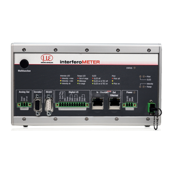
interferoMETER IMS5400-DS19
MICRO-EPSILON interferoMETER IMS5400-DS19 Manuals
Manuals and User Guides for MICRO-EPSILON interferoMETER IMS5400-DS19. We have
3
MICRO-EPSILON interferoMETER IMS5400-DS19 manuals available for free PDF download: Operating Instructions Manual, Quick Manual
MICRO-EPSILON interferoMETER IMS5400-DS19 Operating Instructions Manual (146 pages)
Brand:
MICRO-EPSILON
| Category:
Industrial Equipment
| Size: 13 MB
Table of Contents
Table of Contents
3
Safety
9
Symbols Used
9
Warnings
9
Notes on CE Marking
9
Intended Use
10
Proper Environment
10
Laser Class
11
Functional Principle, Technical Data
12
Short Description
12
Measuring Principle
12
Term Definitions
13
Operating Modes
13
Sensors
13
Technical Data IMS5400
14
Technical Data IMS5400-TH
15
Technical Data IMS5600
16
Delivery
17
Unpacking/Included in Delivery
17
Storage
17
Installation
18
Imc5X00 Controller
18
Controller Operating Elements
19
Leds Controller
20
Electrical Connections Controller
21
Connection Possibilities
21
Handling of Pluggable Screw Terminals
21
Grounding, Shielding
21
Supply Voltage (Power)
22
Rs422
22
Ethernet, Ethercat
22
Analog Output
23
Switching Outputs (Digital I/O)
24
Synchronization (Inputs/Outputs)
25
Triggering
26
Encoder Inputs
27
Sensor Cable
27
Sensors
29
Sensor Dimensions
29
Start of Measuring Range
30
Mounting, Mounting Adapter
31
Operation
32
Initial Operation
32
Control Via Ethernet
32
Requirements
32
Access Via Web Interface
33
Select a Sensor
34
Button Multifunction
34
Positioning the Target, Distance Measurement
35
Positioning the Target, Thickness Measurement
36
Measurement Configuration, Signal Quality
36
FFT Signal
40
Distance and Thickness Measurement with Web
42
Load / Save Settings
44
Advanced Settings
45
Inputs
45
Synchronization
45
Encoder
45
Key Function
45
Input Level
45
Termination
45
Data Recording
46
Measuring Rate
46
Masking the Evaluation Range
47
Exposure Mode
47
Detection Threshold
48
Measpeak Sorting
49
Number of Peaks
51
Material Selection
54
Triggering
56
General
56
Triggering Data Recording
57
Triggering Data Output
57
Trigger Time Difference
57
Signal Processing, Calculation
58
Data Source, Parameter, Programs
58
Definitions
59
Measurement Averaging
60
Moving Average
60
Recursive Average
61
Median
62
Postprocessing
63
Zeroing, Mastering
63
Statistics
64
Data Reduction, Output Data Rate
65
Error Handling (Hold Last Value)
65
Outputs
66
General
66
Rs422
66
Data Output Ethernet
66
Analog Output
67
Calculation of the Measurement Value at the Current Output
68
Calculation of the Measurement Value at the Voltage Output
68
Characteristics Distance Value and Analog Output
69
Digital Outputs, Limit Value Monitoring
70
Data Output, Interface Selection
70
Ethernet Settings
71
System Settings
72
Unit Website
72
Language Support
72
Key Lock
72
Load and Safe
72
Import, Export
73
Access Authorization
74
Reset Controller
75
Light Source
75
Material Table
75
Switching between Ethernet and Ethercat
75
Thickness Measurement
76
Requirements
76
Sensor Selection
76
Material Selection
76
FFT Signal
77
Measurement Chart
77
Disclaimer
78
Service, Repair
78
Decommissioning, Disposal
78
Appendix
79
A 1 Accessories, Services
79
A 2 Factory Settings
80
A 3 ASCII Communication with Controller
81
A 3.1 General
81
A 3.2 Commands Overview
81
A 3.3 General Commands
84
A 3.3.1 General
84
Help
84
Controller Information
84
Reply Type
84
A 3.3.1.4 Paramter Overview
84
A 3.3.1.5 Synchronization
85
A 3.3.1.6 Termination Resistor at Sync/Trig Input
85
A 3.3.1.7 Booting the Sensor
85
A 3.3.1.8 Reset Counter
85
A 3.3.2 User Level
86
A 3.3.2.1 Changing the User Level
86
A 3.3.2.2 Changing to User Level
86
A 3.3.2.3 Querying the User Level
86
A 3.3.2.4 Defining a Standard User
86
A 3.3.2.5 Changing the Password
86
Sensor
87
A 3.3.3.1 Info about Calibration Tables
87
A 3.3.3.2 Sensor Number
87
Sensor Information
87
Pilot Laser
87
Sled
87
A 3.3.4 Triggering
88
A 3.3.4.1 Select Trigger Source
88
A 3.3.4.2 Output of Triggered Values, With/Without Averaging
88
A 3.3.4.3 Trigger Type
88
A 3.3.4.4 Active Level Trigger Input
88
A 3.3.4.5 Software Trigger Pulse
88
A 3.3.4.6 Number of Output Measurement Values
88
A 3.3.4.7 Trigger Level Trigin
88
A 3.3.4.8 Maximum Encoder Triggering
89
Minimum Encoder Triggering
89
A 3.3.4.10 Step Size Encoder Triggering
89
A 3.3.4.11 Example
89
A 3.3.5 Encoder
90
A 3.3.5.1 Encoder Interpolation Depth
90
A 3.3.5.2 Effect of the Reference Track
90
A 3.3.5.3 Encoder Value
90
A 3.3.5.4 Setting Encoder Value Per Software
90
A 3.3.5.5 Reset the Detection of the First Marker Position
90
A 3.3.5.6 Maximimum Encoder Value
90
A 3.3.5.7 Encoder3 On/Off
90
A 3.3.6 Interfaces
91
A 3.3.6.1 Ethernet IP Settings
91
A 3.3.6.2 Setting for Ethernet Transmission of Measured Values
91
A 3.3.6.3 Setting the RS422 Baud Rate
91
A 3.3.6.4 Change Ethernet / Ethercat
91
A 3.3.6.5 Measurements Per Frame
91
A 3.3.6.6 TCP On/Off
91
A 3.3.7 Parameter Management, Load / Save Settings
92
A 3.3.7.1 Safe / Load Connection Settings
92
A 3.3.7.2 Show Changed Parameters
92
A 3.3.7.3 Export of Parameter Sets to PC
92
A 3.3.7.4 Import of Parameter Sets from PC
92
A 3.3.7.5 Default Settings
92
A 3.3.7.6 Editing, Storing, Displaying, Deleting Measurement Settings
93
Measurement
94
A 3.3.8.1 Measuring Rate
94
A 3.3.8.2 Masking the Evaluation Ranges
94
Peak Detection Threshold
94
Material Data Base
95
Materialtable
95
A 3.3.9.2 Select Material
95
A 3.3.9.3 Display Material Properties
95
A 3.3.9.4 Edit Material Table
95
A 3.3.9.5 Material Ergänzen
95
A 3.3.9.6 Determining the Material Composition of the Target
95
A 3.3.9.7 Defining a Medium in Front of the Target
96
A 3.3.9.8 Delete a Material
96
A 3.3.9.9 Number of Peaks
96
A 3.3.10 Measurement Value Processing
96
A 3.3.10.1 List of Possible Displacement and Thickness Signals for Statistical Calculation
96
A 3.3.10.2 Generate Statistic Signals
96
A 3.3.10.3 List of Statistical Signals
96
A 3.3.10.4 Reset Statistical Calculation
96
A 3.3.10.5 Statistics Eample
97
A 3.3.10.6 List of Signals Which Can be Parameterized
98
A 3.3.10.7 Master Signal Parameterization
98
A 3.3.10.8 List of Possible Signals for Mastering
98
A 3.3.10.9 Masters / Zero
98
A 3.3.10.10 Mastering Example
98
A 3.3.10.11 Channel Computation
100
A 3.3.10.12 List of Possible Calculation Signals
100
A 3.3.11 Data Output
101
A 3.3.11.1 Selection of Digital Output
101
A 3.3.11.2 Data Output Rate
101
A 3.3.11.3 Reduction Counter of Measurement Value Output
101
A 3.3.11.4 Error Processing
101
A 3.3.12 Select Measurement Values to be Output
102
A 3.3.12.1 General
102
A 3.3.12.2 Data Selection of Ethernet
102
A 3.3.12.3 List of Possible Ethernet Signals
102
A 3.3.12.4 List of Selected Signals, Transfer Sequence Via Ethernet
102
A 3.3.13 Switching Outputs
103
A 3.3.13.1 Error Switching Outputs
103
A 3.3.13.2 Setting the Signal to be Evaluated
103
A 3.3.13.3 List of Possible Signals for Error Output
103
A 3.3.13.4 Setting Limit Values
103
A 3.3.13.5 Setting Value
103
A 3.3.13.6 Switching Behavior for Error Outputs
103
A 3.3.14 Analog Output
104
A 3.3.14.1 Data Selection
104
A 3.3.14.2 List of Possible Signals for Analog Output
104
A 3.3.14.3 Output Range
104
A 3.3.14.4 Setting the Scaling of DAC
104
A 3.3.14.5 Setting the Scaling Range
104
A 3.3.15 Key Functions
105
A 3.3.15.1 Multifunction Button
105
A 3.3.15.2 Signal Selection for Mastering with Multifunction Button
105
A 3.3.15.3 Key Lock
105
A 3.4 Measured Value Format
106
A 3.4.1 Structure
106
A 3.4.2 Exposure Time
106
A 3.4.3 Encoder
106
A 3.4.4 Measured Value Counter
106
A 3.4.5 Time Stamp
106
A 3.4.6 Measurement Data (Displacements and Signal Quality)
107
A 3.4.7 Trigger Time Difference
107
A 3.4.8 Statistical Values
107
A 3.5 Measurement Data Format
108
A 3.5.1 Measurement Data Transmission to a Server Via Ethernet
108
A 3.5.1.1 General
108
A 3.5.1.2 Measurement Frame
109
A 3.5.1.3 Example
109
A 3.5.1.4 Error Codes Ethernet Interface
109
A 3.5.2 Ethernet FFT Signal Transmission
109
A 3.6 Warning and Error Messages
110
A 4 Ethercat Documentation
112
A 4.1 General
112
A 4.2 Switching between Ethernet and Ethercat
112
A 4.3 Introduction
113
A 4.3.1 Structure of Ethercat® Frames
113
A 4.3.2 Ethercat® Services
113
A 4.3.3 Addressing and Fmmus
114
A 4.3.4 Sync Managers
114
A 4.3.5 Ethercat State Machine
114
A 4.3.6 Canopen over Ethercat
115
A 4.3.7 Process Data Object Mapping (PDO Mapping)
115
A 4.3.8 Service Data SDO Service
115
Coe Object Directory
116
Communication-Specific Standard Objects
116
A 4.4.1.1 Overview
116
A 4.4.1.2 Object 1000H: Device Type
116
A 4.4.1.3 Object 1008H: Manufacturer's Device Name
116
A 4.4.1.4 Object 1009H: Hardware Version
116
A 4.4.1.5 Object 100Ah: Software Version
116
A 4.4.1.6 Object 1018H: Device Identification
116
A 4.4.1.7 Txpdo Mapping
117
A 4.4.1.8 Object 1C00H: Type of Synchronization Manager
118
A 4.4.1.9 Object 1C12H: Rxpdo Assign
118
A 4.4.1.10 Object 1C13H: Txpdo Assign
118
A 4.4.1.11 Object 1C33H: Synchronization Manager Input Parameters
119
Manufacturer-Specific Objects
120
Overview
120
A 4.4.2.2 Object 2001H: User Level
121
A 4.4.2.3 Object 2005H: Controller Info (Continued)
121
A 4.4.2.4 Objekt 2020H: Load, Save, Factory Settings
121
A 4.4.2.5 Objekt 2021H: Preset
122
A 4.4.2.6 Objekt 2022H: Measurement Settings
122
A 4.4.2.7 Object 203Fh: Sensor Error
122
A 4.4.2.8 Object 2101H: Reset
123
A 4.4.2.9 Object 2105H: Factory Settings
123
A 4.4.2.10 Object 2107H: Reset Counter
123
A 4.4.2.11 Object 2133H: SLED Light Source
123
A 4.4.2.12 Object 2134H: Pilot Laser
123
A 4.4.2.13 Object 2141H: Request FFT Signal
123
A 4.4.2.14 Object 2142H: Share FFT Signal
123
A 4.4.2.15 Object 2150H: Sensor
123
A 4.4.2.16 Object 2152H: Sensor Selection
124
A 4.4.2.17 Objekt 2156H: Number of Peaks for Multilayer Materials
124
A 4.4.2.18 Object 2162H: Peak Options
124
A 4.4.2.19 Object 21B0H: Digital Interfaces
124
A 4.4.2.20 Object 21B1H: Select Interface
124
A 4.4.2.21 Object 21C0H: Ethernet
125
A 4.4.2.22 Objekt 21D0H: Analog Output
125
A 4.4.2.23 Object 21F3H: Switching Output 1
126
A 4.4.2.24 Object 2251H: Measuring Rate
126
A 4.4.2.25 Object 24A0H: Keylock
126
A 4.4.2.26 Object 24A2H: Multifunction Button
127
A 4.4.2.27 Object 25A0H: Encoder
127
A 4.4.2.28 Object 25A1: Encoder3
128
A 4.4.2.29 Object 2711H: Masking the Evaluation Range
128
A 4.4.2.30 Objekt 2800H: Material Information
128
A 4.4.2.31 Object 2802H: Edit Material Table
128
A 4.4.2.32 Object 2803H: Existing Materials
129
A 4.4.2.33 Object 2804H: Select Material
129
A 4.4.2.34 Objekt 2805H: Material between Sensor and 1St Layer
129
A 4.4.2.35 Object 2A00H: Mastering
129
A 4.4.2.36 Object 2A10H: Statistics
130
A 4.4.2.37 Object 2C00H: Measured Value Calculation
131
A 4.4.2.38 Object 2E00: User Signals
132
A 4.5 Mappable Objects - Process Data
133
Error Codes for SDO Services
134
A 4.7 Oversampling
135
A 4.8 Calculation
136
A 4.9 Operational Modes
136
A 4.9.1 Free Run
136
A 4.9.2 Distributed Clocks SYNC0 Synchronization
136
A 4.10 FFT Signal Via SDO
136
STATUS Leds in Ethercat Operation
137
A 4.12 Ethercat Configuration with the Beckhoff Twincat© Manager
138
A 5 Data Format RS422
141
A 5.1 Bit Structure
141
A 5.2 Description
141
A 5.3 Examples
142
A 6 Telnet
144
General
144
A 6.2 Verbindungsaufbau
144
A 6.3 Error Messages
144
Advertisement
MICRO-EPSILON interferoMETER IMS5400-DS19 Quick Manual (32 pages)
Brand:
MICRO-EPSILON
| Category:
Measuring Instruments
| Size: 3 MB
Table of Contents
Table of Contents
2
General
3
Symbols Used
3
Warnings
3
Intended Use
4
Proper Environment
4
Glossary
5
Laser Safety
5
Operating Modes
6
Setup, Connection Options
6
Sensor Cable
7
Mounting, Mounting Adapter
7
Pluggable Screw Terminals
8
Leds Controller
9
Button Multifunction
10
Initial Operation
11
Select a Sensor
11
Start of Measuring Range, Working Distance
11
Positioning the Target, Distance Measurement
12
System Settings
12
Positioning the Target, Thickness Measurement
13
Measurement Configuration
13
Signal Quality
14
FFT Signal Check
15
Number of Peaks
16
Material Selection
23
Output Values
27
Distance and Thickness Measurement, Web Page Display
28
Data Output, Interface Selection
30
Ethernet
30
Set IP Address
31
Disclaimer
31
Service, Repair
32
Service & Repair
32
MICRO-EPSILON interferoMETER IMS5400-DS19 Quick Manual (32 pages)
Brand:
MICRO-EPSILON
| Category:
Measuring Instruments
| Size: 3 MB
Table of Contents
Table of Contents
2
General
3
Symbols Used
3
Warnings
3
Intended Use
4
Proper Environment
4
Glossary
5
Laser Safety
5
Operating Modes
6
Setup, Connection Options
6
Sensor Cable
7
Mounting, Mounting Adapter
7
Pluggable Screw Terminals
8
Leds Controller
9
Button Multifunction
10
Initial Operation
11
Select a Sensor
11
Start of Measuring Range, Working Distance
11
Positioning the Target, Distance Measurement
12
Positioning the Target, Thickness Measurement
13
Messpeak Sorting
14
Number of Peaks
17
Material Selection
21
Measurement Configuration
25
Signal Quality
26
FFT Signal Check
27
Distance and Thickness Measurement, Web Page Display
28
Data Output, Interface Selection
30
Ethernet
30
Set IP Address
31
Disclaimer
31
Service, Repair
32
Advertisement
Advertisement
Related Products
MICRO-EPSILON interferoMETER IMS5400-DS
MICRO-EPSILON interferoMETER IMS5400-TH
MICRO-EPSILON interferoMETER IMS5400-TH45
MICRO-EPSILON interferoMETER IMS5400-TH70
MICRO-EPSILON interferoMETER IMS5400-DS19/MP
MICRO-EPSILON interferoMETER IMS5400-TH45/MP
MICRO-EPSILON interferoMETER IMS5400-TH70/MP
MICRO-EPSILON interferoMETER IMS5420
MICRO-EPSILON interferoMETER IMS5420-TH
MICRO-EPSILON interferoMETER IMS5420IP67MP-TH
MICRO-EPSILON Categories
Measuring Instruments
Accessories
Industrial Equipment
Security Sensors
Controller
More MICRO-EPSILON Manuals
Login
Sign In
OR
Sign in with Facebook
Sign in with Google
Upload manual
Upload from disk
Upload from URL