MICRO-EPSILON interferoMETER IMS5400-DS19 Quick Manual
Hide thumbs
Also See for interferoMETER IMS5400-DS19:
- Operating instructions manual (146 pages) ,
- Quick manual (32 pages)

Subscribe to Our Youtube Channel
Related Manuals for MICRO-EPSILON interferoMETER IMS5400-DS19


Summary of Contents for MICRO-EPSILON interferoMETER IMS5400-DS19
- Page 1 Quick Manual interferoMETER IMS5400-DS19 IMS5400-DS19/MP IMS5600-DS19 IMS5400-TH45 IMS5400-TH45/MP IMS5600-DS19/MP IMS5400-TH70 IMS5400-TH70/MP...
-
Page 2: Table Of Contents
Koenigbacher Str. 15 94496 Ortenburg / Germany Tel. +49 (0) 8542 / 168-0 Fax +49 (0) 8542 / 168-90 You can find further information about the measurement e-mail info@micro-epsilon.com system in the operating instructions. They are available at: www.micro-epsilon.com www.micro-epsilon.com/download/manuals/ man--interferoMETER-5x00--en.pdf... -
Page 3: General
General General Symbols used The following symbols are used in this document: CAUTION Indicates a hazardous situation which, if not avoided, may result in minor or moderate injury. NOTICE Indicates a situation that may result in property damage if not avoided. Indicates a user action. -
Page 4: Intended Use
General Intended Use - The interferoMETER measuring system is designed for use in an industrial environments and domestic areas. It is used for ƒ measuring displacement, distance, profile, thickness and surface inspection ƒ monitoring quality and checking dimensions. - The measuring system must only be operated within the limits specified in the technical data, see operating instruc- tions chap. -
Page 5: Glossary
Laser Safety Glossary Laser Safety The interferoMETER measuring system works with a = Measuring range pilot laser of a wavelength of 635 nm (visible / red) offering max. power of < 0.01 mW and a measuring SMR = Start of measuring range laser of a wavelength of 840 nm with a max. -
Page 6: Operating Modes
Operating Modes Operating Modes Setup, Connection Options Connect the components together and mount the The interferoMETER measuring system provides highly sensors into the clamps. accurate measurements of - distances against visually dense materials with 2-Port Switch / light-diffusing or reflective surfaces EtherCAT - thicknesses for transparent layer materials. -
Page 7: Sensor Cable
Setup, Connection Options Sensor Cable General Rules As a matter of principle, avoid: Sensor and controller are connected through an - any contamination of the connector, e.g., dust or finger optical fiber. prints - Do not shorten or extend the optical fiber. - unnecessary mating cycles. -
Page 8: Pluggable Screw Terminals
Setup, Connection Options Pluggable Screw Terminals Description Comments 0 ... 5 V; 0 ... 10 V; R appr. 50 Ohm Analog Out Voltage output 5.5 V / 10.9 V with error, outside measuring range U/I out 4 ... 20 mA; R ≤... -
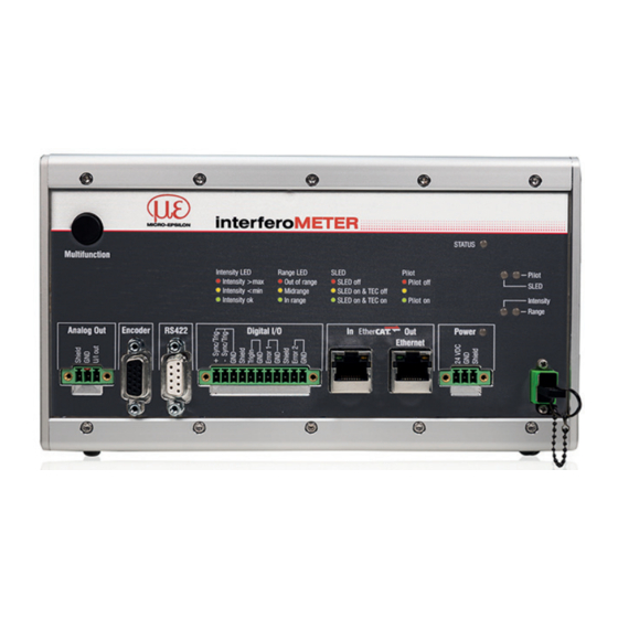
Page 9: Leds Controller
LEDs Controller LEDs Controller Power on Green Operating voltage available No error Status If EtherCAT is active, meaning of the LED is conform with the Ether-CAT guidelines. The LED’s Intensity and Range Signal in saturation flashes with their current color Yellow Signal too low during a synchronization error. -
Page 10: Button Multifunction
LEDs Controller Button Multifunction The Multifunction button of the controller has multiple functions. It enables, e.g., to operate the light source. The button is factory-set to the Pilotlaser on/off feature. Set / reset Starts or stops the master measurement of the selected signals master value Pilot laser Turns on/off the pilot laser... -
Page 11: Initial Operation
Operating range You can check the IP address of the controller, that are connected to a PC / network, with the sensorTOOL. exe program. This program is available online at https:// Working distance www.micro-epsilon.com/download/software/sensor- Thickness sensor TOOL.exe. IMS5x00 Page 11... -
Page 12: Positioning The Target, Distance Measurement
Initial Operation Positioning the Target, Distance Measurement You can also position the sensor using the FFT sig- . The interferometric measuring principle provides The red-light pilot laser supports you in aligning the measurement values in front of and behind the actual sensor to the target during commissioning. -
Page 13: Positioning The Target, Thickness Measurement
Initial Operation Positioning the Target, Thickness Measurement The LED Range on the controller front indicates the position of the target in relation to the sensor. The red-light pilot laser supports you in aligning the No target or target outside the sensor to the target during commissioning. -
Page 14: Messpeak Sorting
Initial Operation Messpeak Sorting The selection of peak/peaks dictates which region in the signal is used for the distance or thickness measurement. Switch to material selection by going to Settings > Data recording. Switch to the chart type FFT. Choose between First peak and Highest peak. Controller IMC5400, IMC5600 Thickness Distance... - Page 15 Initial Operation Controller IMC5400/MP , IMC5600/MP Thickness Distance Each peak represents a thickness value. The peaks are count- Each detected peak represents a distance value. The peaks ed starting at the start of the measuring range (for the thinnest are counted starting at the start of the measuring range (short layer) toward the end of the measuring range (for the thickest distance between sensor and target) in the direction of the end layer).
- Page 16 Initial Operation Range [%] Range [%] Evaluation starts with the highest peak, e.g. 3 out of 4 peaks The number of peaks of the FFT signal that are used for evaluation in distance and thickness measurement are to be determined separately, see Chap. Number of Peaks. In the case of a target consisting of several transparent layers, the material must be assigned for each layer, see Chap.
-
Page 17: Number Of Peaks
Make sure to count the peaks in the correct manner, see Chap. Messpeak Sorting. The standard systems IMS5400-DSxx, IMS5400-THxx and IMS5600-DSxx evaluate one layer. If no distances need to be determined for a measurement, Micro-Epsilon recommends using an IMS5400MP- THxx. - Page 18 Initial Operation Example of a layer of glass and gap, measpeak sorting: First, corresponding material selection Thickness Distance IMP-TH IMP-DS Peak 1 Peak 2 Peak B Peak 3 Peak C Peak 2 Peak 1 Peak A Peak 3 Range [%] Range [%] During a distance mea- surement on transparent...
- Page 19 Initial Operation Example of laminated glass from three layers, measpeak sorting: First, corresponding material selection Thickness Distance IMP-DS IMP-TH Peak 1 Peak D Peak 4 Peak 5 Peak E Peak F Peak 2 Peak 6 Peak A Peak 1 Peak 3 Peak B Peak 2 Peak 3...
- Page 20 Initial Operation Example of two layers of the same thickness; measpeak sorting: First, corresponding material selection Distance IMP-DS Thickness IMP-TH Peak 1 Peak A Peak 1 Peak B Peak 2 Peak 2 Peak A Peak 1 Peak 3 Range [%] Range [%] Peak 1 is duplicated because the two layers of The thickness can also be determined...
-
Page 21: Material Selection
Initial Operation Material Selection The refractive index needs to be corrected in the controller for an exact distance or thickness measurement. Only air may be present between the sensor face and the measuring object (Material Infront); other media such as water or alcohol are not permissible. - Page 22 Initial Operation The surface area of the following material is also required for calculating the distances and thicknesses. Click the icon to change an existing entry. Click the icon to add another material. Click the icon to save another or changed material. Click the icon to cancel the operation without saving.
- Page 23 Initial Operation Thickness Controller IMC5400MP , IMC5600MP Distance Switch to material selection by going to Settings > Data recording. Assign the materials to the individual layers according to the target used. The IMS5400-THxx and IMS5400-THxx/ MP thickness systems output the coating Peak 1 thickness(es) directly.
- Page 24 Initial Operation Thickness Controller IMC5400MP , IMC5600MP Distance Compared to the example above, the thickness of the lower layer (blue) has in- creased and is larger than the upper layer. Peak 1 Layer 1, BK7 For this case, the material selection must Peak 3 be adjusted.
-
Page 25: Measurement Configuration
Initial Operation Measurement Configuration Then, you can apply your own settings (setups). When saving a modified preset, the web interface displays a Common measurement configurations (presets) for dialog for entering a setup name. This prevents presets various target surfaces are stored on the controller. This from being overwritten by accident. -
Page 26: Signal Quality
Initial Operation Signal Quality Using the Signal quality function, you can influence the measuring rate and the respective averaging. Averaging with the Median function is specified by the preset. The subsequent moving averaging is specified by the Signal quality function. Averaging Description Static... -
Page 27: Fft Signal Check
Initial Operation FFT Signal Check Go to the Measurement chart menu. Show FFT signal display with FFT. The signal in the chart window shows the distance be- tween sensor and target or the target thickness. Left 0 % (small distance) and right 100 % (large distance). -
Page 28: Distance And Thickness Measurement, Web Page Display
Distance and Thickness Measurement, Web Page Display Distance and Thickness Measurement, Web Page Display Align the sensor vertically to the target object. Then, move the sensor (or the target) closer, until you more or less reach the start of measuring range for your sensor. - Page 29 Distance and Thickness Measurement, Web Page Display Auto (= automatic scaling) or Manual The LED visualizes the status of the transmission of measured values: (= manual setting) allow for scaling the measure- - green: transmission of measured values is run- ment axis (Y axis) of the graphic.
-
Page 30: Data Output, Interface Selection
Data Output, Interface Selection Data Output, Interface Selection The controller supports - three digital interfaces that can be used in parallel for data output, ƒ Ethernet: enables fast data transfer, but provides no real-time capabilities (packet-based data transfer). Both measurement and FFT data can be transferred. -
Page 31: Set Ip Address
MICRO-EPSILON or to your distribu- tor / retailer. MICRO-EPSILON undertakes no liability whatsoever for damage, loss or costs caused by or related in any way to the product, in particular consequential damage, e.g., due to... -
Page 32: Service, Repair
If the cause of a fault cannot be clearly identified, please send the entire measuring system to: MICRO-EPSILON MESSTECHNIK GmbH & Co. KG Koenigbacher Str. 15 · 94496 Ortenburg / Germany Tel. +49 (0) 8542 / 168-0 · Fax +49 (0) 8542 / 168-90 X9691389-B012102MSC info@micro-epsilon.com ·...
Need help?
Do you have a question about the interferoMETER IMS5400-DS19 and is the answer not in the manual?
Questions and answers