JDS Uniphase DSAM-2600 Manuals
Manuals and User Guides for JDS Uniphase DSAM-2600. We have 2 JDS Uniphase DSAM-2600 manuals available for free PDF download: User Manual, Quick Start Manual
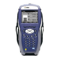
JDS Uniphase DSAM-2600 User Manual (362 pages)
DSAM series
Brand: JDS Uniphase
|
Category: Measuring Instruments
|
Size: 13 MB
Table of Contents
-
Assumptions
36 -
Conventions
38 -
Mode Keys
44 -
Shift Keys
44 -
The Keypad
48 -
Overview
68-
Sound70
-
-
-
Security85
-
Reset Meter87
-
Clone88
-
-
Printer77
-
RF Network80
-
-
About Me74
-
-
Diagnostic90
-
-
-
-
FDR Settings103
-
Voipcheck107
-
Downstream Plans118
-
Other Settings105
-
-
Limit Sets98
-
-
-
Overview117
-
-
-
Autotests128
-
Build New Plan131
-
-
-
-
PC Connection136
-
Access Mode141
-
Overview
142-
-
-
Synchronization146
-
WFA Browser149
-
-
-
Work Folders142
-
-
-
Overview148
-
Error Messages152
-
Local Browser152
-
Softkeys150
-
-
-
Combo Test156
-
Video Channels156
-
Cable Modem156
-
-
Autotests Tab
156-
-
-
Voipcheck View173
-
-
-
Cable Modem Test182
-
-
Level190
-
Miniscan190
-
Full Scan190
-
Tilt190
-
Constellation190
-
Fdr190
-
QAM Ingress190
-
Hum190
-
Dqi191
-
Return Loopback191
-
-
Level
191-
Frequency Tuning191
-
Channel Tuning192
-
-
Graph199
-
Errored Seconds195
-
C/N196
-
-
-
Miniscan
198 -
Full Scan
201-
Graph203
-
Tilt
208-
Measuring Tilt208
-
-
Constellation
214-
Impairments216
-
Gain Compression218
-
I/Q Imbalance218
-
Fdr
220-
-
Graph223
-
Progress Bar223
-
Status223
-
Using Zoom223
-
-
QAM Ingress
227-
Symbol Rate227
-
Transmit Status227
-
Graph229
-
-
Hum Analysis
230 -
Dqi
232 -
Return Loopback
234 -
-
Saving Results
238 -
Docsis
244-
Ethernet244
-
Introduction244
-
Voip244
-
-
-
Step 4251
-
LEVEL Headroom252
-
MER Headroom252
-
Packet Loss256
-
Step 1250
-
Step 2250
-
Step 3250
-
Jitter262
-
Packet Loss262
-
Delay263
-
Mos263
-
R-Value263
-
-
Ethernet
265-
Packet Loss Test265
-
Ping Test265
-
Throughput Test265
-
Voip
274-
-
-
Declining a Call281
-
-
Accepting a Call280
-
-
Field View288
-
-
-
-
Graph295
-
-
Field View
298-
-
Graph305
-
-
-
Forward Sweep312
-
Reverse Sweep312
-
Sweepless Sweep313
-
-
Forward Sweep
313-
-
-
Graph316
-
-
-
Reverse Sweep
319-
-
Graph322
-
-
Sweepless Sweep
325-
-
Graph327
Advertisement
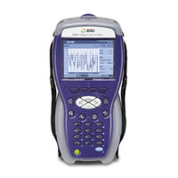
JDS Uniphase DSAM-2600 Quick Start Manual (84 pages)
Field Meter
Brand: JDS Uniphase
|
Category: Measuring Instruments
|
Size: 0 MB
Table of Contents
-
Assumptions12
-
Conventions13
-
-
-
Training78