Sign In
Upload
Manuals
Brands
Integra Manuals
Medical Equipment
Cusa Excel
Integra Cusa Excel Manuals
Manuals and User Guides for Integra Cusa Excel. We have
4
Integra Cusa Excel manuals available for free PDF download: Service Manual, User Manual, Manual, Instructions For Use Manual
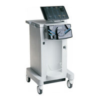
Integra Cusa Excel Service Manual (213 pages)
Ultrasonic Surgical Aspirator
Brand:
Integra
| Category:
Medical Equipment
| Size: 5 MB
Table of Contents
Table of Contents
6
Section 1. Service Personnel Safety
18
Safety Information
18
Warnings, Cautions, and Notices
18
General
19
Introduction
19
Unpacking and Installing the CUSA Excel System
19
Console Components
19
Technical Specifications
19
Checkout Procedures
19
Maintaining the CUSA Excel System
20
Troubleshooting
21
Replacement Procedures
21
Calibration
22
Repair Policy
22
Section 2. Introduction
24
For Your Information
24
Overview
25
Fragmentation
25
Tip Motion
25
Cooling
25
Irrigation
26
Aspiration (Suction)
27
Handpieces
28
Wide Variety of Tips
28
Section 3. Unpacking and Installing the CUSA Excel Surgical Aspirator System
30
The Responsibility of the Manufacturer
30
Unpacking the CUSA Excel System
31
Tools You will Need
31
Unpacking Procedure
31
Preparing the CUSA Excel Console for Use
37
Replacing the Power Connector
38
Section 4. Console Components
40
For Your Information
40
Console Overview and Structural Features
41
I.V. Pole
42
Control Panel
42
Arm and Arm Housing
42
Housing for Irrigation Pump Head and Suction Pinch Valve
42
Console Body
42
Shelf for Suction Canister
42
Casters
42
Control Panel
43
Alerts
44
Lap Mode, Prime, Test, and Status Buttons
44
Displays
44
Status Indicators
46
Setpoint Adjustment Buttons
46
Console Body Front Panel
47
Handpiece Connector Receptacle
47
Suction Pinch Valve
48
System Power Switch
48
Irrigation Pump Head
48
Contamination Guard
48
Retaining Bail for Suction Canister
48
Console Body Side Panel
49
Control Panel
50
Rotation Lock Handle
50
Housing for Irrigation Pump Head and Suction Pinch Valve
50
I.V. Pole
50
Arm and Arm Housing
50
Arm Release Tab
50
Cooling Water Reservoir
50
I.V. Pole Release Button
50
Console Body Rear Panel
51
Speaker
52
Volume Control
52
Footswitch Connector Receptacle
52
AC Main Switch
52
Fuses
52
Footswitch
52
AC Power Cord
54
Cord Wraps
54
Equipotential Grounding Lug
54
Label
54
Storage Compartment
54
Symbols on the Control Panel
55
Other Features
56
Filling the Cooling Water Reservoir
56
Raising/Lowering the Arm
56
Rotating the Control Panel
57
Adjusting the Tone Volume
57
Adjusting the I.V. Pole
58
Section 5. Technical Specifications
60
Console Dimensions
61
CUSA Excel Console
61
Footswitch
61
Console Subsystems
61
Ultrasonic
61
Fluidic System
62
Electrical Requirements
62
Input Power Source
62
Power Cords
62
Low Frequency Leakage
63
Duty Cycle
63
Environment
63
Standards and IEC Classifications
64
Class I Equipment (IEC 601-1)
64
Type BF Applied Part Equipment (IEC 601-1)
64
IPX - 8 (IEC 529, UL60601) Footswitch
64
Electromagnetic Interference
65
System Power off / Standby
65
Pinch Point in the Suction Pinch Valve
65
Fuse Replacement
65
Footswitch Symbols
65
Voluntary Standards
66
Statutory and Regulatory Requirements
66
EMC Compatibility
66
Handpieces
71
Nominal Frequencies
71
Dimensions
71
Tip Specifications
71
23 Khz
72
36 Khz
73
Section 6. Principles of Operation
74
How the Handpiece Works
75
Electromechanical Operation
75
Fragmentation
76
Cooling
76
How the Tissueselect Feature Works
77
Inherent Tissue Selectivity
78
Increasing Tissue Selectivity
78
Tissueselect Reduces Reserve Power to the Tip
79
Benefits of Tissueselect
81
A Common Misunderstanding of the Amplitude Setting
82
For Your Information
84
Section 7. Circuit Theory
84
Display Board
85
General Description
85
Fundamentals of Operation
85
Detailed Circuit Description
86
Machine Control Board
87
Introduction
87
Irrigation Pump
87
Suction Pump
87
Cooling Pump
89
Suction Valve
89
Amplitude Control
89
Valve Controls
90
Power Control Input and Output Signals
90
Voltage Regulators
91
Interface Connectors
91
Ultrasonics Board-Ultrasonic Generator
91
Fundamentals of Operation
91
The Main Frequency Loop
92
Bandpass Filter (BPF)
92
Agc/Error Amplifier Circuit
93
Phase Compensator
94
Driver Stage
94
Feedback Signal
95
Bias Circuitry
95
Frequency Selection Circuitry
95
System 24 V Power Supply Board
96
Ultrasonics Board-Other Circuits
96
Audible Alert and Operation Indicator
96
Valve Drivers
96
Power and Other Signal Connections
96
Inspections
98
Footswitch
98
Power Cord
99
Section 8. Checkout Procedures
98
Handpiece Test (Optional)
99
Power on Verification
99
For Your Information
104
Section 9. Maintaining the CUSA Excel System
104
Recommended Maintenance Schedule
105
Clean the CUSA Excel Console
106
Clean the Sterilizer Case
106
Maintain the Handpiece
106
Clean the Handpiece
107
Lubricate the Handpiece Connector O-Rings
108
Replace the Handpiece Connector O-Rings
108
Recalibrate the Handpiece
108
Maintain the Tip Torquing Set
109
Clean the Tip Torquing Set
109
Check the Torque on the Tip Torquing Wrench
109
Store the CUSA Excel System and Accessories
110
CUSA Console
110
Handpiece
110
Footswitch
110
CEM Nosecone
110
For Your Information
112
Section 10. Troubleshooting
112
Troubleshooting Safety
113
User Troubleshooting
113
Responding to Alerts
114
General Troubleshooting
117
Engineer Troubleshooting
126
Guidelines
126
Flowcharts
126
No Power
127
Handpiece Alarm
128
Footswitch Alarm
129
Cooling Water Alarm
130
Low Suction
131
Low Irrigation
133
Vibration Alarm
134
Section 11. Replacement Procedures
136
For Your Information
137
Console Covers
138
Open the Left Cover
139
Open the Right Cover
139
Open the Rear Cover
139
Re-Install the Left Cover
140
Re-Install the Right Cover
140
Re-Install the Rear Cover
140
System 24 Volt Power Supply
141
Remove the System 24 Volt Power Supply
141
Install the System 24 Volt Power Supply
141
Ultrasonics and Machine Control Printed Circuit Boards
143
Remove the Ultrasonics PCB
143
Install the Ultrasonics PCB
146
Remove the Control Panel Assembly
148
Remove the Machine Control PCB
149
Install the Machine Control PCB
149
Install the Control Panel Assembly
150
Control Head Components
150
Remove the Control Panel Assembly
152
Remove the Machine Control PCB
153
Remove the Control Panel Overlay
153
Remove the Display PCB
153
Install the Display PCB
154
Install the Control Panel Overlay
155
Install the Machine Control PCB
155
Install the Control Panel Assembly
155
Suction Control Valve
156
Remove the Suction Control Valve
156
Install the Suction Control Valve
162
Suction Pump and Controller Card
164
Remove the Suction Pump
164
Install the Suction Pump
169
Ready for Suction Pump Controller Card Replacement
170
Remove the Suction Pump Controller Card
171
Install the Suction Pump Controller Card
172
Suction Pinch Valve
173
Remove the Irrigation Pump Bezel
173
Remove the Suction Pinch Valve
173
Install the Suction Pinch Valve
175
Install the Irrigation Pump Bezel
175
Irrigation Pump Head and Gear Motor
176
Remove the Irrigation Pump Bezel
176
Remove the Irrigation Pump Head
176
Install the Irrigation Pump Head
177
Remove the Irrigation Pump Gear Motor
178
Install the Irrigation Pump Gear Motor
180
Replace the Irrigation Pump Bezel
180
Handpiece Flow Sensor
181
Remove the Handpiece Flow Sensor
181
Install the Handpiece Flow Sensor
183
Cooling Water Pump Tubing
184
Tools and Materials
184
Remove the Cooling Water Pump Head
184
Install Tubing and Re-Assemble the Cooling Water Pump Head
185
Cooling Water Reservoir O-Rings
185
O-Rings on the Cooling Water Reservoir Connectors
186
Fuses
187
For Your Information
188
Section 12. Calibration
188
DC Bias Power Supply
189
Tools/Equipment Needed for Calibrations
189
Motor for the Cooling Water Pump
190
Set up
190
Procedure
190
Suction Pump
190
Section 13. Repair Policy
192
Return Equipment for Service
193
Obtaining a Return Authorization Number
193
Returning the Console
193
Returning the Handpiece
200
Returning Circuit Boards
200
Ordering Replacement Parts
200
Integra Service Center
200
Ordering Replacement Parts
202
Section 14. Service Parts Lists
202
Replacement Parts
203
Handpiece Cooling
203
Irrigation
203
Miscellaneous
204
Power
204
Electronic Parts
205
Suction
205
Miscellaneous Spare Parts
209
Appendix A. Warranty
210
Advertisement
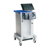
Integra Cusa Excel User Manual (189 pages)
Ultrasonic Surgical Aspirator System
Brand:
Integra
| Category:
Medical Equipment
| Size: 5 MB
Table of Contents
CUSA Excel™ Ultrasonic Surgical Aspirator System User's Guide
3
Preface
4
System Features
4
User's Guide Features
4
Organization
5
Intended Uses
6
Conventions Used in this Guide
7
List of Figures
8
Table of Contents
10
Part 1. Safety
18
Section 1. Patient and Operating Room Safety
19
Safety Information
19
Warnings, Cautions, and Notices
20
General
20
Setting up the CUSA Excel System
20
Shutting down the CUSA Excel System
21
Handpiece Components
21
Assembling the Handpiece in a Nonsterile Area
22
Disassembling CUSA Excel Handpieces
22
Troubleshooting the CUSA Excel System
22
Maintaining the CUSA Excel System
22
Appendix A. Technical Specifications
23
Part 2. Console
25
Section 2. Introduction to the Console
27
For Your Information
27
Overview
28
Fragmentation
28
Electromechanical Operation
28
Cooling
29
Irrigation
29
Aspiration (Suction)
30
Handpieces
31
Wide Variety of Tips
31
Intended Uses
32
Section 3. Console Components
33
For Your Information
33
Console Overview and Structural Features
34
I.V. Pole
35
Control Panel
35
Arm and Arm Housing
35
Housing for Irrigation Pump Head and Suction Pinch Valve
35
Console Body
35
Shelf for Suction Canister
35
Casters
35
Control Panel
36
Alerts
37
Lap Mode, Prime, Test, and Status Buttons
37
Displays
37
Status Indicators
39
Setpoint Adjustment Buttons
39
Console Body - Front Panel
40
Handpiece Connector Receptacle
40
Suction Pinch Valve
40
System Power Switch
40
Irrigation Pump Head
41
Contamination Guard
41
Retaining Bail for Suction Canister
41
Console Body - Side Panel
42
Rotation Lock Handle
43
Housing for Irrigation Pump Head and Suction Pinch Valve
43
I.V. Pole
43
I.V. Pole Release Button
43
Arm and Arm Housing
43
Arm Release Tab
43
Cooling Water Reservoir
43
Console Body - Rear Panel
44
Speaker
44
Volume Control
44
Footswitch Connector Receptacle
44
AC Main Switch
44
Fuses
45
Footswitch
45
AC Power Cord
47
Equipotential Grounding Lug
47
Labels
47
Cord Wrap
47
Storage Compartment
47
Symbols on the Control Panel
48
Section 4. Using CUSA Excel Console Controls
49
For Your Information
49
Using Power Switches
50
AC Main Switch
50
System Power Switch
50
Understanding the Control Panel
51
Footswitch Alert
51
Handpiece Alert
51
Wait/Cooling Water
52
Cooling Water Alert
52
Test
53
Vibration Alert Prime
53
Standby Status
54
Adjusting Setpoint Values
55
Aspiration
55
Irrigation
55
Amplitude
55
Tissueselect
55
Changing Functions
56
Run Status
56
Laparoscopic Mode
56
Quiet Function
56
Using Other Features
57
Filling the Cooling Water Reservoir
57
Raising/Lowering the Arm
57
Rotating the Control Panel
58
Adjusting the Tone Volume
58
Adjusting the I.V. Pole
59
Using TISSUE Select
60
Inherent Tissue Selectivity
61
Increasing Tissue Selectivity
61
Tissueselect Reduces Reserve Power to the Tip
62
Benefits of Tissueselect
64
A Common Misunderstanding of the Amplitude Setting
65
Section 5. Setting up the CUSA Excel System
67
For Your Information
67
Quick Reference - Setup
67
Handpiece Assembly
67
Console Assembly
67
Complete the Handpiece Assembly
69
Items Needed
69
Attach a Nosecone
70
Clip the Manifold Tubing to the Handpiece Cable
71
Prepare the System for Startup
73
At the Rear Panel
73
On the Side Panel: Cooling Water
73
On the Front Panel: Suction
74
On the Front Panel: Handpiece
75
Turn on the CUSA Excel System
76
Connect the Suction Tubing
76
Connect the Irrigation Tubing
78
Test the Handpiece
80
Test the CEM Nosecone
81
When the Surgeon Is Ready
82
Section 6. Shutting down the CUSA Excel System
84
Shut down the CUSA Excel System
85
Disconnect Suction Tubing, Irrigation Tubing, and the Handpiece
86
Clean the Console
89
Part 3. Handpieces and Accessories
90
Section 7. Introduction to Handpieces
91
For Your Information
91
Description
92
Functions
92
Configurations
93
Wide Variety of Tips
93
Section 8. Handpiece Components
95
For Your Information
95
Components of Assembled Handpieces
96
Handpiece
96
O-Rings
97
Nosecone
97
Tip
98
Flue
99
Manifold Tubing
99
Additional Components
100
Nonsterile Tip Torquing Base and Torque Wrench
100
Sterilizable Torque Bases
101
Sterile Torque Wrenches
101
Sterilizer Cases
102
Section 9. Assembling the Handpiece in a Nonsterile Area
105
For Your Information
105
Items Needed
106
Attach the Tip to the Connecting Body
108
Put on the O-Rings
110
Clip the Manifold Tubing to the Handpiece Cable (Optional)
111
Package the Handpiece for Sterilization
112
Items Needed
112
Section 10. Sterilizing Handpieces and Accessories
115
For Your Information
115
Sterilization Parameters
116
Handpieces Without Manifold Tubing
116
Handpieces with Manifold Tubing Attached
116
Sterilize the Handpiece
117
Sterilizing with Steam
117
Validation of Steam Sterilization Parameters
117
Section 11. Completing Handpiece Setup on the Sterile Field
119
For Your Information
119
Quick Reference - Setup
120
Handpiece Assembly
120
Complete the Handpiece Assembly
121
Items Needed
121
Attach a Nosecone
122
Clip the Manifold Tubing to the Handpiece Cable
124
Section 12. Disassembling Handpieces
128
For Your Information
128
Disassemble the Handpiece
129
Clean the Handpiece
132
Clean the Tip Torquing Set
133
Part 4. Troubleshooting and Maintenance
134
Section 13. Troubleshooting the CUSA Excel System
135
For Your Information
135
Responding to Alerts
136
General Troubleshooting
139
Section 14. Maintaining the CUSA Excel System
150
For Your Information
150
Quick Reference
151
Clean the Sterilizer Case
152
Maintain the Handpiece
152
Lubricate the Handpiece Connector O-Rings
152
Replace the Handpiece Connector O-Rings
152
Recalibrate the Handpiece
153
Store the CUSA Excel System and Accessories
153
CUSA Excel Console
153
Handpiece
153
Footswitch
153
CEM Nosecone
153
Return Equipment for Service
153
Obtaining a Return Authorization Number
154
Returning the Console
154
Returning Handpieces
154
Ordering Replacement Parts
154
Integra Service Centers
155
Part 5. Appendix
156
Appendix A. Technical Specifications
156
Console Dimensions
156
CUSA Excel Console
156
Footswitch
156
Console Subsystems
157
Ultrasonic
157
Fluidic System
157
Electrical Requirements
158
Input Power Source
158
Power Cords
158
Low Frequency Leakage
158
Duty Cycle
158
Environment
159
Standards and IEC Classifications
159
Class I Equipment (IEC 601-1
160
Type BF Applied Part Equipment (IEC 601-1
160
IPX - 8 (IEC 529, UL60601) Footswitch
160
Electromagnetic Interference
160
System Power off / Standby
160
Pinch Point in the Suction Pinch Valve
160
Fuse Replacement
160
Footswitch Symbols
161
Voluntary Standards
161
EMC Compatibility
161
Handpieces
162
Nominal Frequencies
162
Dimensions
162
Tip Specifications
162
23 Khz
163
36 Khz
164
Appendix B. Warranty
168
For Your Information
172
Items Needed
173
Assembly
176
Attach the Tip and O-Rings
176
Attach a Nosecone and Flue
178
Attach the Manifold Tubing
180
Disassembly to Change Tips on the Sterile Field
181
Disconnect the Manifold Tubing
182
Remove the Nosecone, O-Rings, and Tip
183
Disassembly after the Surgical Procedure
185
Reprocess the Handpiece
186
Clean the Handpiece
186
Reprocess the Sterilizable Torque Base
187
Clean the Base
187
Package the Handpiece for Sterilization
188
Package the Base for Sterilization
189
Sterilize the Handpiece and Base
189
Integra Cusa Excel Instructions For Use Manual (28 pages)
Handpiece/Extended Life Tip Maintenance Kit
Brand:
Integra
| Category:
Medical Equipment
| Size: 3 MB
Table of Contents
Table of Contents
3
Refurbishing Tool
4
Small Brush
4
Ferramenta de Renovação
6
Escova Pequena
6
Große Bürste
8
Polierer
8
Reinigungsstäbchen
8
Kleine Bürste
8
Herramienta de Restauración
10
Bastoncillos sin Pelusa
10
Cepillo Pequeño
10
Outil de Remise en État
12
Petite Brosse
12
Strumento DI Ripristino
14
Spazzola Piccola
14
Grote Borstel
16
Hulpinstrument
16
Kleine Borstel
16
Stor Borste
18
Polerverktyg
18
Luddfria Rengöringstussar
18
Liten Borste
18
Большая Щетка
20
Полировочная Шайба
20
Малая Щетка
20
整修器
22
改修ツール
24
小型ブラシ
24
Advertisement
Integra Cusa Excel Manual (43 pages)
Brand:
Integra
| Category:
Laboratory Equipment
| Size: 2 MB
Advertisement
Related Products
Integra CUSA NXT
Integra CUSA Clarity
Integra CUSA Excel Series
Integra CRW BiopsyPlus Kit
Integra CODMAN CERTAS Plus
Integra Cadence Total Ankle System
Integra C0023
Integra Codman VPV System
Integra CDC-3.4
Integra CDC-3
Integra Categories
Receiver
Medical Equipment
Laboratory Equipment
DVD Player
Stereo Receiver
More Integra Manuals
Login
Sign In
OR
Sign in with Facebook
Sign in with Google
Upload manual
Upload from disk
Upload from URL