Sign In
Upload
Manuals
Brands
Husqvarna Manuals
Motorcycle
TE 250-310 2012 I.E.
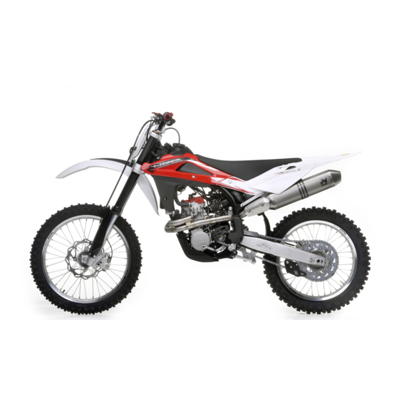
Husqvarna TE 250-310 2012 I.E. Manuals
Manuals and User Guides for Husqvarna TE 250-310 2012 I.E.. We have
1
Husqvarna TE 250-310 2012 I.E. manual available for free PDF download: Workshop Manual
Husqvarna TE 250-310 2012 I.E. Workshop Manual (376 pages)
Brand:
Husqvarna
| Category:
Motorcycle
| Size: 69.57 MB
Table of Contents
Table of Contents
10
St Edition (12-2011) -
2
Workshop Manual
3
Table of Contents
10
Engine
11
Transmission
12
Rear Brake
13
Electrical Components Location (TE)
14
Overall Dimensions
15
Weight
16
Table of Contents
34
Saddle Removal
36
Tank Removal
36
Valve Clearance Adjustment (te - TXC)
38
Valve Clearance Adjustment (TC)
39
Enrichener Lever Play Adjustment
42
Clutch Plate Replacement
44
Hydraulic Clutch Lever Adjustment and Fluid Level Check
45
Front Brake Lever Adjustment and Fluid Level Check
46
Rear Brake Pedal Position Adjustment
47
Rear Brake Fluid Level Check
48
Rear Brake Pedal Free Play Adjustment
48
Engine Oil Level Check
49
Engine Oil Replacement and Mesh Filters-Filter Cartridge Cleaning or Replacement
50
Coolant Level Check
51
Coolant Replacement
51
Air Filter Check (TC)
52
Air Filter Cleaning
52
Secondary Drive Chain Adjustment
55
Chain Lubrication
56
Disassembling and Cleaning
56
Lubricating a Chain Without O-Rings (TC)
56
Lubricating an O-Ring Chain
56
Washing a Chain Without O-Rings (TC)
56
Washing the Chain with or (te - TXC)
56
Suspension Setup According to Track Condition
57
Shock Absorber Adjustment
58
Shock Absorber Spring Preload Adjustment
59
Shock Absorber Compression and Rebound Damping Adjustment
60
Shock Absorber Springs
60
KAYABA Front Fork Adjustment
61
Steering Angle Adjustment
62
Steering Bearing Clearance Adjustment
62
Supply Hose Check
63
Exhaust System Check
64
Table of Contents
66
Foreword
67
Battery Removal (TE-TCX)
68
Saddle Removal
68
Side Panel Removal
68
Rear Chassis with Mudguard and Air Box Removal (TC)
69
Rear Chassis with Mudguard and Air Box Removal (TE-TXC)
69
Exhaust System Removal
72
Fuel Tank, Scoops and Spoiler Removal
76
Fuel Pump Removal (TC)
80
Fuel Pump Removal (te - TXC)
81
Condenser (TC)
82
Start-Up Relay Removal (TE-TXC)
82
Voltage Regulator Removal (TC)
84
Voltage Regulator Removal (TE-TXC)
84
Coil / Stick-Coil Removal (TC)
85
Ignition Coil Removal (TE-TXC)
85
Clutch Hose Removal
86
Horn Removal (TE)
86
Electric Cooling Fan Removal (TE-TXC)
87
Secondary Drive Chain Removal
87
Removal of Engine from Motorcycle
88
Radiator Removal
95
Thermostat Removal (TE-XC)
96
Table of Contents
98
Layout of Engine Components (te - TXC)
99
Layout of Engine Components (TC)
100
Camshaft Removal (te - TXC)
102
Camshaft Removal (TC)
104
Water Pump Disassembly
107
Valve Removal (TE-TXC)
115
Valve Removal (TC)
117
Engine Disassembly
118
Cylinder Removal
119
Piston Removal
119
Flywheel Removal
120
Kick Start Pedal Removal
121
Sprocket Removal
121
Oil Filter Removal
123
Clutch Cover Removal
124
Clutch Disassembly
125
Kick Start Disassembly
128
Slider Removal
128
Starter Motor Removal (TE-TXC)
130
Starter Drive Disassembly (TE-TXC)
132
Starter Motor Disassembly (TE-TXC)
132
Oil Pump Disassembly
135
Gear Shift Pedal and Selector Assembly Removal
136
Primary Drive Gear Removal
138
Crankcase Disassembly
139
Gearbox Disassembly
140
Crankshaft Disassembly
142
Table of Contents
144
Clearances
145
Cylinder Head
145
Valve Seat Refacing
146
Valve
147
Valve Spring (TE-TXC)
147
Rocker Arm Check (TC)
148
Valve Bucket Inspection (TE-TXC)
148
Valve Leak Check
150
Camshaft
151
Timing Chain and Gears
151
Timing Chain Tensioners
151
Cylinder
152
Piston
152
Cylinder to Piston Clearance (TE-TXC)
153
Piston Diameter
153
Piston Pin
153
Piston Ring to Cylinder Clearance
154
Piston Rings (TE-TXC)
154
Big End Axial Clearance
155
Piston Pin to Small End Clearance (A)
155
Piston Ring to Groove Clearance
155
Crankshaft
156
Crankshaft Straightness
156
Clutch
157
Clutch Spring
158
Friction Plate to Clutch Housing Clearance
158
Oil Pump
160
Drive Bushing Roundness
161
Shifter Forks and Gears
161
Table of Contents
164
General
165
Assembly and Lubrication Instructions
166
Crank- Alternator- Lubrication- Left Crankcase Half
166
Tightening Torque Figures
167
Assembly and Lubrication Instructions
168
Gearbox - Gear Shift Control (5 Speed)
168
Tightening Torque Figures
169
Assembly and Lubrication Instructions
170
Gearbox - Gear Shift Control (6 Speed)
170
Tightening Torque Figures
171
Assembly and Lubrication Instructions
172
Clutch- Kick Start- Lubrication- Right Crankcase Half
172
Tightening Torque Figures
173
Assembly and Lubrication Instructions
174
Right Crankcase Cover
174
Tightening Torque Figures
175
Assembly and Lubrication Instructions
176
Head - Cylinder - Piston - Timing System - Water Pump - Spark Plug
176
Te-Txc
176
Assembly and Lubrication Instructions
177
Head - Cylinder - Piston - Timing System - Water Pump - Spark Plug (TC)
177
Tightening Torque Figures
178
Input Shaft (5 Speed)
180
Output Shaft (5 Speed)
181
Input Shaft (6 Speed)
183
Output Shaft (6 Speed)
184
Crankcase Assembly
185
Gear Shift Control Assembly
190
Kick Start Assembly
194
Timing Chain and Primary Drive Assembly
195
Clutch Assembly
198
Sprocket Installation
200
Flywheel and Starter Motor Installation (TE-TXC)
201
Flywheel Installation (TC)
203
Piston and Cylinder Installation
204
Piston Ring Installation
204
Cylinder Head Gasket Selection Table
206
Water Pump Installation
210
Camshaft Installation (TE-TXC)
211
Camshaft Installation (TC)
213
Flywheel Cover Installation
215
Neutral Sensor Installation (TE-TXC)
216
Plug Refitting (TC)
217
Cylinder Head Cover, Spark Plug (TE-TXC)
218
Starter Motor Seat Cover Installation (TC)
218
Refitting of the Head Cylinder Cover, Spark Plug, Coil (TC)
219
Right Crankcase Assembly
220
Blow-By Tube Fitting/Filter (310)
222
Filter and Drain Plug (250)
222
Oil Feed Hose Installation
222
Gear Shift and Kick Start Pedal Installation
223
Installing the Engine and Assembling the Motorcycle
224
Table of Contents
226
Front Fork Removal
228
Front Suspension
228
Front Suspension (TC - TXC)
230
Service Instructions for Ø48USD Kayaba Fork
230
Front Suspension (TE)
242
Table of Contents
254
Lubrication Points (Grease)
255
Rear Suspension
255
Rear Shock Absorber Removal
256
Disassembling and Servicing the Swinging Arm
257
Servicing the Rear Suspension Drop and Drag Link
258
Servicing the Swinging Arm Shaft
258
Chain Roller, Chain Guide, Chain Slider
259
Table of Contents
262
Brake Disc
263
Braking System
263
Checking Brake Pads for Wear / Replacing the Pads
265
Bleeding the Front Braking System
266
Bleeding the Rear Braking System
267
Changing the Fluid
268
Table of Contents
272
Wiring Diagram (TC)
275
Wiring Diagram (TE)
276
Wiring Diagram (TXC)
277
Condenser (TC)
279
Electrical Components Location (TXC)
283
Checking Generator Stator Windings Resistance
286
Generator No-Load Performance
287
Ignition and Starter System (TC)
288
Ignition and Starter System (TE-TXC)
289
Charging System (TE-TXC)
291
Charging System Wiring Diagram
291
Charging System Inspections
292
Current Loss at the Battery (TE-TXC)
292
Regulated Voltage (TE-TXC)
292
Voltage Regulator
292
Voltage Regulator/Rectifier Inspection (TE-TXC)
292
Voltage Regulator/Rectifier Wiring Diagram
292
Electrical Starting System (TE-TXC)
293
Cranking Test
294
No-Load Test
294
Solenoid Starter Inspection (TE-TXC)
294
Starter Motor
294
Starter Motor Inspection (TE-TXC)
294
Starter Motor Test Curves (TE-TXC)
294
Starting System Inspection
294
Checking Coil Windings Resistance (TE-TXC)
295
Coil Windings Resistance Inspection (TC)
296
Electronic Control Unit (ECU)
297
Spark Plug
297
Gear Position Sensor Inspection (GPS: Gear Position Sensor) (TE-TXC)
298
Battery (TE-TXC)
299
Battery Charger
299
Headlamp Adjustment
300
Headlamp Bulbs Replacement
300
Headlamp, Tail Light (TE)
300
Number Plate Bulb Replacement
301
Tail Light Replacement
301
Handlebar Switches
302
Right-Hand Switch (TE-TXC)
303
Fuses (TE-TXC)
304
Semiconductor Parts
304
Relay Test (te - TXC)
305
Digital Dashboard, Warning Lights (TE)
306
Warning Lights Panel (TXC)
308
Charging System (TE-TXC)
309
Dashboard Replacement (TE)
309
Electronic Ignition System
309
Starting System (TE-TXC)
309
Troubleshooting
309
Wiring (TC)
310
Cable Routing and Electrical Parts Installation Instructions (TC)
311
Fuel Injection Control Unit Position (2) (TC)
311
Position of the Coil / Stick-Coil
311
Position of the Connectors Front Side
311
Position of the Voltage Regulator (3) (TC)
311
Air Temperature Sensor Connection (TC)
312
Connection of the Injector Sensor (7), Throttle Position Sensor (9), and MAP Sensor (8)
312
Fuel Pump Connector Position (TC)
313
Control Unit Connection (TC)
312
Ignition Coil / Stick-Coil Connection (TC)
312
Securing the Engine Stop Button Cable (TC)
313
Securing the Wiring (TC)
313
Condenser Connection (TC)
314
Voltage Regulator Connection (TC)
314
Connection of Alternator (TC)
314
Wiring (TE-TXC)
315
Cable Routing and Electrical Parts Installation Instructions "TE-TXC
316
Coil Position TE-TXC
316
Relay (1) and Fuses (2) Position (TE-TXC)
316
Turning Indicators Flasher (3) (TE) and Solenoid Starter
316
Battery Negative Cable Routing (TE-TXC)
317
Securing the Engine Ground to Chassis and Engine Ground to Battery Cables (8) (TE-TXC)
317
Securing the Starter Motor/Solenoid Starter Cable (TE-TXC)
317
Securing the Engine Ground / Chassis Ground Cables (10)
318
Wiring Connection to Voltage Regulator (TE-TXC)
318
Connection of Relays and Fuses (TE-TXC)
319
Electric Fan Connection (TE-TXC)
319
Injector Connection (TE-TXC)
319
Ignition Coil Connection (TE-TXC)
319
Fuel Pump Connector Position (TE-TXC)
320
MAQS Connector (TE-TXC)
320
Engine Water Temperature Connector (TE-TXC)
320
Lambda Sensor Position and Connector (TE-TXC)
320
Securing the Voltage Regulator Ground Cable (9) (TE-TXC)
318
Clip Installation on Fuse Holders
321
Ignition and Gear Sensor Cable Connection
321
Routing of Rear Chassis Cables, Tail Light Connection, Flasher Contactor
321
Dashboard Bracket Connectors (TE)
322
Headlamp, Front Turning Indicators, STOP Connection (TE)
322
Rear Stop Connection
322
Routing of Steering Head Tube Wiring
322
Double Map Connector (TE)
323
Horn Connector (TE)
323
Speed Sensor and Ignition Switch Connectors (TE)
323
Securing the Wiring Harness to Rear Chassis Left Side
324
Securing the Wiring Harness to Rear Chassis Right Side
324
Securing the Wiring Harness to the Chassis
324
Important
326
Table of Contents
328
Coolant Level Check
329
Cooling Circuit (TC)
330
Engine Cooling System Overhaul (TC)
331
Cooling Circuit (TE-TXC)
332
Engine Cooling System Overhaul (TE-TXC)
333
Table of Contents
336
Hydraulic Clutch System
337
Draining Clutch Fluid
338
Clutch Master Cylinder Servicing
339
Bleeding the Clutch System
340
Injection Fuel Feeding System (TE-TXC)
343
Injection Fuel Feeding System (TC)
344
Operation Manual for "HUSQVARNA SERVICE TOOL" for Injection Fuel Feeding System (TE-TXC)
345
Operation Manual for "HUSQVARNA SERVICE TOOL" for Injection Fuel Feeding System (TC)
347
Fuel Pump Test (TE-TXC)
348
Fuel Pump Test (TC)
349
Chassis
365
Lubrication Points (Lubricant)
366
Front Wheel
367
Removing the Front Wheel
368
Reassembling the Front Wheel
369
Speed Sensor (TE)
369
Rear Wheel
370
Removing the Rear Wheel
371
Wheel Servicing
372
Wheel Axle Warpage
372
Axle Runout over 100 MM
372
Wheel Spokes
373
Wheel Rim Warpage
373
Rear Chain Sprocket, Secondary Drive Sprocket and Chain
374
Checking Pinion and Sprockets for Wear
375
Advertisement
Advertisement
Related Products
Husqvarna TE 250 - 310 2011 I.E.
Husqvarna TE 250-450
Husqvarna TE 250 USA
Husqvarna TE 250 2010
Husqvarna 2013 TE 250R
Husqvarna TE 250-450-510
Husqvarna TE 250 2009
Husqvarna 2009 TE 250
Husqvarna TE 250
Husqvarna TE 250i 2021
Husqvarna Categories
Lawn Mower
Trimmer
Chainsaw
Motorcycle
Saw
More Husqvarna Manuals
Login
Sign In
OR
Sign in with Facebook
Sign in with Google
Upload manual
Upload from disk
Upload from URL