Sign In
Upload
Manuals
Brands
GE Manuals
Analytical Instruments
Sievers Innovox
GE Sievers Innovox Manuals
Manuals and User Guides for GE Sievers Innovox. We have
2
GE Sievers Innovox manuals available for free PDF download: Operation And Maintenance Manual
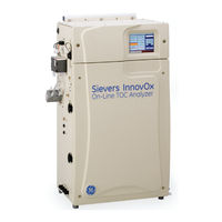
GE Sievers Innovox Operation And Maintenance Manual (270 pages)
TOC analyzer
Brand:
GE
| Category:
Analytical Instruments
| Size: 14.81 MB
Table of Contents
3
Identification Records
4
Table of Contents
10
List of Tables
11
List of Figures
15
Revision History
16
Confidentiality
17
Declaration of Conformity
17
Standard Limited Warranty
18
Limitation of Remedies and Liability
18
Limitación De Remedios Y Responsabilidad
18
Limites De Correction Et De Fiabilité
18
Beschränkte Ansprüche Und Haftung
19
Limitazione DI Rimedi E Responsabilità
19
限定責任および救済
19
赔偿与责任限制
20
Warnings
49
Chapter 1: Introduction
51
Chapter 2: System Description
51
System Specifications
53
Additional System Specifications
53
Operating Specifications
54
Reagent Consumption
54
SCWO Method Compliance
54
System Overview
56
Figure 1: Analyzer Schematic
57
Sample Flow Path
59
Table 1 Innovox Wetted Materials List
60
Additional System Components
60
System/Controller and Electronics
61
Data Outputs
61
Sample Preparation Device Options
61
Clean Water Sample Options
61
Sample Preparation Options
62
2-Stream Configuration
62
Specifications - (2-Stream or 5-Stream) Clean Water Sampler
62
2-Stream High Temperature Configuration
63
Specifications - (2-Stream) High Temperature Clean Water Sampler
63
Wastewater Sampler Option
63
2-Stream Configuration
64
Specifications - Wastewater Sampler
64
Mounting Stand
64
Regenerative Air Purifier Option
65
Carrier Gas CO 2 Scrubber Option (On-Line)
65
Fail Safe Accessory
65
Ip56
65
NEMA 4X Cabinet
65
Hazardous Location Enclosures
66
Sample Filter Panel
66
Sample Peristaltic Pump
67
Chapter 3: Interferences
67
Safety
68
Reliability
68
Analytical Performance
71
Chapter 4: Installation
71
Overview
71
Step 1: Unpack and Inspect the Analyzer
73
Additional Installation Equipment
73
Step 2: Complete the Identification Records
73
Step 3: Select a Location for the Analyzer
73
Mounting Stand Installation
74
Figure 2 Mounting Stand - Clearances
75
Figure 3 Attaching Mounting Brackets On the Analyzer
76
Figure 4 Mounting the Analyzer to the Stand
77
Wall Mount Installation
77
Step 4: Connect the Waste Lines
79
Step 5: Fill the Gas-Liquid Separator
79
Step 6: Install Input/Output, Cables, and Accessories
79
The Gas-Liquid Separator
81
Analog Outputs (TB1)
81
Stream ID
82
Alarm Outputs (TB3)
82
Table 5 Binary Input (TB2)
83
Alarm Outputs (TB4)
84
Installing the 4-20 Ma Connection
84
Installing the Remote Start (Binary Input) Connection
85
Installing the Analysis Complete Output Connection
85
Figure 8 Wiring Option - Binary Input Using Analyzer's Internal Supply
85
Figure 9 Wiring Option - Binary Input Using Analyzer's External Supply
86
Installing the Alarms and System Fault Output Connection
86
Installing the Ethernet Connection
86
Connecting the Analyzer to a Computer
87
Installing the USB Connection
87
Connecting the Analyzer to a Network
88
Step 7: Connecting to a Power Supply
89
Step 8: Connect the Sample Inlet System
89
Installing the Online Sample System
90
Installing the Wastewater Sampler
91
To Install the Wastewater Sampler (Velocity Method)
91
Figure 16 Top Wastewater Sampler Bracket W/Plate Adapter
92
Figure 17: Lower Wastewater Sampler Bracket
92
Velocity Method - Barb Fittings Identification
93
Figure 19: Velocity Method - Installation
93
Figure 20 Velocity Method - Adjusting the Sipper Tube Height
94
To Install the Wastewater Sampler (Overflow Method)
94
Velocity Method - Failsafe Installation
95
Figure 23 Top Wastewater Sampler Bracket W/Plate Adapter
95
Lower Wastewater Sampler Bracket
96
Figure 25 Overflow Method - External Sample Pump Position
96
Figure 26 Overflow Method - Barb Fittings Identification
97
Figure 27: Overflow Method - Installation
97
Figure 28 Overflow Method - Adjusting the Sipper Tube Height
98
Installing the Check Standard System
98
Overflow Method - Failsafe Installation
99
Installing the Grab Sample System
99
Step 9: Connect the Reagent and Dilution Water Lines
100
Step 10: Connect the Compressed Gas
100
Installing the Carrier Gas Supply
101
Installing the Gas Supply for the IP56 Accessory
102
Specifications - IP56 Accessory
102
Step 11: Turn On Power and Configure Basic Settings
102
Setting the Clock
102
Step 12: Perform a Test Analysis
104
Step 13: Calibrate the Analyzer
105
Chapter 5: Calibration and Verification
105
Overview
106
Handling Standards
106
Prepare IC Standard Solution
107
Calibration and Verification Options
107
Single-Point Calibration
108
Figure 31 Calibration Curve for Single-Point Calibration
109
Two-Point Calibration
110
Figure 33 Two-Point Calibration (Point 1 Is Reagent Water)
111
Calibration with More Than Two Points
111
Linear Fit Multi-Point Calibration
112
Point-To-Point Multi-Point Calibration
113
Auto Dilution
114
Blank Correction
114
Calibration Groups
114
Table 8 Maximum Dilution Allowed Using Auto Dilution Feature
115
Preparing for Calibration
115
Save System Settings
116
Perform Maintenance Tasks
116
Setting Up NPOC, IC, TC/TOC Calibration
118
Calibrating the Analyzer
118
Table 9 Approximate Number of Calibration Repetitions Possible
119
Editing a Calibration
120
Editing a Calibration
121
Performing a Calibration Verification
122
Reviewing Calibration and Verification History
122
Table 10 Approximate Number of Verification Repetitions Possible
123
Chapter 6: Analyzer Operation
123
Overview
123
The Main Screen
124
Figure 38 the Main Screen (Grab Mode)
125
The Menu Screen
126
Setting Up Measurements (The Setup Tab)
126
Online Measurements
127
Continuous Measurements
128
Operation with Multiple Streams
128
Cycle Frequency
128
Figure 43 Operation with Five Streams and the Check Standard
129
Configure Online Screen
130
Figure 44 Calculating the Run Time
131
Online Measurement-Configuration
131
Operation with Multiple Streams
132
Figure 46: Stream 1 Screen
134
Check Standards
135
Figure 47: Check Standard Setup Screen
137
Check Standard (Setup) Screen
138
Clean Inlet
138
Auto Restart
138
Daily Flush
139
Summary
139
Grab Measurements
140
Figure 51 the Grab (Setup) Screen
142
Table 11 Vial Port - Repetitions Possible
143
Rinse
143
Measurement Settings
143
Measure
144
Range
144
Auto Range
145
Acid
145
Oxidizer
145
Repetitions
145
Rejects
145
Repeat Criteria
146
Sparge
146
Flush
146
Manual Dilution
146
Configuring Conversion Factors
147
Figure 52: the Maintenance Tab
148
Figure 54: Configuring the Factor Equation
148
Configuring the Factor Units
149
Figure 56: Configuring the Factor Name
150
User Management
150
Blank Correction
151
Measuring the Blank
152
Viewing and Exporting Data
152
Viewing Data On Screen
152
Exporting Data
152
The Data Screen
153
Export (Data) Screen
154
Figure 60: Export Data Screen
155
Reviewing Exported Data
155
Data Fields Output
156
Setting Up Input and Output (I/O)
156
The I/O Tab
156
Connecting the Analyzer to a Network Via Ethernet
156
Configuring the Analyzer's IP Address
157
Configuring a Personal Computer
159
Collecting Historical and Real-Time Data
159
To Collect Real-Time Data (W/Ethernet Connection)
160
Using the Ethernet Connection and Modbus
160
Configuring Alarm Outputs
161
Figure 62 Alarm Output Screen
162
Changing the Alarms On or Off Setting
162
Resetting Alarms
162
Printer Setup
163
Liquid Sensor Setup
163
To Enable a Liquid Sensor
164
Figure 65 Liquid Sensor Location - Hazardous Location Enclosure (ATEX or C1/D2)
165
Configuring Advanced Setup
165
The Maintenance Tab
165
Setting Analyzer Name and Location
166
Setting System Properties
166
System Properties Screen
167
Setting the Clock
167
Upgrade Option
167
Gas Valve PID Parameters
168
Cleaning the Analyzer Screen
169
Setting the Fail Safe Option
169
Setting the Keyboard Options
169
Setting the Display Options
170
Archiving the Data History
170
Shutting Down the Analyzer
171
Checking the Software Version
173
Chapter 7: Operation with the Filter Panel
173
Operation of the Filter Panel with a Sample Pump
173
Control of Filter Panel
174
Figure 69: Blowback Pulses and Sample Flow Time
175
Flush/Blowback Screen
177
Chapter 8: Maintenance
178
Recommended Spare Parts
178
Periodic Maintenance Tasks
178
Periodic Inspections
178
Consumables Replacement Schedule
179
Preparing the Oxidizer Solution
179
Figure 72 Aging of 30% (W/V) Na 2 S 2 O 8 in HDPE Bottles
180
Preparing the Persulfate Oxidizing Solution
180
To Prepare the Oxidizing Solution
180
Preparing the Acid
180
Adding the Dilution Water
180
Performing a Flush
181
Cleaning the Analyzer
181
Cleaning the Gas-Liquid Separator
182
Figure 73 the Gas-Liquid Separator
183
Cleaning the Sparger
183
The Sparger
184
Lubricating the Syringe
185
Unscrewing the Syringe Base
185
Figure 75 Locating the Syringe Screw and Washers
186
Figure 77 Removing the Syringe
187
Figure 79 Removing the Stopper
188
Consumables Replacement
188
Replacing the Pinch Valve Tubing
190
Figure 81 Valve Locations - Innovox On-Line TOC Analyzer
191
Replacing the Peristaltic Pump Head Tubing
192
Replacing the NDIR Filter
193
Entering Consumables Installation Information
193
Other Maintenance Tasks
193
Replacing the NDIR Filter
194
Replacing the High Pressure Valve Seals
195
Figure 83: the High Pressure Valve Seal - before Removal
195
The High Pressure Valve Seal - After Removal
196
Table 15 2-Year Maintenance Worksheet - Sievers Innovox Online TOC Analyzer
199
Chapter 9: Troubleshooting
199
Overview
199
Reviewing Warnings and Errors
200
Analyzer Warnings and Error Messages
210
Other Software Errors
210
Visual Inspection
211
Figure 85 the Fluidics Side of the Analyzer
212
Figure 86 the Electronics Side of the Analyzer
213
Figure 87 Electronics in the Top of the Analyzer
214
Figure 88: Analyzer Schematic
215
External Inspection
215
Internal Inspection
216
Reviewing Solutions for Basic Problems
216
The Analyzer Will Not Power On
217
Diagnostics
217
The Diagnostics Screen
218
Valves
218
Flow Control Valves
218
The Flow Control Valve Screen
219
Figure 93 Sampler Handler Valves Screen
220
Gas Valves
220
Diagnostic Result Screen
221
Gas Valve Testing Criteria
222
Pneumatic Valves
222
Pneumatic Valve Screen
223
Ndir
223
Heater
224
Heater Testing Criteria
225
Liquid Flow Check
226
Gas Leak Checks
227
Figure 100 the Gas Leak Check Screen
229
Figure 101 Gas Manifold Leak Check
231
Figure 102: Reactor Inlet Valve Leak Check
233
Figure 103: Reactor Bypass Leak Check
235
Figure 104 Reactor Leak Check
237
Figure 105 Reactor Outlet Valve Check
238
Leak Check
239
Analog Output
239
Binary Output
240
Binary Input
241
Figure 108 Binary Input Check
242
Pumps
243
Export Diagnostic Data
243
Testing the Sparger
243
Contacting Technical Support
244
Returning the Analyzer to GE Analytical Instruments
247
Appendix A: Analyzer Dimension Diagrams
247
Analyzer Dimensions (Front View)
248
Analyzer Dimensions (Right Side View)
249
Analyzer Dimensions (Left Side View)
251
Appendix B: Acronyms and Definitions
255
Appendix C: Importing Analyzer Data Into a Spreadsheet
255
Importing Data Into a Spreadsheet Program
256
Figure 114 Microsoft Excel Spreadsheet Screen — Text Import Wizard - Step 1
257
Figure 116 Microsoft Excel Spreadsheet Program — Text Import Wizard - Step 3
259
Appendix D: Modbus Map
265
Index
Advertisement
GE Sievers Innovox Operation And Maintenance Manual (238 pages)
On-Line TOC Analyzer
Brand:
GE
| Category:
Measuring Instruments
| Size: 12.08 MB
Table of Contents
3
Identification Records
4
Table of Contents
10
List of Tables
11
List of Figures
14
Revision History
15
Confidentiality
16
Declaration of Conformity
16
Standard Limited Warranty
17
Limitation of Remedies and Liability
17
Limitación De Remedios Y Responsabilidad
17
Limites De Correction Et De Fiabilité
17
Beschränkte Ansprüche Und Haftung
18
Limitazione DI Rimedi E Responsabilità
18
限定責任および救済
18
赔偿与责任限制
19
Warnings
47
Chapter 1: Introduction
49
Chapter 2: System Description
49
System Specifications
52
System Overview
53
Figure 1: Analyzer Schematic
54
Sample Flow Path
56
Additional System Components
56
System/Controller and Electronics
57
Data Outputs
57
Major Accessories and Configurations
57
2-Stream Configuration
58
5-Stream Configuration
58
Mounting Stand
58
Air Purifier
58
Fail Safe Accessory
58
Ip56
58
NEMA 4X Cabinet
59
Sample Filter Panel
59
Sample Peristaltic Pump
61
Chapter 3: Interferences
61
Safety
62
Reliability
62
Analytical Performance
65
Chapter 4: Installation
65
Overview
65
Step 1: Unpack and Inspect the Analyzer
66
Additional Installation Equipment
67
Step 2: Complete the Identification Records
67
Step 3: Select a Location for the Analyzer
67
Mounting Stand Installation
68
Figure 2 Mounting Stand - Clearances
69
Figure 3 Attaching Mounting Brackets On the Analyzer
70
Figure 4 Mounting the Analyzer to the Stand
71
Wall Mount Installation
71
Step 4: Connect the Waste Lines
73
Step 5: Fill the Gas-Liquid Separator
73
The Gas-Liquid Separator
74
Step 6: Install Input/Output, Cables, and Accessories
75
Table 1 Analog Outputs (TB1)
76
Alarm Outputs (TB3)
76
Table
77
Alarm Outputs (TB4)
78
Installing the 4-20 Ma Connection
78
Installing the Remote Start (Binary Input) Connection
79
Installing the Analysis Complete Output Connection
79
Figure 8 Wiring Option - Binary Input Using Analyzer's Internal Supply
79
Figure 9 Wiring Option - Binary Input Using Analyzer's External Supply
80
Installing the Alarms and System Fault Output Connection
80
Installing the Ethernet Connection
80
Connecting the Analyzer to a Computer
81
Installing the USB Connection
81
Connecting the Analyzer to a Network
82
Step 7: Connecting to a Power Supply
83
Step 8: Connect the Sample Inlet System
83
Installing the Online Sample System
84
Installing the Check Standard System
84
Installing the Grab Sample System
84
Step 9: Connect the Reagent and Dilution Water Lines
85
Step 10: Connect the Compressed Gas
85
Installing the Carrier Gas Supply
86
Installing the Gas Supply for the IP56 Accessory
86
Step 11: Turn On Power and Configure Basic Settings
87
Setting the Clock
87
Step 12: Perform a Test Analysis
88
Step 13: Calibrate the Analyzer
89
Chapter 5: Calibration and Verification
89
Overview
90
Handling Standards
90
Prepare IC Standard Solution
91
Calibration and Verification Options
91
Single-Point Calibration
92
Two-Point Calibration
93
Two-Point Calibration (Point 1 Is Standard)
94
Two-Point Calibration (Point 1 Is Reagent Water)
95
Calibration with More Than Two Points
95
Linear Fit Multi-Point Calibration
96
Point-To-Point Multi-Point Calibration
97
Auto Dilution
98
Blank Correction
98
Calibration Groups
98
Table 5 Maximum Dilution Allowed Using Auto Dilution Feature
99
Preparing for Calibration
99
Save System Settings
100
Perform Maintenance Tasks
100
Setting Up NPOC, IC, TC/TOC Calibration
102
Calibrating the Analyzer
102
Table 6 Approximate Number of Calibration Repetitions Possible
104
Editing a Calibration
105
Performing a Calibration Verification
105
Editing a Calibration
106
Reviewing Calibration and Verification History
106
Table 7 Approximate Number of Verification Repetitions Possible
107
Chapter 6: Analyzer Operation
107
Overview
108
The Main Screen
109
The Menu Screen
110
Setting Up Measurements (The Setup Tab)
111
Online Measurements
111
Continuous Measurements
112
Operation with Multiple Streams
113
Cycle Frequency
113
Figure 25 Operation with Five Streams and the Check Standard
114
Figure 26 Calculating the Run Time
115
Configuring Online Measurements
115
Configure Online Screen
116
Operation with Multiple Streams
116
Stream 1 Screen
118
Check Standards
119
Figure 29: Check Standard Setup Screen
121
Check Standard (Setup) Screen
122
Clean Inlet
122
Auto Restart
122
Daily Flush
123
Summary
123
Grab Measurements
126
Table 8 Vial Port - Repetitions Possible
127
Rinse
127
Measurement Settings
127
Measure
128
Range
128
Auto Range
128
Acid
128
Table 9 Ranges in the Innovox Online TOC Analyzer
129
Oxidizer
129
Repetitions
129
Rejects
129
Repeat Criteria
129
Sparge
130
Flush
130
Manual Dilution
130
Conversion Factors
131
User Management
131
Blank Correction
132
Measuring the Blank
133
Viewing and Exporting Data
133
Viewing Data On Screen
133
The Data Screen
134
Exporting Data
134
Export (Data) Screen
135
Figure 36: Export Data Screen
136
Data Fields Output
136
Reviewing Exported Data
137
Setting Up Input and Output (I/O)
137
Connecting the Analyzer to a Network Via Ethernet
137
Configuring the Analyzer's IP Address
138
Configuring a Personal Computer
140
Collecting Real-Time Data
140
Using the Ethernet Connection and Modbus
140
Configuring Alarm Outputs
141
Resetting Alarms
141
Printing Data
142
Figure 39 Print Data Screen
143
Configuring Advanced Setup
143
Setting Analyzer Name and Location
144
Setting System Properties
144
Setting the Clock
144
System Properties Screen
145
Upgrade Option
145
Cleaning the Analyzer Screen
145
Setting the Fail Safe Option
146
Setting the Keyboard Options
146
Setting the Display Options
146
Archiving the Data History
147
Shutting Down the Analyzer
149
Chapter 7: Operation with the Filter Panel
149
Operation of Filter Panel with Sample Pump
149
Control of Filter Panel
150
Figure 42: Blowback Pulses and Delay
151
Flush/Blowback Screen
153
Chapter 8: Maintenance
153
Consumables Replacement Schedule
154
Recommended Spare Parts
154
Periodic Maintenance Tasks
154
Periodic Inspections
154
Preparing the Oxidizer Solution
155
Figure 45 Aging of 30% (W/V) Na
156
Preparing the Acid
156
Adding the Dilution Water
156
Performing a Flush
157
Cleaning the Analyzer
157
Cleaning the Gas-Liquid Separator
157
The Gas-Liquid Separator
158
Cleaning the Sparger
158
The Sparger
159
Figure 47 the Sparger
160
Lubricating the Syringe
161
Figure 49 Unscrewing the Syringe Base
162
Figure 51 Pulling Out the Plunger
163
Consumables Replacement
163
Replacing the Pinch Valve Tubing
165
Figure 54 Valve Locations - Innovox On-Line TOC Analyzer
166
Replacing the Peristaltic Pumps
166
Replacing the NDIR Filter
167
Figure 55: Replacing the NDIR Filter
168
Entering Consumables Installation Information
168
Other Maintenance Tasks
168
Replacing the High Pressure Valve Seals
169
Figure 56: the High Pressure Valve Seal - before Removal
169
The High Pressure Valve Seal - After Removal
170
Table 12 2-Year Maintenance Worksheet - Sievers Innovox Online TOC Analyzer
173
Chapter 9: Troubleshooting
173
Overview
173
Reviewing Warnings and Errors
174
Analyzer Warnings and Error Messages
182
Other Software Errors
182
Visual Inspection
183
Figure 58 the Fluidics Side of the Analyzer
184
Figure 59 the Electronics Side of the Analyzer
185
Figure 60 Electronics in the Top of the Analyzer
186
Figure 61: Analyzer Schematic
187
External Inspection
187
Internal Inspection
188
Figure 62 Connections to the Gas-Liquid Separator
189
Reviewing Solutions for Basic Problems
189
The Analyzer Will Not Power On
189
Diagnostics
189
The Diagnostics Screen
190
Pinch Valves
191
Gas Valves
192
Ndir
192
The Temperatures Display On the NDIR Screen
193
Heater
194
Liquid Flow
195
Gas Leak Checks
195
Gas Manifold Leak Check
197
Figure 70: Gas Manifold Leak Check
198
Reactor Inlet Valve Leak Check
199
Figure 71: Reactor Inlet Valve Leak Check
200
Reactor Bypass Leak Check
201
Figure 72: Reactor Bypass Leak Check
202
Reactor Leak Check
203
Figure 73: Reactor Leak Check
204
Reactor Outlet Valve Leak Check
205
Figure 74 Reactor Valve Outlet Check
206
Gas Liquid Separator, NDIR Filter, NDIR Sample Path and Sparger Leak Check
206
Pneumatic Valves
206
Pneumatic Valve Check
207
Analog Output
207
Binary Output
208
Binary Input
209
Sample Pumps
210
Export Diagnostic Data
210
Contacting Technical Support
210
Returning the Analyzer to GE Analytical Instruments
213
Appendix A: Analyzer Dimension Diagrams
213
Analyzer Dimensions (Front View)
214
Analyzer Dimensions (Right Side View)
215
Analyzer Dimensions (Left Side View)
217
Appendix B: Acronyms and Definitions
221
Appendix C: Transferring Data to a PC
221
Using Hyperterminal
222
Figure 84 Entering Connection Information
223
Figure 85 Saving Data On Hyperterminal
224
Importing Data Into a Spreadsheet Program
225
Figure 87 Microsoft Excel Spreadsheet Screen — Text Import Wizard - Step 1
226
Figure 89 Microsoft Excel Spreadsheet Program — Text Import Wizard - Step 3
227
Appendix D: Modbus Map
233
Index
Share and save
Advertisement
Related Products
GE Sievers 900 Series
GE SIDE BY SIDE 25
GE Simon Security System
GE Side-by-Side Built-In Refrigerators
GE Side by Side 20 Dispenser
GE Side by Side 22 Dispenser
GE Side by side 19
GE SIDE BY SIDE 25
GE Side-by-Side Built-In Refriger
GE Interlogix 60-875 Simon
GE Categories
Refrigerator
Ranges
Microwave Oven
Air Conditioner
Dishwasher
More GE Manuals
Login
Sign In
OR
Sign in with Facebook
Sign in with Google
Upload manual
Upload from disk
Upload from URL