Sign In
Upload
Manuals
Brands
Chroma Manuals
Power Supply
62000H Series
Chroma 62000H Series Manuals
Manuals and User Guides for Chroma 62000H Series. We have
3
Chroma 62000H Series manuals available for free PDF download: Operating & Programming Manual
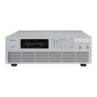
Chroma 62000H Series Operating & Programming Manual (236 pages)
Programmable DC Power Supply
Brand:
Chroma
| Category:
Power Supply
| Size: 6.09 MB
Table of Contents
Legal Notices
4
Safety Summary
9
Safety Symbols
10
Revision History
11
Table of Contents
13
1 Overview
17
Introduction
17
System Functions
17
Operation Mode
17
Protection
17
Output/Indication
18
Input Control Signals
18
Measuring & Editing
18
Specifications
18
Other Specifications
20
Function Keys
26
Front Panel
26
Rear Panel
28
2 Installation
31
Checking the Package
31
Maintenance & Cleaning
32
Preparation for Use
32
Normal Environment Conditions
33
Requirements of Input Power
33
Ratings
33
Input Connection
33
Remote Sensing
36
Correct Connection
36
Reverse Connection of Remote Sensing Wire Polarity
37
Output Connection
37
Rear Panel Output
37
Specification of Connecting Wire
40
Specification of Parallel Capacitance
40
Installing the Handle (62150H for Example)
41
Power on Procedure
41
3 Manual Operation
43
Introduction
43
Setting Voltage & Current
43
Setting Configuration
44
System Setup
47
Apg
47
Buzzer
52
Power on Status
52
Output Setup
54
Voltage Limit Setting
55
Current Limit Setting
56
Voltage Slew Rate
57
Current Slew Rate Setting
58
Setting DC_ON
59
Setting IV CURVE Parameters
60
Series/Parallel
63
Connecting Series/Parallel Output Cable
64
Assembling Series/Parallel Communication Interface
64
Setting Series/Parallel Operation Mode
67
Setting Series Parameters
73
Setting Parallel Parameters
74
Setting Procedure for APG in Series or Parallel
76
Display
78
Brightness
78
Display Selection
79
Reading Average Times
81
Protection
82
OVP Protection
82
OCP Protection
83
OPP Protection
84
Remote Inhibit
85
Safety Int.lock
87
External On/Off
89
Foldback
90
Otp
92
Ac Fault
93
3.3.5.10 SENSE FAULT Protection
93
3.3.5.11 FANLOCK Protection
94
3.3.5.12 D/D FAULT Protection
95
3.3.5.13 CURR. SHARING ERR Protection
95
3.3.5.14 FPGA UPDATE! Protection
96
3.3.5.15 C/S CABLE ERR. Protection
97
3.3.5.16 MATCH Warning
98
Factory Setting
98
Calibration
99
Voltage Output & Measurement Calibration
102
Current Measurement Calibration
104
Current Output (PROG.) Calibration
108
APG Voltage Calibration
111
APG Current Calibration
114
Voltage Output & Measurement Calibration (62020H-150S Only)
117
IV Voltage Output & Measurement Calibration (62020H-150S Only)
117
Current Calibration (62020H-150S Only)
119
Remote Setup
123
Gpib Address
123
Ethernet
123
Rs232/Rs485
125
Baudrate
126
Rs485 Addr
126
Rs485 Terminator
127
Rs485 Parser
127
Output Mode
128
CV/CC Mode
129
Sas Mode
131
En50530 Mode
135
Sandia Mode
136
Error Message
138
4 Program Sequence
141
List Mode
141
Description of PROGRAM Settings
142
Setting EXT._TRIG PULL
143
Setting PROG no
143
Setting RUN COUNT
143
Setting PROG CHAIN
145
Setting CLEAR PROGRAM
148
Setting Sequence
149
Setting Sequence Number
150
Setting Sequence Type
150
Setting Time
154
Setting Voltage
154
Setting Voltage Slew Rate
154
Setting Current
154
Setting Current Slew Rate
155
Execution in LIST MODE
155
Running LIST MODE
155
Program List Mode Description
156
V_Step Mode
156
Setting V_STEP MODE
157
Setting END_VOLTAGE
158
Setting RUN_TIME
158
Execution of V_STEP MODE
159
Running V_STEP MODE
159
IV Program
160
Description of Program V_Step Mode
160
Setting IV-PROGRAM
161
Setting IV-Sequence
162
Setting Sequence Number
162
Setting IV-FILE Number
163
Setting Sequence Type
163
Setting Time
164
Execution of IV PROGRAM
165
Running IV PROGRAM
165
IV Program Main Screen
166
5 Remote Operation
167
Overview
167
USB Interface
167
Connecting RS-232C
167
Connecting RS-485
168
Ethernet Remote Control
169
Selecting the LAN to be Connected
170
Setting IP, Subnet Mask & Gateway
172
Confirming Network Connected Successfully
178
Communicating with the Instrument
179
GPIB Function of 62000H Series
184
Introduction to Programming
184
Conventions
185
Numerical Data Formats
185
Boolean Data Format
185
Character Data Format
185
Basic Definition
186
Command Tree Structure
186
Program Headers
186
Common Command and Query Headers
186
Instrument-Controlled Headers
186
Program Header Separator (:)
186
Program Message
186
Program Message Unit
187
Program Message Unit Separator (;)
187
Program Message Terminator (<PMT>)
187
Traversal of the Command Tree
187
Execution Order
187
Commands of DC Power Supply
188
Common Command Syntax
188
Specific Commands for 62000H Series
192
ABORT Subsystem
192
CONFIGURE Subsystem
192
SOURCE Subsystem
198
FETCH Subsystem
201
MEASURE Subsystem
202
PROGRAM Subsystem
203
IV Subsystem
208
SAS Subsystem
212
OUTPUT Subsystem
215
5.6.2.10 SYSTEM Subsystem
217
6 Theory of Operation
219
Overview
219
Function Description
221
I/P (PFC) Stage
221
Auxiliary Power
222
Output Stage
222
Digital Circuit
222
7 ETHERNET Functions (62020H-150S Only)
223
Usage of Web Page
223
Home Page (Index.html)
223
Configuration Page
224
Soft Panel
226
Scpi
227
Remarks
227
62020H-150S ETHERNET Simple Operation
228
ETHERNET SETUP Page
228
Power Indicator & MAC Address Display
229
LAN Configuration Initialize (LCI) Function
229
IP Settings
230
Status Indicator
230
8 Self Test & Troubleshooting
231
Overview
231
Troubleshooting
231
Appendix Aapg & System Status Pin Assignment
233
Appendix B List of Protection
235
Advertisement
Chroma 62000H Series Operating & Programming Manual (238 pages)
Programmable DC Power Supply with Solar Array Simulation
Brand:
Chroma
| Category:
Power Supply
| Size: 7.7 MB
Table of Contents
Table of Contents
19
1 Overview
23
Introduction
23
System Functions
23
Operating Modes
23
Protection
23
Output/Indication
24
Input Control Signals
24
Measuring & Editing
24
Specifications
24
Other Specifications
26
Function Keys
32
Front Panel
32
Rear Panel
34
2 Installation
37
Checking the Package
37
Maintenance & Cleaning
38
Preparation for Use
38
Normal Environment Conditions
39
Input Power Requirements
39
Ratings
39
Input Connections
39
Remote Sensing
41
Correct Connection
41
Reverse Connection of Remote Sensing Wire Polarity
43
Output Connection
43
Rear Panel Output
43
Connecting Wire Specifications
45
Parallel Capacitance Specifications
46
Installing the Handle (62150H for Example)
46
Power-On Procedure
47
3 Manual Operation
49
Introduction
49
Setting Voltage & Current
49
Setting Configuration
50
System Setup
53
Apg
53
Buzzer
58
Power on Status
58
Output Setup
60
Voltage Limit Setting
61
Current Limit Setting
62
Voltage Slew Rate
63
Current Slew Rate Setting
64
Setting DC_ON
65
Setting IV CURVE Parameters
66
Series/Parallel
69
Connecting Series/Parallel Output Cables
70
Assembling Series/Parallel Communication Interface
70
Setting Series/Parallel Operation Mode
73
Setting Series Parameters
78
Setting Parallel Parameters
80
Setting Procedure for APG in Series or Parallel
82
Display
84
Brightness
84
Display Selection
85
Reading Average Times
87
Protection
88
OVP Protection
88
OCP Protection
89
OPP Protection
90
Remote Inhibit
91
Safety Int.lock
93
External On/Off
95
Foldback
96
Otp
98
Ac Fault
99
3.3.5.10 SENSE FAULT Protection
99
3.3.5.11 FANLOCK Protection
100
3.3.5.12 D/D FAULT Protection
101
3.3.5.13 CURR. SHARING ERR Protection
101
3.3.5.14 FPGA UPDATE! Protection
102
3.3.5.15 C/S CABLE ERR. Protection
103
3.3.5.16 MATCH Warning
104
Factory Setting
104
Calibration
106
Voltage Output & Measurement Calibration
108
Current Measurement Calibration
110
Current Output (PROG.) Calibration
113
APG Voltage Calibration
117
APG Current Calibration
120
Voltage Output & Measurement Calibration (62020H-150S Only)
122
Current Calibration (62020H-150S Only)
125
Remote Setup
128
Gpib Address
128
Ethernet
128
Rs232/Rs485
130
Baudrate
131
Rs485 Addr
131
Rs485 Terminator
132
Rs485 Parser
132
Output Mode
133
CV/CC Mode
134
Sas Mode
136
En50530 Mode
140
Sandia Mode
141
Error Message
143
4 Program Sequence
145
List Mode
145
Description of PROGRAM Settings
146
Setting EXT._TRIG PULL
147
Setting PROG no
147
Setting RUN COUNT
147
Setting PROG CHAIN
149
Setting CLEAR PROGRAM
152
Setting Sequence
153
Setting Sequence Number
154
Setting Sequence Type
154
Setting Time
158
Setting Voltage
158
4.1.2.5 Setting Voltage Slew Rate
158
Setting Current
158
Setting Current Slew Rate
159
Execution in LIST MODE
159
Running LIST MODE
159
Program List Mode Description
160
V_Step Mode
160
Setting END_VOLTAGE
162
Setting RUN_TIME
162
Execution of V_STEP MODE
163
Running V_STEP MODE
163
IV Program
164
Setting IV-PROGRAM
165
Setting IV-Sequence
166
Setting Sequence Number
166
Setting IV-FILE Number
167
Setting Sequence Type
167
Setting Time
168
Execution of IV PROGRAM
169
Running IV PROGRAM
169
IV Program Main Screen
170
5 Remote Operation
171
Overview
171
USB Interface
171
Connecting RS-232C
171
Ethernet Remote Control
173
Selecting the LAN to be Connected
174
Setting IP, Subnet Mask & Gateway
176
Confirming Network Connected Successfully
181
Communicating with the Instrument
183
GPIB Function of 62000H Series
189
Introduction to Programming
189
Conventions
190
Numerical Data Formats
190
Boolean Data Format
190
Character Data Format
190
Basic Definition
191
Command Tree Structure
191
Program Headers
191
Common Command and Query Headers
191
Instrument-Controlled Headers
191
Program Header Separator (:)
191
Program Message
191
Program Message Unit
192
Program Message Unit Separator (;)
192
Program Message Terminator (<PMT>)
192
Traversal of the Command Tree
192
Execution Order
192
DC Power Supply Commands
193
Common Command Syntax
193
Specific Commands for 62000H Series
197
ABORT Subsystem
197
CONFIGURE Subsystem
197
SOURCE Subsystem
203
FETCH Subsystem
206
MEASURE Subsystem
207
PROGRAM Subsystem
207
IV Subsystem
212
SAS Subsystem
216
OUTPUT Subsystem
219
5.6.2.10 SYSTEM Subsystem
220
6 Theory of Operation
221
Overview
221
Function Description
223
I/P (PFC) Stage
223
Auxiliary Power
224
Output Stage
224
Digital Circuit
224
7 ETHERNET Functions (62020H-150S Only)
225
Usage of Web Page
225
Home Page (Index.html)
225
Configuration Page
226
Soft Panel
228
Scpi
229
Remarks
229
62020H-150S ETHERNET Simple Operation
230
ETHERNET SETUP Page
230
Power Indicator & MAC Address Display
231
LAN Configuration Initialize (LCI) Function
231
IP Settings
232
Status Indicator
232
8 Self Test & Troubleshooting
233
Overview
233
Troubleshooting
233
Appendix Aapg & System Status Pin Assignment
235
Appendix B List of Protection Messages
237
Chroma 62000H Series Operating & Programming Manual (168 pages)
Programmable DC Power Supply
Brand:
Chroma
| Category:
Power Supply
| Size: 4.48 MB
Table of Contents
Table of Contents
13
1 Overview
17
Introduction
17
System Functions
17
Operation Mode
17
Protection
17
Output/Indication
18
Input Control Signals
18
Measuring & Editing
18
Specifications
18
Other Specifications
22
Function Keys
26
Front Panel
26
Rear Panel
29
2 Installation
31
Checking the Package
31
Maintenance & Cleaning
31
Preparation for Use
31
Normal Environment Conditions
32
Requirements of Input Power
32
Ratings
32
Input Connection
33
Remote Sensing
35
Correct Connection
35
Disconnecting Remote Sensing Wire
36
Reverse Connection of Remote Sensing Wire Polarity
36
Output Connection
36
Rear Panel Output
36
Specification of Connecting Wire
39
Specification of Parallel Capacitance
39
Installing the Handle
40
Power on Procedure
40
3 Manual Operation
43
Introduction
43
Setting Voltage & Current
43
Setting Configuration
44
System Setup
47
Apg
47
Buzzer
52
Power on Status
52
Output Setup
54
Voltage Limit Setting
55
Current Limit Setting
56
Voltage Slew Rate
57
Current Slew Rate Setting
58
Setting DC_ON
59
Series/Parallel
60
Connecting Series/Parallel Output Cable
61
Assembling Series/Parallel Communication Interface
61
Setting Series/Parallel Operation Mode
63
Setting Series Parameters
68
Setting Parallel Parameters
70
Setting Procedure for APG in Series or Parallel
72
Display
74
Brightness
74
Display Selection
75
Reading Average Times
77
Protection
78
OVP Protection
79
OCP Protection
80
OPP Protection
81
Remote Inhibit
82
Safety Int.lock
83
External On/Off
85
Foldback
86
Otp
88
Ac Fault
89
SENSE FAULT Protection
89
FANLOCK Protection
90
D/D FAULT Protection
91
Factory Setting
91
Calibration
92
Voltage Output & Measurement Calibration
93
Current Measurement Calibration
95
Current Output (PROG.) Calibration
99
APG Voltage Calibration
102
APG Current Calibration
105
Remote Setup
108
Gpib Address
108
Ethernet
108
Rs232/Rs485
110
Baudrate
110
Rs485 Addr
111
Rs485 Terminator
112
4 Program Sequence
113
List Mode
113
Description of PROGRAM Settings
114
Setting EXT._TRIG PULL
115
Setting PROG no
115
Setting RUN COUNT
115
Setting PROG CHAIN
117
Setting CLEAR PROGRAM
120
Setting Sequence
121
Setting Sequence Number
122
Setting Sequence Type
122
Setting Time
126
Setting Voltage
126
Setting Voltage Slew Rate
126
Setting Current
126
Setting Current Slew Rate
127
Execution in LIST MODE
127
Running LIST MODE
127
Program List Mode Description
128
V_Step Mode
128
Setting V_STEP MODE
129
Setting START_VOLTAGE
129
Setting END_VOLTAGE
130
Setting RUN_TIME
130
Execution of V_STEP MODE
131
Running V_STEP MODE
131
Description of Program V_Step Mode
132
5 Remote Operation
133
Overview
133
USB Interface
133
Connecting RS-232C
133
Connecting RS-485
134
Ethernet Remote Control
135
GPIB Function of 62000H Series
135
Introduction to Programming
135
Conventions
136
Numerical Data Formats
136
Boolean Data Format
137
Character Data Format
137
Basic Definition
137
Command Tree Structure
137
Program Headers
137
Common Command and Query Headers
137
Instrument-Controlled Headers
137
Program Header Separator (:)
138
Program Message
138
Program Message Unit
138
Traversal of the Command Tree
138
Execution Order
139
Commands of DC Power Supply
139
Common Command Syntax
139
Specific Commands for 62000H Series
143
ABORT Subsystem
143
CONFIGURE Subsystem
143
SOURCE Subsystem
148
FETCH Subsystem
151
MEASURE Subsystem
152
PROGRAM Subsystem
152
SYSTEM Subsystem
157
6 Theory of Operation
159
Overview
159
Function Description
161
I/P (PFC) Stage
161
Auxiliary Power
162
Output Stage
162
Digital Circuit
162
7 Self Test & Troubleshooting
163
Overview
163
Troubleshooting
163
Appendix A APG & System Status Pin Assignment
165
Advertisement
Advertisement
Related Products
Chroma 62000P Series
Chroma 62006P-100-25
Chroma 62000D Series
Chroma 62000L Series
Chroma 62000B Series
Chroma 62000B-3-1
Chroma 62000B-6-1
Chroma 62015B-24-62
Chroma 62015B-80-18
Chroma 62015L-60-6
Chroma Categories
Lighting Equipment
DJ Equipment
Power Supply
Test Equipment
Light Fixture
More Chroma Manuals
Login
Sign In
OR
Sign in with Facebook
Sign in with Google
Upload manual
Upload from disk
Upload from URL