Sign In
Upload
Manuals
Brands
Burkert Manuals
Control Unit
8630
Burkert 8630 Manuals
Manuals and User Guides for Burkert 8630. We have
2
Burkert 8630 manuals available for free PDF download: Operating Instructions Manual
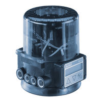
Burkert 8630 Operating Instructions Manual (192 pages)
TOP Control Continuous
Brand:
Burkert
| Category:
Valve Positioners
| Size: 3.29 MB
Table of Contents
Overall Operating Instructions Top Control Continuous 8630
3
Table of Contents
3
Symbols
12
Intended Use
12
Safety Notes
12
Protection from Damage by Electrostatic Charging
13
Scope of Delivery
13
Warranty Conditions
13
Master Code
14
Transport, Storage
14
Disposal
14
System Description
15
Valve Types
16
Characteristics of the Valve Types
17
Construction of TOP Control Continuous
18
Illustrations (Cover Removed)
18
Design Features
19
Functional Diagram as a Positioner with Single-Acting Actuator
20
Operation as a Positioner
21
Schematic Representation of Positioning Control
22
Characteristics of the Positioner Software
23
Operation as a Process Controller (Option)
24
Example of Process Control: TOP Control Continuous with Sensor
24
Schematic Representation of Process Control
25
Characteristics of the Process Controller Software
26
Operation as a Flow Rate Controller (Option)
27
Characteristics of the Flow Rate Controller Software
27
Schematic Representation of Process Control with Flow Rate Controller
28
Interfaces of the TOP Control Continuous in the Multipole Variant
29
Interfaces of the TOP Control Continuous in the Variants with Cable Bushings
30
Technical Data
31
Safety Settings on Failure of Auxiliary Electrical or Pneumatic Energy
31
Factory Settings on the TOP Control Continuous
32
Data of the TOP Control Continuous
33
Fluidic Installation
36
Electrical Installation - Multipole Connector
37
Electrical Installation - Connection Terminals for Cable Bushings
38
Basic Settings of the TOP Control Continuous
39
Settings in the Menu Items
40
Manual Opening and Closing of the Valve Actuator in the MANUAL Mode
41
Installation
43
Installation of the Valve
44
Turning the TOP Control Continuous
44
Procedure
44
Fluidic Connection of the TOP Control Continuous
45
Electrical Connection - Multipole Connectors
46
Marking of the Multipole Plugs or Sockets and the Contacts
46
Output Signals for SPS (Circular Plug M16)
47
Operating Voltage (Circular Plug M 12)
47
Inductive Proximity Switches (Circular Socket M 8)
47
Process Value (Circular Plug M 8)
48
Option: with Temperature Sensor Input (3 Circular Plugs M8)
48
Electrical Connection - Terminals for Cable Bushing
49
Connection PCB of the TOP Control Continuous with Screw Terminals and Jumpers
49
Terminal Configuration with Cable Bushings
49
Electrical Connection - Terminals with Cable Bushing
49
Choice of Binary Outputs or Process Value Input
50
Setting the Inductive Proximity Switches (Option)
52
Opening the Housing of the TOP Control Continuous
52
Positioning the Inductive Proximity Switches
52
Operation and Controller Function
53
Operation and Controller Functions
53
Operating and Display Elements
54
Operating Levels
54
Commissioning and Set-Up as a Positioner
55
Procedure for Specifying the Basic Settings
55
Main Menu for the Settings on Commissioning
56
Description of the Procedure
57
Configuring the Supplementary Functions
61
Keys in the Configuration Level
61
Configuration Menu
61
Supplementary Functions
64
Operating the Process
88
Changeover between Operating Modes
88
Operating Mode AUTOMATIC
89
Meaning of the Keys in the AUTOMATIC Mode
89
Display of the AUTOMATIC Mode
89
Operating Mode MANUAL
90
Meaning of the Keys in the MANUAL Mode
90
Display of the MANUAL Mode
90
Operating the Process Controller
91
Factory Settings on the Process Controller
92
Setting up a Process Control System
92
Self-Parametrization for Positioner - X.TUNE
93
Supplementary Function P.CONTRL
93
Self-Parametrization of the Positioner - X.TUNE
93
Basic Settings of the Function P.CONTRL
94
P.Q'LIN - Starting the Routine for Linearization of the Process Curve
107
Display During Call-Up and Execution of the Routine
107
P.CO TUNE - Self-Optimization of the Process Controller (Process Tune)
108
P.CO LEAK - Leakage Characteristic for Flow Rate Control
112
Operating the Process
114
Changeover between the Operating Modes
114
Operating Mode AUTOMATIC
115
Meaning of the Keys
115
Displays
115
Operating Structure and Procedures
115
Operating Mode MANUAL
116
Meaning of the Keys
116
Displays
117
Operating Structure and Procedures
117
Manually Changing the Process Setpoint
116
Profibus Dp
119
General Notes
120
Safety Settings on Bus Failure
120
Technical Data
120
Electrical Connections
121
Connection with One Plugged Bus Connector
121
Connection with 2 Plugged Bus Connectors
122
Operating Voltage (Circular Plug M12)
122
Bus Connection (Circular Socket M12)
122
Inductive Proximity Switches (Circular Socket M8)
123
Process Value (Circular Plug M8)
123
Termination Connection for PROFIBUS Systems
124
Interfaces
121
Settings on the TOP Control Continuous
125
Explanation of the Menu Items
126
Functional Deviations from the Standard Version
126
Configuration in the Profibus DP Master
127
Configuration of the Process Values
127
Bus Status Display
129
Example 1 with COM-Profibus V3.3
130
Example for a Positioner
130
Example 2 with COM-Profibus V3.3
133
Example for a Process Controller
133
Device-Net
135
Device Net
135
General Notes
136
Explanation of Terms
136
Technical Data
137
Safety Settings on Bus Failure
137
Interfaces
138
Electrical Connection
138
Operating Voltage (4-Pole M12 Circular Plug)
139
Bus Connection (4-Pole M12 Circular Plug)
139
Inductive Proximity Switches (4-Pole M8 Circular Socket)
139
Process Value (Circular Plug M8)
139
Termination Connection for Devicenet Systems
140
Net Topology of a Devicenet System
140
Settings on the TOP Control Continuous
141
Explanation of the Menu Items in the Program Run-Off Schematic
141
Settings in the Main Menu
142
Setting in the Main Menu
142
Configuring the Process Data
143
Static Input Assemblies
143
Static Output Assemblies
145
Bus Status Display
146
Configuration Example 1
147
Installation of the EDS File
147
Address Allocation
147
Offline Parametrization of the Device
148
Online Parametrization of the Device
149
Configuration Example 2
150
Setting up the Process Map (Mapping)
151
Maintenance
154
Process Controller
155
Maintenance
156
Other Malfunctions
158
General Rules (Appendix)
159
Selection Criteria for Continuous Valves
160
Characteristics of PID Controllers
162
P Component
162
I Component
163
D Component
164
Superimposing the P, I and D Components
165
Function of a Real PID Controller
166
Rules for Setting PID Controllers
167
Setting Rules of Ziegler and Nichols (Oscillation Method)
167
Setting Rules of Chien, Hrones and Reswick (Controller Output Step Method)
168
Operating Structure
171
Operating Structure of the TOP Control Continuous
172
Table for Noting Your Settings on the Positioner
180
Tables for Noting Your Settings on the Process Controller
182
Advertisement
Burkert 8630 Operating Instructions Manual (136 pages)
positioner
Brand:
Burkert
| Category:
Control Unit
| Size: 3.49 MB
Table of Contents
Deutsch
2
Table of Contents
2
1 Allgemeine Hinweise
4
Darstellungsmittel
4
Sicherheitshinweise
4
Schutz gegen Beschädigung durch Elektrostatische Aufladung
4
Lieferumfang
5
Garantiebestimmungen
5
2 Systemkonfiguration
6
3 Beschreibung des Top Control
8
Aufbau
8
Funktion
10
Betrieb des Positioners als Stellungsregler
11
Betrieb des Positioners als Prozeßregler
12
Varianten des Topcontrol
13
Eigenschaften der Software
14
Technische Daten
15
Sicherheitsstellungen nach Ausfall der Elektrischen Bzw. Pneumatischen Hilfsenergie
15
Daten des Positioners Topcontrol
16
4 Erste Inbetriebnahme
17
Fluidische Installation
17
Elektrische Installation
17
Grundeinstellungen
18
5 Installation
21
Fluidischer Anschluß
21
Fluidischer Anschluß des Ventils
21
Fluidischer Anschluß des Positioners
21
Elektrischer Anschluß
21
Multipolstecker
22
Anschlußklemmen für PG-Verschraubungen
24
Einstellen der Initiatoren (Option)
26
6 Bedienung
27
Bedien- und Anzeigeelemente
27
Bedienebenen
27
Inbetriebnahme und Einrichten als Stellungsregler
28
Vorgehensweise zum Festlegen der Grundeinstellungen
28
Konfigurieren der Zusatzfunktionen
32
Konfiguriermenü
32
8 Anhang
33
Input
33
Addfunct
33
End
33
X.tune
33
Charact
36
Dir.CMD
37
Cutoff
37
Dir.act
38
Spltrng
39
X.limit
40
X.time
40
X.control
41
P.control
42
P.co - Dbnd
42
P.co - para
43
P.co - Setp
43
P.co - Inp
43
P.co Scal
44
Code
47
Bin-In
48
Cal.user
50
Setfact
53
Einrichten einer Prozeßregelung
54
Prozeßbedienen
55
Einstellregeln für PID-Regler
66
English
69
1 General Information
71
Symbols
71
Safety Information
71
Important for Handling
71
Scope of Delivery
72
Warranty Conditions
72
2 System Configuration
73
3 Description of the Top Control
75
Construction
75
Function
77
Working of the Positioner as Position Controller
78
Using the Positioner as a Process Controller
79
Top Control Variants
80
Software Characteristics
81
Technical Characteristics
82
Safety Positions According to Electrical and Pneumatic Power Supplys
82
Factory Settings of the Topcontrol Positioners
82
Characteristics of the Topcontrol Positioner
83
4 Initial Commissioning
84
Pneumatic Connection
84
Electrical Connection
84
Basic Configuration
85
5 Installation
88
Pneumatic Connection
88
Pneumatic Connection of the Valve
88
Pneumatic Connection of the Positioner
88
Electrical Connection
88
Multipole Connection
89
Cable Gland Connection
91
Installation of the Position Switches (Option)
93
6 Operation
94
Control and Display Elements
94
Operating Levels
94
Commissioning as a Position Controller
95
Operating Mode for Basic Configuration
95
Configuration of the Additional Functions
99
Configuration Menu
99
Additional Functions
101
8 Appendix
103
Input
103
Spltrng
106
X.limit
107
X.time
107
X.control
108
P.control
109
P.co - Dbnd
109
P.co - para
110
P.co - Setp
110
P.co - Inp
110
P.co Scal
111
Code
114
Bin-In
115
Cal.user
117
Setfact
120
Advertisement
Related Products
Burkert 8690
Burkert 8691
Burkert 8697
Burkert 8691 REV.2
Burkert 8647 AirLINE SP
Burkert 8653 AirLINE Field
Burkert 8631
Burkert 8650
Burkert 8695 Series
Burkert 8835
Burkert Categories
Control Unit
Controller
Measuring Instruments
Transmitter
Accessories
More Burkert Manuals
Login
Sign In
OR
Sign in with Facebook
Sign in with Google
Upload manual
Upload from disk
Upload from URL