Sign In
Upload
Manuals
Brands
Burkert Manuals
Control Unit
8695 Series
Burkert 8695 Series Manuals
Manuals and User Guides for Burkert 8695 Series. We have
3
Burkert 8695 Series manuals available for free PDF download: Operating Instructions Manual, Quick Start Manual
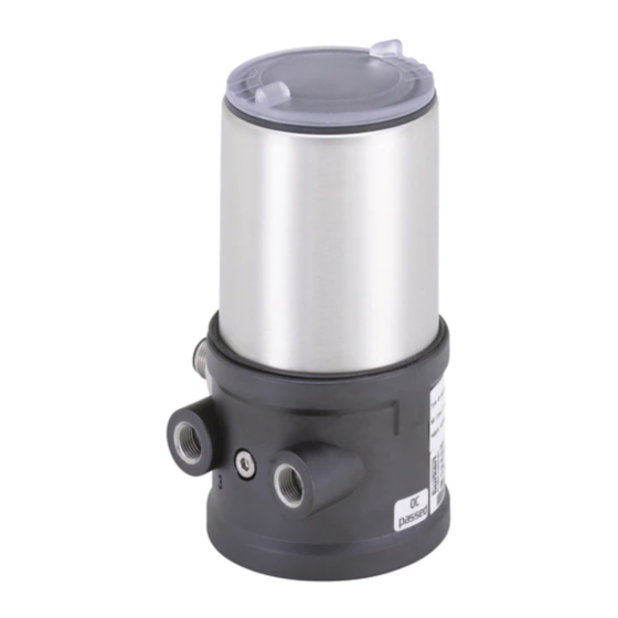
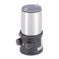
Burkert 8695 Series Operating Instructions Manual (67 pages)
Brand:
Burkert
| Category:
Control Unit
| Size: 2.58 MB
Table of Contents
Table of Contents
3
1 Operating Instructions
7
Symbols
7
Definition of Term / Abbreviation
7
2 Authorized Use
8
Restrictions
8
3 Basic Safety Instructions
9
4 General Information
10
Contact Address
10
Warranty
10
Trademarks
10
Information on the Internet
10
5 System Description
11
Structure and Function
11
Control Head for Integrated Installation on 21Xx Series (Element)
11
Model for Control of Process Valves Belonging to the 20Xx Series (Classic)
12
6 Technical Data
13
Conformity
13
Standards
13
Licenses
13
Operating Conditions
13
Mechanical Data
13
Type Labels
14
Type Label Standard
14
UL Type Label
14
UL Additional Label
15
Pneumatic Data
15
Electrical Data
16
Electrical Data Without Bus Control 24 V DC
16
Electrical Data with AS-Interface Bus Control
16
Electrical Data with Devicenet Bus Control
16
7 Installation
17
Safety Instructions
17
Installation of the Control Head Type 8695 on Process Valves of Series 21Xx (Element)
17
Installation of the Control Head Type 8695 on Process Valves of Series 20Xx (Classic)
22
Rotating the Actuator Module on Process Valves of Series 2100, 2101, 2000 and 2012
26
Rotating the Control Head for Process Valves Belonging to Series 20Xx
28
Manual Actuation of the Actuator Via Pilot Valves
29
8 Pneumatic Installation
30
9 Electrical Installation 24 V DC
32
Safety Instructions
32
Electrical Installation
33
Teach Function (Calibrating the End Position)
34
Display and Control Elements 24 V DC
36
Status LED Yellow
36
Valve LED Yellow
36
End Position LED Green and Yellow
37
Jumper Function
37
Change Assignment of the End Position Leds
37
10 As-Interface Installation
39
AS-Interface Connection
39
Technical Data for AS-Interface Pcbs
39
Programming Data
39
Electrical Installation AS-Interface
40
Safety Instructions
40
Connection with Circular Plug-In Connector M12 X 1, 4-Pole, Male
40
Connection with Multi-Pole Cable and Ribbon Cable Terminal
41
Teach Function (Calibrating the End Position)
42
Display and Control Elements AS-Interface
44
Status LED Yellow
44
Valve LED Yellow
44
Bus LED Red and Green
45
End Position Leds
45
Jumper Function
46
Change Assignment of the End Position Leds
46
11 Devicenet Installation
48
Definition
48
Technical Data
48
Maximum Line Lengths
48
Total Line Length According to Devicenet Specification
48
Drop Line Length
49
Safety Setting if the Bus Fails
49
Interfaces
49
Electrical Connection Devicenet
49
Safety Instructions
49
Display and Control Elements Devicenet
50
Bus Connection (Circular Connector M12 X 1, 5-Pole, Male)
50
Terminating Circuit for Devicenet Systems
50
Network Topology of a Devicenet System
51
Configuring the Control Head
51
DIP Switches
51
11.10 Configuration of the Process Data
53
Configuration of the Safety Position of Pilot Valves for Bus Error
54
Teach Function (Calibrating the End Position)
54
11.12.1 Starting the Teach Function
57
11.13 Display Elements Devicenet
58
11.13.1 Device Status LED and Bus LED
59
11.13.2 End Position Leds
60
11.13.3 Status LED Yellow
60
11.13.4 Valve LED Yellow
60
13 Maintenance
61
12 Safety Positions
61
14 Disassembly
62
Safety Instructions
62
Disassembly the Control Head
62
15 Accessories
64
Communications Software
64
USB Interface
64
Download
64
16 Packaging and Transport
65
17 Storage
65
18 Disposal
65
Advertisement
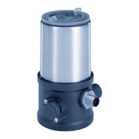
Burkert 8695 Series Operating Instructions Manual (68 pages)
Control Head
Brand:
Burkert
| Category:
Industrial Equipment
| Size: 1.78 MB
Table of Contents
Table of Contents
3
About These Instructions
7
Symbols
7
Definition of Terms
7
Intended Use
8
Basic Safety Instructions
9
General Information
10
Contact Address
10
Warranty
10
Trademarks
10
Information on the Internet
10
System Description
11
Structure and Function
11
Control Head for Integrated Installation on 21Xx Series (ELEMENT)
11
Model for Control of Process Valves Belonging to the 20Xx Series (CLASSIC)
12
Technical Data
13
Standards and Directives
13
Licenses
13
Operating Conditions
13
Mechanical Data
14
Type Labels
14
Type Label Standard
14
UL Type Label
14
UL Additional Label
15
Pneumatic Data
15
Electrical Data
16
Electrical Data Without Field Bus Communication
16
Electrical Data, IO-Link
16
Electrical Data, Büs
17
Electrical Data, AS-Interface
17
Communication
18
IO-Link
18
Installation
19
Safety Instructions
19
Installation of the Control Head Type 8695 on Process Valves of Series 21Xx (ELEMENT)
19
Installation of the Control Head Type 8695 on Process Valves of Series 20Xx (CLASSIC)
24
Rotating the Actuator Module on Process Valves of Series 2100, 2101, 2000 and 2012
28
Rotating the Control Head for Process Valves Belonging to Series 20Xx
30
Pneumatic Installation
31
Electrical Installation
33
Safety Instructions
33
Electrical Installation, Without Fieldbus Communication
34
Electrical Installation, IO-Link Port Class B and Port Class a
35
Electrical Installation, Büs
35
Electrical Installation, AS-Interface
36
Connection with Circular Plug-In Connector M12 X 1, 4-Pin
36
Connection with Multi-Pole Cable and Ribbon Cable Terminal
37
Start-Up
38
Invert Process Valve Direction
38
Teach Function: Determine End Positions And Save These, Rev.3
40
Automatic Teach Function
40
Manual Teach Function
42
Teach-In-Operation Function
44
Setting With Bürkert Communicator
45
Connecting IO-Link Device with Bürkert Communicator
45
IO-Link
47
Information, IO-Link
47
Configuration Of The Fieldbus
47
Büs
47
Information, Büs
47
AS-Interface
48
Certification
48
Programming Data
48
Control and Display Elements
49
Operating State
50
Functions Of The Operating And Display Elements
51
Status Indicator
54
Description Of The Led Modes
55
Valve Mode
55
Valve Mode and Error
55
Valve Mode and Warnings
56
NAMUR Mode
57
Fixed Colour
57
LED off
57
Manual Actuation Of The Actuator With Pilot Valve
58
Setting The Led Mode, Status Indicator
60
Safety End Positions
61
Maintenance
61
Disassembly
62
Safety Instructions
62
Disassembly The Control Head
62
Accessories
64
Communications Software
64
Packaging and Transport
65
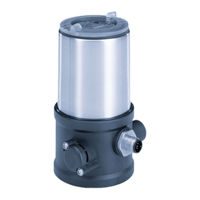
Burkert 8695 Series Quick Start Manual (38 pages)
REV.3 Control Head
Brand:
Burkert
| Category:
Control Unit
| Size: 1.58 MB
Table of Contents
Table of Contents
3
About These Instructions
4
Symbols
4
Definition of Term
4
Intended Use
5
Basic Safety Instructions
5
General Information
6
Contact Address
6
Warranty
6
Information on the Internet
6
System Description
7
Structure and Function
7
Technical Data
8
Standards and Directives
8
Approvals
8
Operating Conditions
8
Mechanical Data
9
Type Labels
9
Pneumatic Data
10
Electrical Data
10
Communication
12
Installation
12
Safety Instructions
12
Installation of the Control Head on Process Valves of Series 21Xx
13
Installation of the Control Head on Process Valves of Series 20Xx
14
Manual Actuation of the Actuator Via Pilot Valve
16
Pneumatic Installation
17
Electrical Installation
18
Safety Instructions
18
Electrical Installation, Without Fieldbus Communication
18
Electrical Installation, IO-Link, Port Class B and Port Class a
19
Electrical Installation, Büs
19
Electrical Installation, AS-Interface
20
Start-Up
21
Invert Process Valve Direction
21
Teach Function: Determine End Positions and Save These, REV.3
23
Setting The Device With Bürkert Communicator
27
10.4 IO-Link
28
10.5 Büs
28
10.6 AS-Interface
28
Control and Display Elements
29
Open And Close The Device
30
Operating State
30
Functions Of The Operating And Display Elements
30
Safety End Positions
35
Accessories
36
Communications Software
36
Packaging, Transport, Storage
36
Advertisement
Advertisement
Related Products
Burkert 8630
Burkert 8690
Burkert 8691
Burkert 8697
Burkert 8691 REV.2
Burkert 8647 AirLINE SP
Burkert 8653 AirLINE Field
Burkert 8631
Burkert 8650
Burkert 8840
Burkert Categories
Control Unit
Controller
Measuring Instruments
Transmitter
Accessories
More Burkert Manuals
Login
Sign In
OR
Sign in with Facebook
Sign in with Google
Upload manual
Upload from disk
Upload from URL