
Related Manuals for Burkert 8630


Summary of Contents for Burkert 8630
- Page 1 Operating Instructions Bedienungsanleitung Instructions de Service Type 8630 TOP Control Continuous...
- Page 2 We reserve the right to make technical changes without notice. Technische Änderungen vorbehalten. Sous resérve de modification techniques. © 2001 Bürkert Werke GmbH & Co KG. Operating Instructions 0507/11_EU-EN_00804575...
-
Page 3: Table Of Contents
ONTENTS Overall Operating Instructions TOP Control Continuous 8630 GENERAL NOTES Symbols ..................................................Intended use ................................................Safety notes ................................................Protection from damage by electrostatic charging ......................... Scope of delivery .............................................. Warranty conditions ............................................Master code ................................................Transport, storage ............................................Disposal .................................................. - Page 4 Manual opening and closing of the valve actuator in the MANUAL mode ................INSTALLATION Installation of the valve ..........................................Turning the TOP Control Continuous .................................. Procedure ................................................... Fluidic connection of the TOP Control Continuous ........................* Alternative chapters or functions depending on device configuration 2 - 8630...
- Page 5 Meaning of the keys in the AUTOMATIC mode ..............................Display of the AUTOMATIC mode ..................................... Operating mode MANUAL ........................................Meaning of the keys in the MANUAL mode ................................Display of the MANUAL mode ......................................* Alternative chapters or functions depending on device configuration 8630 - 3...
- Page 6 Safety settings on bus failure ......................................Interfaces ..................................................Electrical connections ..........................................Connection with one plugged bus connector ................................Connection with 2 plugged bus connectors ................................Operating voltage (circular plug M12) ..................................... Bus connection (circular socket M12) .................................... 4 - 8630...
- Page 7 Settings on the TOP Control Continuous ..............................Explanation of the menu items in the program run-off schematic ...................... Settings in the main menu ......................................... Configuring the process data ......................................Static input assemblies ..........................................Static output assemblies ..........................................8630 - 5...
- Page 8 ..................................Error messages on the LC display ..................................... Other malfunctions ............................................. MAINTENANCE AND ERROR CORRETION ON THE PROCESS CONTROLLER Maintenance ................................................Error messages and malfunctions ..................................Error messages on the LC display ..................................... Other malfunctions ............................................. Appendix 6 - 8630...
- Page 9 Operating structure of the TOP Control Continuous ........................TABLE FOR POSITIONER Table for noting your settings on the positioner ..........................TABLE FOR PROCESS CONTROLLER Tables for noting your settings on the process controller ..................... MASTER CODE Code number ................................................8630 - 7...
- Page 10 ONTENTS 8 - 8630...
- Page 11 ENERAL OTES GENERAL NOTES Symbols ....................................................Intended use ................................................Safety notes .................................................. Protection from damage by electrostatic charging ..........................Scope of delivery ..............................................Warranty conditions ............................................Master code .................................................. Transport, storage ..............................................Disposal ..................................................... 8630 - 9...
-
Page 12: Symbols
• Make sure that after an interruption to the electrical or pneumatic supply, the process starts up again in a well-defined, controlled manner! • On non-observance of these notes and unauthorized interference with the device, we will refuse all liability and the warranty on device and accessories will become void! 10 - 8630... -
Page 13: Protection From Damage By Electrostatic Charging
The warranty covers only faultless condition of the TOP Control Continuous and the attached valve with pneumatic actuation. No liability will be accepted for consequential damage of any kind that may arise from failure or malfunctioning of the device. 8630 - 11... -
Page 14: Master Code
If required, cut out this code and keep it separate from these operating instructions. Transport, storage ATTENTION! Transport and store the appliance in its original packing only. Disposal ATTENTION! When disponsing of the appliance, observe the national standards for refuse disposal. 12 - 8630... -
Page 15: System Description
Technical data ............................................... Safety settings on failure of auxiliary electrical or pneumatic energy ..............Factory settings on the TOP Control Continuous ..........................Data of the TOP Control Continuous .................................. Alternative chapters or functions depending on device configuration 8630 - 13... -
Page 16: Valve Types
Type 2655 Type 2730 Various process valves from the Bürkert range can be combined with the TOP Control to suit different applications. Y-, diaphragm or ball valves with control cones are suitable. 14 - 8630... -
Page 17: Characteristics Of The Valve Types
• contaminated, ab- • pure water • slightly aggressive hydraulic fluides rasive and aggressive media media • slightly aggressive • Salt solutions, lyes media (organic) • high purity or sterile media • Organic solvents • high viscosity media 8630 - 15... -
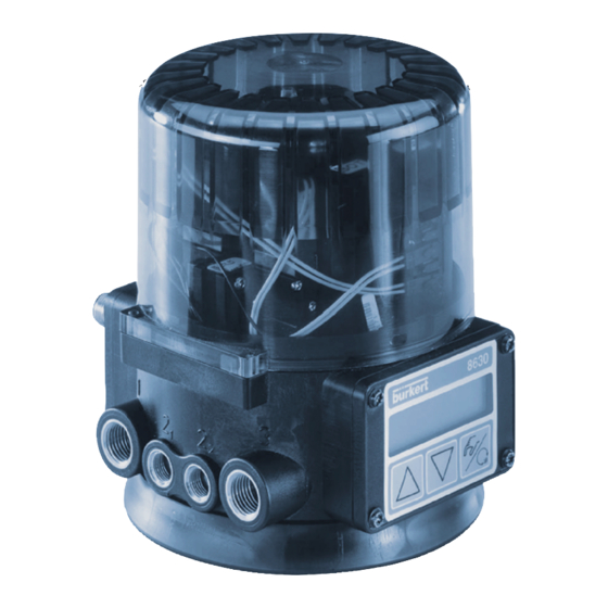
Page 18: Construction Of Top Control Continuous
Pressure supply port (marked: 1) Exhaust air ports Control ports (connected in the (marked 3) factory) Fixing screw for fixing the Electrical connection module, TOP Control Continuous here with multipole connectors on the drive Max. torque 1.2 Nm 16 - 8630... -
Page 19: Design Features
The housing of the TOP Control is protected by a pressure relief valve from excessive internal pressure, e.g. resulting from leaks. The cover may be secured against unauthorized opening with a lead seal or with a self-tapping screw. 8630 - 17... -
Page 20: Functional Diagram As A Positioner With Single-Acting Actuator
Positioning system 1: pressurizing valve Actual 2: exhaust valve position Positioning TOP Control Continuous system Compressed air Position supply sensor Exhaust air Pneumatic actuator (single-acting) Valve (actuator) Sensor Actual process value (flow rate, pressure, level, temperature etc.) 18 - 8630... -
Page 21: Operation As A Positioner
E1. In this way, the position of the actuator is altered until the control difference is zero. Z1 represents a disturbance. Valve opening Position setpoint Positioner Positioning Continious valve system Sole- noid Position control Wegmeßsystem Position sensor loop 8630 - 19... -
Page 22: Schematic Representation Of Positioning Control
YSTEM ESCRIPTION 20 - 8630... -
Page 23: Characteristics Of The Positioner Software
Hierarchical concept for simple operation with the following levels In this level your switch between automatic and manual Process operation operation. In this level you specify on commissioning certain basic Configuration functions and configure supplementary functions as needed. 8630 - 21... -
Page 24: Operation As A Process Controller (Option)
In this way, the position of the actuator is altered until the control difference is zero. Z2 represents a disturbance. Valve opening Positioner Positioning Continuous system Soleno- Valve id valves XPOS Position sensor Valve opening Process variable Process Process Process controller setpoint Transmitter 22 - 8630... -
Page 25: Schematic Representation Of Process Control
YSTEM ESCRIPTION 8630 - 23... -
Page 26: Characteristics Of The Process Controller Software
Hierarchical concept for simple operation with the following levels In this level your switch between automatic and manual Process operation operation. In this level you specify on commissioning certain basic Configuration functions and configure supplementary functions as needed. 24 - 8630... -
Page 27: Operation As A Flow Rate Controller (Option)
The diameter is entered in the operating menu. Characteristics of the flow rate controller software The flow rate controller offers the same functions as the process controller. 8630 - 25... -
Page 28: Schematic Representation Of Process Control With Flow Rate Controller
YSTEM ESCRIPTION 26 - 8630... -
Page 29: Interfaces Of The Top Control Continuous In The Multipole Variant
The standard process controller inputs (4 ... 20 mA, frequency, Pt 100) and the initiators cannot be used with this option. NOTE TOP Control Continuous Type 8630 is a 3-conductor device, i.e. the voltage supply (24 V DC) is separate from the setpoint signal. -
Page 30: Interfaces Of The Top Control Continuous In The Variants With Cable Bushings
Operating unit process setpoint input and two binary outputs is made by positioning the jumper. NOTE TOP Control Continuous Type 8630 is a 3-conductor device, i.e. the voltage supply (24 V DC) is separate from the setpoint signal. 28 - 8630... -
Page 31: Technical Data
Safety settings on failure of auxiliary electrical or pneumatic energy Actuator type Designation Safety position after failure of auxiliary energy Electrical Pneumatic Single-acting down down Single-acting Double-acting down / up undefined (depending on connection of control conductors) 8630 - 29... -
Page 32: Factory Settings On The Top Control Continuous
B.IN SPOS SPOS 000 NO UNIT M3/H TEMP DENS 1.293 DIAM 0025 P.CO TUNE D’ACT P.CO KV FACT CODE CODE 0000 NOTE The functions and factory settings shown in grey are valid for the optional flow rate control. 30 - 8630... -
Page 33: Data Of The Top Control Continuous
Protection class 3 to VDE 0580 Analog position feedback: max. current for voltage output 0 ... 5/10 V 10 mA max. burden 560 Ω for current output 0/4 ... 20 mA Inductive proximity switch current limitation 100 mA 8630 - 31... - Page 34 / min STP (for pressurizing and exhausting) - value acc. to definition on pressure drop from 7 to 6 bar abs.) Intrinsic air consumption with zero control output 0.0 l /min STP Connections G 1/4’’ internal thread G / NPT / RC 32 - 8630...
- Page 35 ........................... Settings in the menu items ......................................Entering the position setpoint in the AUTOMATIC mode ......................Manual opening and closing of the valve actuator in the MANUAL mode ............Alternative chapters or functions depending on device configuration 8630 - 33...
-
Page 36: Fluidic Installation
➔ Connect supply pressure to connection "1" (3 .. 7 bar; instrument air, free from oil, water and dust) ➔ Attach the exhaust line or silencer to connection "3"! Remove the protective caps from the valve and and the TOP Control NOTE Continuous! 34 - 8630... -
Page 37: Electrical Installation - Multipole Connector
Further installation notes are to be found in the chapter Installation . After application of the supply voltage, the TOP Control Continuous is in operation. Carry out the necessary basic settings and initiate self-parametrization of the TOP Control. 8630 - 35... -
Page 38: Electrical Installation - Connection Terminals For Cable Bushings
Further installation notes are to be found in the chapter Installation . After application of the supply voltage, the TOP Control Continuous is in operation. Carry out the necessary basic settings and initiate self-parametrization of the TOP Control. 36 - 8630... -
Page 39: Basic Settings Of The Top Control Continuous
Basic settings of the TOP Control Continuous Configuration of the keys MANUAL/AUTOMATIC-key Switch between main and subitems, e.g. ACT FUNC - FUNCSNGL Arrow keys Switch between equal-ranking menu items, e.g. ACTFUNC - INPUT AUTOMATIC MODE MANUAL MODE Jump over on first commissioning 8630 - 37... -
Page 40: Settings In The Menu Items
• Setpoint position of valve actuator CMD__XXX (0 ... 100 %) INP__XXX • Input signal for setpoint position (here identical to setpoint position) (0 ... 5/10 V or 0/4 ... 20 mA) • Temperature inside TOP Control Continuous housing TEMP_XX.X (in °C) 38 - 8630... -
Page 41: Manual Opening And Closing Of The Valve Actuator In The Manual Mode
MANUAL mode Open valve actuator: Close valve actuator: Display: the display set in the AUTOMATIK mode is retained. Select the display POS_XXX , in this case the actual position of the valve actuator can NOTE be checked. 8630 - 39... - Page 42 IRST OMMISSIONING 40 - 8630...
-
Page 43: Installation
Choice of binary outputs or process value input ........................... * Setting the inductive proximity switches (option) ......................... Opening the housing of the TOP Control Continuous ........................Positioning the inductive proximity switches ............................... Alternative chapters or functions depending on device configuration 8630 - 41... -
Page 44: Installation Of The Valve
This can be reconnected only with a special tool! ATTENTION! To assure leak tightness of the device (IP65), the screw for connecting TOP Control Continuous and process valve shall be tightened with a torque not exceeding 1.2 Nm! 42 - 8630... -
Page 45: Fluidic Connection Of The Top Control Continuous
Keep variations in the supply pressure as low as possible during operation (max. ± 10 %). With larger variations, the controller parameters calibrated with the AUTOTUNE function will not be optimal. Remove the protective caps from the valve and the TOP Control Continuous. 8630 - 43... -
Page 46: Electrical Connection - Multipole Connectors
The markings of the multipole plugs and sockets, and the contacts are to be found in the respective chapters. Marking of the multipole plugs or sockets and the contacts Output signals to Operating voltage Process value Initiators (inductive proximity switches) 44 - 8630... -
Page 47: Output Signals For Sps (Circular Plug M16)
Inductive proximity switches (circular socket M 8) Allocation Signal level Proximity switch 1 + (NO) +24 V DC open / 24 V Proximity switch 1 GND Proximity switch 2 + (NO) +24 V DC open / 24 V Proximity switch 2 GND 8630 - 45... -
Page 48: Process Value (Circular Plug M 8)
4 ... 20 mA - output from temperature transmitter transmitter 3 + 4 n.c. * With external supply of the sensors, the mass of the standard signal must be connected to the mass of the supply voltage. Circular plug 46 - 8630... -
Page 49: Electrical Connection - Terminals For Cable Bushing
+ (0/4 ... 20 mA or 0 ... 5/10 V) Analog position feedback + completely isolated electrically Analog position feedback GND 24 V DC ± 10 % Operating voltage + max. residual ripple 10 % Operating voltage GND 8630 - 47... -
Page 50: Choice Of Binary Outputs Or Process Value Input
Process actual 1 (current supply) Pt100 Note Process actual 2 (compensation) below) Process actual 3 (GND) For reasons of line compensation, connect the Pt 100 sensor over 3 conductors. Be sure NOTE to bridge terminals 9 and 10 at the sensor. 48 - 8630... - Page 51 NSTALLATION Terminal allocation with binary outputs Terminal Allocation External connection 0 ... 5 V (log. 0) Binary input + 10 ... 30 V (log. 1) Binary input GND 8630 - 49...
-
Page 52: Setting The Inductive Proximity Switches (Option)
(e.g. by getting hooked in the proximity switches). If this is not adhered to, plugged connections may be damaged or loosened). Screw to adjust the lower proximity switch Screw to adjust the upper proximity switch 50 - 8630... -
Page 53: Operation And Controller Functions
Operating mode AUTOMATIC ...................................... Meaning of the keys in the AUTOMATIC mode ............................ Display of the AUTOMATIC mode ..................................Operating mode MANUAL ......................................... Meaning of the keys in the MANUAL mode ............................... Display of the MANUAL mode ....................................8630 - 51... -
Page 54: Operating And Display Elements
• Configuration level: In the configuration level, you can specify on first commissioning the basic functions and configure supplementary functions if needed. Process operating level Configuration level 5 sec Basic MANUAL AUTO- Supplemen- funktions MATIC tary functions 52 - 8630... -
Page 55: Commissioning And Set-Up As A Positioner
= 0%, LIM = 100% Values determined by AUTOTUNE X.TIME Values determined by AUTOTUNE T.OPN Values determined by AUTOTUNE After execution of SETFACT: 1 T.CLS Values determined by AUTOTUNE CODE CODE 0000 After execution of SETFACT: 1 s 8630 - 53... -
Page 56: Main Menu For The Settings On Commissioning
PERATION AND CONTROLLER FUNCTIONS Main menu for the settings on commissioning AUTOMATIC MODE MANUAL MODE Jump over on first commissioning 54 - 8630... -
Page 57: Description Of The Procedure
➔ ➔ ➔ ➔ ➔ Enter under this menu item the standard signal used for the setpoint. - Current 4 ... 20 mA - Current 0 ... 20 mA - Voltage 0 ... 10 V - Voltage 0 ... 5 V 8630 - 55... - Page 58 If the supplementary function X.CONTRL is present in the main menu during execution of X.TUNE , the positioner dead band X.CO DBND is additionally determined automatically as a function of the frictional behaviour of the positioning mechanism (see chapter Supplementary Functions - X.CONTROL ). 56 - 8630...
- Page 59 If manual presetting of the end positions by means of TUNE-POS is necessary, it must be NOTE done before execution of AUTOTUNE . 8630 - 57...
- Page 60 (END XX).If the MANUAL/AUTOMATIC key is pressed, EEPROM appears on the display until the changes have been saved. After that, the device returns to the mode in which it was before switching over to the main menu (MANUAL or AUTOMATIC). 58 - 8630...
-
Page 61: Configuring The Supplementary Functions
Configuration menu Switching between the process operating level and the configuration level Process operating level Configuration level 5 sec Basic MANUAL AUTO- Supple- functions MATIC mentary menu 8630 - 59... - Page 62 „arrow down“ (decrement value) one or more times. In the case of 4-digit numbers, only the flashing digit can be set with the arrow keys. By pressing the MANUAL/AUTOMATIC key, you can switch to the next digit. 60 - 8630...
- Page 63 PERATION AND ONTROLLER UNCTIONS Principle of adding supplementary functions to the main menu 8630 - 61...
-
Page 64: Supplementary Functions
Configure error recognition signal level Activation of binary input BIN-IN (Configuration of the outputs, only with supplementary OUTPUT board for analog feedback or binary outputs) CAL USER Calibration Reset to factory settings SETFACT Configuration of the serial interface SER-I/O ENDFUNCT 62 - 8630... - Page 65 The operating characteristic Q = f(s) represents the relationship between the volumetric flow Q passing through a valve installed in a system and the stroke s. This characteristic contains the properties of the piping, pumps and consumers. It hence has a different shape from the flow characteristic. 8630 - 63...
- Page 66 AUTOMATIC key, the next fixed point is displayed, etc. Finally, press the MANUAL/AUTOMATIC key to confirm the value of the function belonging to the last fixed point (100 %). The display returns to the menu item CHARACT . 64 - 8630...
- Page 67 [%] (CMD) Entering the fixed points: Valve stroke [%] Return (enter with arrow keys) CHARACT Position setpoint [%] (fixed point) NOTE The fixed points that were entered should be noted in the table in the Appendix. 8630 - 65...
- Page 68 Menu appears only with activated PID controller Limits refer to process setpoint (SP) Limits refer to position setpoint (CMD) Valve stroke [%] (POS) Setting range: 75 ... 100 % Setpoint [%] (CMD) Setting range: 0 ... 25 % 66 - 8630...
- Page 69 20 mA or 5/10 V ➔ ➔ ➔ ➔ ➔ 100%) Inverse sense of action (e.g. 4 mA or 0 V ➔ ➔ ➔ ➔ ➔ 100%, 20 mA or 5/10 V ➔ ➔ ➔ ➔ ➔ 0%) Setpoint position (CMD) Inputsignal (INP) 8630 - 67...
- Page 70 (exhausted ➔ ➔ ➔ ➔ ➔ 0 %; pressurized ➔ ➔ ➔ ➔ ➔ 100 %) Inverse Wirkungsrichtung (entlüftet ➔ ➔ ➔ ➔ ➔ 100 %; belüftet ➔ ➔ ➔ ➔ ➔ 0 %) Actual position (POS) Pressurized Exhausted State of pressurization 68 - 8630...
- Page 71 (25 ... 100 (%) of the standard signal rage) Splitting the standard signal range into tow setpoint ranges Valve stroke (POS) Setpoint range [mA] (INP) Setpoint range Setpoint range TOP Control TOP Control Continuous 1 Continuous 2 8630 - 69...
- Page 72 Entering the end value of the stroke rage in %, 50 ... 100 % of the overall stroke The minimum separation between LIM and LIM is 50 %. Limited Physical stroke stroke [%] [%] (POS) (POS) unlimited stroke limited stroke Setpoint [mA] (INP) 70 - 8630...
- Page 73 Valve stroke [%] (POS, CMD) Setpoint Actual value T.OPN If positioning times < 1 s are determined from the AUTOTUNE, X.TIME is automatically NOTE copied to the main menu and the relevant value is set to 1 s. 8630 - 71...
- Page 74 Position Dead band actual value (POS) Parameters of the positioner Gain factor of the positioner (to close the valve) Gain factor of the positioner (to open the valve) End of parametrization of positioner. Jump back to X.CONTRL. 72 - 8630...
- Page 75 Entry of the 4-digit code. If the code protection is activated, entry of the code will be demanded on every protected operative manipulation: Change the flasching digit Confirm the digit and switch to next digit 8630 - 73...
- Page 76 (for configuration see BIN-IN ), or on occurrence of a signal error (for configuration see SIG-ERR ). This function is executed only in the AUTOMATIC mode. With the fast pressurize / fast vent variant, two valves are driven in each case to obtain faster pressurizing and venting. 74 - 8630...
- Page 77 Activated menu item SAFEPOS On error recognition the actuatur moves to the position set under SAFEPOS. Deactivated menu item SAFEPOS On error recognition the actuator moves to the end position which it would assume in the zero-voltage state. 8630 - 75...
- Page 78 Switching over the operating mode into MANUAL or AUTOMATIC. Binary input = 0 Operating mode AUTOMATIC Binary input = 1 Operating mode MANUAL If the operating mode switchover has been selected, you can then no longer switch over the operating mode using the MANUAL/AUTOMATIC key. 76 - 8630...
- Page 79 Actual position Current 4..20 mA Setpoint position Current 0..20 mA Actual value of process Voltage 0..10 V Voltage 0..5 V Actual value of process The signal types shown in gray are only selectable with active process controller. NOTE 8630 - 77...
- Page 80 OUT BIN1 - Configuring binary output 1 Permissible actuating signal * Limit position NORM CLS (NC) "Normally Closed" output, in switched state low (≅ 0 V) NOTE NORM OPN (NO) "Normally Open" output, in switched state high (≅ 24 V) 78 - 8630...
- Page 81 ⑥ ⑥ ⑥ ⑥ ⑥ BIN1 RMOT Selection: operating mode AUTOMATIC and EXTERNAL Setpoint activated OUT BIN1 NORM OPN NORM CLS Operating mode 24 V AUTO + External set-value Operating mode 24 V MANUAL or internal set-value 8630 - 79...
- Page 82 OUT BIN2 - Configuring binary output 2 Permissible actuating signal * Limit position NORM CLS (NC) "Normally Closed" output, in switched state low (≅ 0 V) NOTE NORM OPN (NO) "Normally Open" output, in switched state high (≅ 24 V) 80 - 8630...
- Page 83 ⑥ ⑥ ⑥ ⑥ ⑥ BIN2 RMOT Selection: operating mode AUTOMATIC and EXTERNAL Setpoint activated OUT BIN2 NORM OPN NORM CLS Operating mode 24 V AUTO + external set-value Operating mode 24 V MANUAL or internal set-value 8630 - 81...
- Page 84 Calibration of the actual value display, the inputs for position setpoint, process setpoint, process actual value and of the K factor for the valve NOTE With the removal of the additional function CALUSER, the factory calibration will be re-established. 82 - 8630...
- Page 85 MANUAL/AUTOMATIC key. Select Pt-100: Alter the value displayed using the arrow keys until thedisplay on the SIDE Control S/HART agrees with that on the reference measuring instrument. Then confirm the value by pressing the MANUAL/ AUTOMATIC key. 8630 - 83...
- Page 86 55 % of the des sensor measurement range or if the difference between p1 and p2 > 1.5 %. CAL FACT Reset the settings under CAL.USER to the factory settings Hold down the MANUAL/AUTOMATIC key until the countdown has expired. 84 - 8630...
- Page 87 All EEPROM parameters, with the exception of the calibration values, are reset to the default values. Following this a hardware reset is executed. To initiate the function, hold the MANU- AL/AUTOMATIC key depressed for ca. 5 s until the countdown has finished. 8630 - 85...
-
Page 88: Operating The Process
5 sec switching over. Operating mode yellow LED in the Display MANUAL/AUTOMATIC key AUTOMATIC flashes An apostrophe (') runs continuously from left to right. MANUAL 86 - 8630... -
Page 89: Operating Mode Automatic
If the device is in the safety position (for the relevant configuration, see menu item BIN-IN NOTE or SIG-ERR), SAFE XXX appears in the display. If the menu item CUTOFF is activated and the process vave is in the tight-closing range, a flashing MIN or MAX symbol appears in the display. 8630 - 87... -
Page 90: Operating Mode Manual
By selecting POS_XXX , the actual position of the valve actuator can be checked. AUTOMATIC mode MANUAL mode Valve closes Valve opens operating at normal Release key Release key at normal action speed speed (> 5 sec.) release release Menu item Valve closes Valve opens fast fast Configuration 88 - 8630... - Page 91 Operating mode AUTOMATIC ....................................Meaning of the keys ..........................................Displays ................................................Operating structure and procedures ................................Manually changing the process setpoint ..............................Operating mode MANUAL ......................................Meaning of the keys ..........................................Displays ................................................Operating structure and procedures ................................8630 - 89...
-
Page 92: Factory Settings On The Process Controller
➔ Initiate the function P.CO KV to activate the valve characteristic. Read in leakage characteristic ➔ Initiate automatic determination of the leakage characteristic using the functions P.CO LEAK ➔ P.CO MEAS. ATTENTION! In all cases, keep to the following sequence! X.TUNE ➔ P.Q’LIN ➔ P.CO TUNE 90 - 8630... -
Page 93: Self-Parametrization For Positioner - X.tune
Controller Functions / Commissioning and Setting Up as a Positioner / Main Menu for the Settings on Commissioning / X.TUNE. Supplementary function P.CONTRL (see also the section „Operating the positioner - configuring the supplementary functions“ ) Parametrization of the PID controller 8630 - 91... -
Page 94: Basic Settings Of The Function P.contrl
Filtering of the process actual value input Scaling of the process controller Self-optimization of the process controller (process tune) kv characteristic curve of process valve Leakage characteristic for flow rate control Storage of the new parameters End of the parametrization 92 - 8630... - Page 95 TOP Control Continuous and the pneumatic actuator. Entering the dead band in % Insensitivity range with process control Xd2' Control Process setpoint to controller difference (SP) Xd2' Dead band Process actual value (PV) 8630 - 93...
- Page 96 For definition of the parameters of a PID controllers, see Appendix General rules. P.CO - SETP Type of setpoint setting (internal/external) Setpoint setting internally via the keys on the TOP Control Continuous. Setpoint setting externally via the standard signal input. 94 - 8630...
- Page 97 Valid for all types of process actual value. Filter has low-pass behavior (PT1). Range: 0 ... 9 FILT XX Setting in 10 steps: 0 ... 9 Setting in 10 steps Setting Corresponds to limiting Effect frequency (Hz) minimum filtering 0.07 0.05 0.03 maximum filtering 8630 - 95...
- Page 98 This setting determines the reference span for the dead-band of the process controller and the analog feedback of the process actual value (option). (**) This setting is only active when P.CO SETP / SETP EXT is selected. 96 - 8630...
- Page 99 With P.CO SETP / SETP INT (setpoint entry via the arrow keys), scaling of the setpoint via SP and SP is not possible. The setpoint may be entered directly corresponding to the scaled process variable (PV , PV ). 8630 - 97...
- Page 100 On entry into this menu the valve is closed in order to have a well-defined starting conditions for execution of the teach-in function. Unit l/s Unit l/min Unit m³/min Unit m³/h Unit gal(US)/s Unit gal(US)/min Unit gal(US)/h Unit gal(Imperial)/s Unit gal(Imperial)/min Unit gal(Imperial)/h 98 - 8630...
- Page 101 Manual entry of the K factor for the flow rate sensor (e.g. from the data sheet for the flow rate sensor) Position of the decimal point for the K factor (setting range: 0 ... 2) K factor (setting range: 0 ... 9999) 8630 - 99...
- Page 102 End of measurement Position of the decimal point for entry of the volume measured (setting range: 0..3). Enter the volume measured (setting range: 0..9999). Unit as selected before under UNITXXXX. Display of the calculated K factor. 100 - 8630...
- Page 103 This setting determines the reference span for the dead-band of the process controller and the analog feedback of the process actual value (option). (**) This setting is only active when P.CO SETP / SETP EXT is selected. 8630 - 101...
- Page 104 This setting specifies the reference range for the deadband of the process controller and for the analog display of the process value (option). (**) This setting is active only when P.CO SETP/SETP EXT has been selected. 102 - 8630...
- Page 105 (option flow rate controller) Enter user-defined kv curve No. of places after the decimal point for entry of kv curve. Display/enter kvs value in m Display factory- Display/enter kv curve in %, referred to the set kv curve kvs value 8630 - 103...
- Page 106 Reference points are displayed alternately as conveyance pressure in mbar and air flow or conveyance speed in m /h or m/s respectively. NOTE To interrupt the leakage determination, press both arrow buttons simultaneously and select LEAK BRK. 104 - 8630...
-
Page 107: P.q'lin - Starting The Routine For Linearization Of The Process Curve
¦ P.Q’LIN 2 Rand des Displays angezeigt) ¦ P.Q’LIN 3 P.Q’LIN.END (flashing) End of routine Q.ERR X.X Message on occurrence of an error (shown on the right is the error number - see chapter Maintenance process controller ) 8630 - 105... -
Page 108: P.co Tune - Self-Optimization Of The Process Controller (Process Tune)
P.TUNE is deactivated in the operating menu (P.TUN D’ACT) after completion of self- optimization, the process is controlled with the optimized PID parameters and the setpoint modulator is deactivated. ATTENTION! Be sure to comply with the sequence on setting up the process control system! 106 - 8630... - Page 109 Pressure control Filling level control Change to the process operation level by leaving the configuration level via the menu item END X.XX and switching the device to the operating mode AUTOMATIC (yellow LED in the MANUAL/AUTOMATIC key flashes). 8630 - 107...
- Page 110 Set the value of the flashing digit of the process setpoint SP . Confirm the value set and move to the next digit. After confirmation of the fourth digit, the process setpoint set is stored as the end value of the process setpoint step. 108 - 8630...
- Page 111 If the control will be carried out without the Set-value-Modulator, the process tune in the control menu must be deactivated: P.CONTRL / P.CO TUNE / P. TUN D´ACT To stop the self-optimization, press both arrow keys at the same time and select P.TUN BRK . 8630 - 109...
-
Page 112: P.co Leak - Leakage Characteristic For Flow Rate Control
Display on occurrence of an error (display on the right: error number, see chapter Maintenance and Troubleshooting in the controller manual) NOTE Press both buttons simultaneously to interrupt the determination of the characteristic and select LEAK BRK. 110 - 8630... - Page 113 /h or m/s respectively. Deactivation of the characteristic curve The leakage characteristic that has been read-in can be deactivated using the function LEAK D'ACT in the P.CO LEAK menu. 8630 - 111...
-
Page 114: Operating The Process
5 sec switching over. Operating mode Yellow LED in the Display MANUAL/AUTOMATIC key AUTOMATIC flashes An apostrophe (') runs continuously from left to right. MANUAL 112 - 8630... -
Page 115: Operating Mode Automatic
If the menu item CUTOFF is activated and the process vave is in the tight-closing range, a flashing MIN or MAX symbol appears in the display. If the process value ( PV ) is above or below the measurement range, a flashing bar appears in the display. 8630 - 113... -
Page 116: Manually Changing The Process Setpoint
Hold down the key and simultaneously press the Fast pressurization Hold down the key and simultaneously press the Fast venting NOTE SFA: actuator closing by spring force SFA: actuator opening by spring force SFI: actuator with double action 114 - 8630... -
Page 117: Displays
Operating structure and procedures AUTOMATIC mode MANUAL mode No operating action Valve closed at Valve opens at normal speed normal speed Release key Release key release (> 5 sec.) release Menu item Valve closes Valve opens fast fast Configuration 8630 - 115... - Page 118 PERATING THE PROCESS CONTROLLER 116 - 8630...
-
Page 119: Profibus Dp
Configuration in the PROFIBUS DP master ............................Configuration of the process values ................................Bus status display ............................................Example 1 with COM-Profibus V3.3 ................................Example for a positioner ......................................... Example 2 with COM-Profibus V3.3 ................................Example for a process controller ..................................8630 - 117... -
Page 120: General Notes
A maximum of 10 process values (sum of input and output) can be transferred. Safety settings on bus failure The actuator moves to the position corresponding to the setpoint last transmitted (default setting). For other setting options (see the chapter Settings on the TOP Control Continuous ) 118 - 8630... -
Page 121: Interfaces
4-pole M12 circular plug connector (voltage supply). Connection with one plugged bus connector M12 plug M8 plug, 4-pole 4-pole (process value) (operating voltage) M12 socket M8 socket, 5-pole 4-pole inverse coded (initiators) (Profibus DP) 8630 - 119... -
Page 122: Connection With 2 Plugged Bus Connectors
Bus connection (circular socket/plug M12, 5-pole) Pin Signal Meaning VP+5 Supply for terminating resistors RxD/TxD-N Received/transmitted data (minus) DGND Data transmission potential (mass to 5 V) RxD/TxD-P Received/transmitted data (plus) Screen Screen/protective earth (ground) 120 - 8630... -
Page 123: Inductive Proximity Switches (Circular Socket M8)
* Adjustable via software (see chapter Procedure for determining the basic settings ) ** The jumper is located on the connector board of the TOP Control Continuous. NOTE For line compensation reasons, connect sensor Pt-100 via 3 conductors, PIN 3 and PIN 4 must be bridged at the sensor. 8630 - 121... -
Page 124: Termination Connection For Profibus Systems
On installation of a PROFIBUS system, care must be taken to terminate the data lines correctly. The termination generates a well-defined potential state and avoids the occurrence of disturbances by signal reflections on the data lines. For this purpose, the data lines must be terminated at both ends by resistors as shown. 122 - 8630... -
Page 125: Settings On The Top Control Continuous
ROFIBUS Settings on the TOP Control Continuous In deviation from the details in the enclosed operating instructions, the following settings must be made in the main menu of the device: On activation, moves to, safety position 8630 - 123... -
Page 126: Explanation Of The Menu Items
TOP Control Continuous or over the bus. MANUAL/AUTOMATIC switchover on the keypad is no longer possible when an operating mode (under “PDO MODE” ) is transmitted to the TOP Control Continuous over the bus. 124 - 8630... -
Page 127: Configuration In The Profibus Dp Master
PDI:ERR Error (Error) GSD file: PDI:ERR States the number of the process value (output) that was not written. The value is retained until deleted with PD-O:ERR. Identifiers (HEX): 41, 00, 06 14 PD-O:CMD 15 PD-O:SP 16 PD-O:MODE 8630 - 125... - Page 128 In the same order as in the selection in the TOP Control Continuous and only process data ( PDI ) activated in the configuration menu may be entered. The updating of the process data output only takes place in the MANUAL and AUTOMATIC modes. 126 - 8630...
-
Page 129: Bus Status Display
- voltage supple and bus connection of the other subscribers correct? online, Device is engaged in cyclic data exchange 4 dots to the left beneath the active display value set connection 8630 - 127... -
Page 130: Example 1 With Com-Profibus V3.3
• Set an element under the control • Set the 3rd address in the menu address (without image) • Confirm with OK The following screen appears: • Select CONTROLLER family • Select Type 8630 • Select Configuration ... 128 - 8630... - Page 131 Important: 1. Observe sequence of process values 2. Input before output • Select process value PDI:POS • Select process value PDI:MODE • Select process value PDO:INP • Select process value PDO:MODE - Enter inputs and outputs in the process diagram. 8630 - 129...
- Page 132 ROFIBUS Final configuration screen: 130 - 8630...
-
Page 133: Example 2 With Com-Profibus V3.3
Example 2 with COM Profibus V3.3 Example for a process controller Settings in the configuration menu of the TOP Control Continuous: ADDR: 3 PDI: PDO: • PDI:PV • PDO:SP Procedure as in Example 1. Final configuration screen: 8630 - 131... - Page 134 ROFIBUS 132 - 8630...
-
Page 135: Device Net
............................................Configuration example 1 ........................................Installation of the EDS file ......................................Address allocation ..........................................Offline parametrization of the device ................................Online parametrization of the device ................................Configuration example 2 ........................................Setting up the process map (mapping) ................................ 8630 - 133... -
Page 136: General Notes
EVICE General notes The following sections of the complete operating instructions are not applicable to the DeviceNet variant of the TOP Control Continuous 8630: • Variants of the TOP Control Continuous • First commissioning • Electrical connection • Defining the basic settings... -
Page 137: Technical Data
78 m 500 kBaud 39 m Safety settings on bus failure The actuator moves to the position corresponding to the setpoint last transmitted (default setting). For other setting options (see the chapter Settings on the TOP Control Continuous) 8630 - 135... -
Page 138: Interfaces
For operation of the device, it is absolutely necessary to connect the 5-pole (bus) and the 4-pole circular plugs M12 (voltage supply). NOTE Voltage supply to the device is not from the DeviceNet voltage V+ and V-m but from the electrically isolated operating voltage. 136 - 8630... -
Page 139: Operating Voltage (4-Pole M12 Circular Plug)
Input type * Assignment Jumper external circuit + 24 V input transmitter 4...20 mA output transmitter internally supplied bridge after GND not assigned 4...20 mA process actual + externally not assigned supplied process actual - adjustable via software 8630 - 137... -
Page 140: Termination Connection For Devicenet Systems
The circuit avoids the occurrence of faults through signal reflections on the data lines. For this purpose the main line is to be terminated at both ends with resistors of respectively 120 Ω and 1 / 4 W power loss. 138 - 8630... -
Page 141: Settings On The Top Control Continuous
On error in bus communication, the actuator moves to the position set under SAFEPOS . Deactivated menu item SAFEPOS On error in bus communication, the actuator moves to the end position it would occupy in the zero voltage condition. 8630 - 139... -
Page 142: Settings In The Main Menu
The following settings are to be made in the main menu of the device, at variance with the statements in these operating instructions: Operating status 5 sec. AUTOMATIC MANUAL On activation, moves to, safety position 5 sec. 140 - 8630... -
Page 143: Configuring The Process Data
Byte 3: SP high Byte 4: CMD low Byte 5: CMD high Byte 6: P1 low Byte 7: P1 high Byte 8: P2 low Byte 9: P2 high Byte 10: MTMP low Byte 11: MTMP high Byte 12: ERR 8630 - 141... - Page 144 Gives the number of the process value (output) which has not USINT, 1Byte been entered. The value is retained until deleted by the acyclic writing of the attribute „Error“ with „0“(access via Explicit Message – Set Attribut Single). 0X14 INP 0X15 SP 0X18 MTMP 142 - 8630...
-
Page 145: Static Output Assemblies
Temperature of the medium in °C. Value range -20 ... 150. INT, 2 Byte If the value is too small or too large, the last valid value will be used and will be displayed in ERR with HEX 18. 8630 - 143... -
Page 146: Bus Status Display
Different device with same address in the network, or BUS BUS CRIT alternates with OFF due to communication problems: - change address of device and restart device. the set indication - error analysis in network with a bus monitor. value 144 - 8630... -
Page 147: Configuration Example 1
Node Commissioning belonging to RSNetworx . Therefore, the sequential addition in an existing network of devices with the default address 63 is a simple matter. The figure shows how the new address 2 is assigned to a device with the address 63. 8630 - 145... -
Page 148: Offline Parametrization Of The Device
DeviceNet Masters/ Scanners (see chapter Configuration, Example 2 ). All parameter changes carried out offline must be rendered effective for the real device by a Download Procedure. 146 - 8630... -
Page 149: Online Parametrization Of The Device
Shown in the figure is the group of process values, respectively Diagnostic information. If the button Start Monitor is pressed, these values are cyclically updated. However, Explicit Messages are also used for this cyclic access (no I/O connections). 8630 - 147... -
Page 150: Configuration Example 2
Shown in the figure is the setting of the I/O parameters with selected Input-Assembly POS + CMD + ERR (5 bytes long) and selected Output-Assembly INP (2 bytes long; default-Assembly - no change required). 148 - 8630... -
Page 151: Setting Up The Process Map (Mapping)
Actual position: I:1.6 Setpoint position: I:1.7 Error: I:1.8 Therefore if the actual position of the TOP Control Continuous with the address 4 is to be read from a control program, this takes place via an access to 1:1.6. 8630 - 149... - Page 152 EVICE 150 - 8630...
- Page 153 AINTENANCE AND ERROR CORRECTION ON THE POSITIONER MAINTENANCE AND ERROR CORRECTION ON THE POSITIONER Maintenance ................................................ Error messages and malfunctions ..................................Error messages on the LC display ..................................Other malfunctions ..........................................8630 - 151...
-
Page 154: Maintenance
Other malfunctions Problem Possible causes Remedy POS = 0 (with CMD > 0 %) or Tight-closing function Deactivate tight-closing POS = 100 %, (by CMD < 100 %) (CUTOFF) function has been inadvertently activated 152 - 8630... -
Page 155: Process Controller
AINTENANCE AND ERROR CORRECTION ON THE PROCESS CONTROLLER MAINTENANCE AND ERROR CORRECTION ON THE PROCESS CONTROLLER Maintenance ................................................ Error messages and malfunctions ..................................Error messages on the LC display ..................................Other malfunctions ............................................ 8630 - 153... -
Page 156: Maintenance
X.ERR 7 False allocation of POS-MIN and POS- To determine POS-MIN and POS-MAX, move the actuator in each case in the direction shown on the display. 154 - 8630... - Page 157 Whilst the valve is open the delivery Make sure that the conveying pipe is pressure is not increased, which closed and the blocking air is open. means that no restart points for the characteristic can be recorded. 8630 - 155...
-
Page 158: Other Malfunctions
Device does not work as a Remove the menu item controller despite correctly main menu. The device thus P.CONTRL from the main executed settings. works as a process controller menu. and expects a process value at the corresponding input. 156 - 8630... - Page 159 Superimposing the P, I and D components ................................ Function of a real PID controller ....................................... Rules for setting PID controllers ....................................... Setting rules of Ziegler and Nichols (oscillation method) ......................... Setting rules of Chien, Hrones and Reswick (controller output step method) ............8630 - 157...
-
Page 160: Selection Criteria For Continuous Valves
Step 3: Calculate the flow coefficient of the system without the continuous valve (k ) from equation (1). Step 4: Calculate the required k value of the continuous valve ( k ) from equation (2). − Vges 158 - 8630... - Page 161 However, the valve authority Y should be > 0.1, even when using a corrected characteristic. The control behaviour (control performance, settling time) when using a corrected characteristic is strongly dependent on the operating point. 8630 - 159...
-
Page 162: Characteristics Of Pid Controllers
A pure P controller works theoretically undamped, i.e. it is fast and dynamically favourable. It has a residual control difference, i.e. it does not completely eliminate the effects of disturbances and is thus relatively unfavourable from a static viewpoint. 160 - 8630... -
Page 163: I Component
A purely I controller completely eliminates the effects of disturbances. It thus has a favourable static behaviour. Because of its finite correcting speed, it works more slowly than a P controller and tends to oscillation. It is hence dynamically relatively unfavourable. 8630 - 161... -
Page 164: D Component
Characteristics and step response of the D component of a PID controller Step response Rise response Characteristic A controller with a D component reacts to changes in the controlled variable and can thus reduce more quidckly any control differences that occur. 162 - 8630... -
Page 165: Superimposing The P, I And D Components
Step response and rise response of the PID controller D-Component D-Anteil I-Anteil I-Component I-Anteil I-Component D-Component D-Anteil Kp•Xd P-Anteil P-Component P-Anteil P-Component Nachstellzeit Tn Vorhaltzeit Tv Reset time Tn Derivative action time Tv Step response of the PID controller Rise response of the PID controller 8630 - 163... -
Page 166: Function Of A Real Pid Controller
Superimposing the P, I and DT components Function of the real PID controller ∫ ∫ ∫ ∫ ∫ Xd dt + Tv + Y = Kp (Xd + Step response of the real PID controller Kp Tv Kp Xd 164 - 8630... -
Page 167: Rules For Setting Pid Controllers
The adjustment rules of Ziegler and Nichols have been determined for P members with first order time increase and dead time. However, they apply only for controllers with disturbance behaviour and not for those with command behaviour. 8630 - 165... -
Page 168: Setting Rules Of Chien, Hrones And Reswick (Controller Output Step Method)
In the following table, the setting values are given for the controller parameters as a function of Tu, Tg and Ks for command and disturbance behaviour, as well as for an aperiodic control event and a control event with 20% overswing. They apply for members with P behaviour, with dead time and with first-order delay. 166 - 8630... - Page 169 Tv = 0,42 · Tu Tv = 0,47 · Tu Tn = 2 · Tu Tv = 0,42 · Tu The proportional action factor Ks of the controlled member is obtained according from: ∆ X Ks = ∆ Y 8630 - 167...
- Page 170 ENERAL ULES PPENDIX 168 - 8630...
-
Page 171: Operating Structure
PERATING STRUCTURE PPENDIX OPERATING STRUCTURE (APPENDIX) 8630 - 169... -
Page 172: Operating Structure Of The Top Control Continuous
PERATING STRUCTURE PPENDIX Operating structure of the TOP Control Continuous On activation, moves to, safety position 170 - 8630... - Page 173 PERATING STRUCTURE PPENDIX Menu appears only with activated PID controller 8630 - 171...
- Page 174 (selected via PCO SETP / SETPEXT) with PCO INP = 4´20A with PCO INP = FREQ with PCO INP = P´100 with PCO INP = P1´P2 DIAM can be entered only if, P.TYP VELO has been selected! 172 - 8630...
- Page 175 PERATING STRUCTURE PPENDIX If SAFEPOS is deactivated, then SPOS = 000 If SAFEPOS is deactivated, then SPOS = 000 8630 - 173...
- Page 176 PERATING STRUCTURE PPENDIX 174 - 8630...
- Page 177 PERATING STRUCTURE PPENDIX Controller activated Process controller activated Process controller activated 8630 - 175...
- Page 178 PERATING STRUCTURE PPENDIX 176 - 8630...
- Page 179 ABLES FOR OSITIONER PPENDIX TABLES FOR POSITIONER (APPENDIX) 8630 - 177...
-
Page 180: Table For Noting Your Settings On The Positioner
ABLES FOR OSITIONER PPENDIX Tables for noting your setting on the positioner Settings of the freely programmable characteristic Ref. point Valve stroke [%] (Set point of position in %) Date: Date: Date: Date: 178 - 8630... - Page 181 ABLES FOR ROCESS ONTROLLER PPENDIX TABLES FOR PROCESS CONTROLLER (APPENDIX) 8630 - 179...
-
Page 182: Tables For Noting Your Settings On The Process Controller
Tables for noting your settings on the process controller Settings of the freely programmable characteristic Ref. point Valve stroke [%] (Set point of Date: Date: Date: Date: position in %) Parameters set on the process controller Date: Date: Date: Date: DBND UNIT KFAC FILT 180 - 8630... - Page 183 ASTERCODE PPENDIX MASTERCODE (APPENDIX) 8630 - 181...
- Page 184 ASTERCODE PPENDIX MASTERCODE 7175 182 - 8630...
- Page 186 E-mail: burkert@superonline.com E-mail: burkert.france@buerkert.com BC-UK United Kingdom, BC-I Italy, Italien Vereinigtes Königreich Burkert Contromatic Italiana S.p.A. Burkert Contromatic Limited Centro Direzionale „Colombirolo“ Brimscombe Port Business Park Via Roma, 74 Brimscombe, Stroud IT-20060 Cassina De’ Pecchi (Mi) Glos, GL5 2QF / UNITED KINGDOM Phone: Int.
- Page 187 Addresses of BC offices/Adressliste BC Länder APAC BC-AUS Australia, Australien Suzhou BURKERT CONTROMATIC AUSTRALIA PTY, LIMITED Burkert Contromatic (Shanghai), Co., Ltd. 2 Welder Road Room 5, #06-06 Seven Hills, NSW 2147 Block A, No. 5 Xinghan Street AUSTRALIA SIP Suzhou P. R. China, 215021 Phone: Int.
- Page 188 Fax: Int. (+886 2)2653 7968, Nat. (02)2653 7968 E-mail: info.rc@burkert.com E-mail: info.rp@burkert.com BC-SIN Singapore, Singapur BURKERT CONTROMATIC SINGAPORE PTE. LTD. 51 Ubi Avenue 1, #03-14 Paya Ubi Industrial Park Singapore 408933 SINGAPORE Phone: Int. (+65)6844 2233, Nat. 6844 2233 Fax: Int.
- Page 189 Adressliste Bürkert Fluid Control Systems Deutschland Headquarter and Service Center, Stammsitz und Service-Center Ingelfingen Bürkert GmbH & Co. KG Christian-Bürkert-Straße 13 - 17 74653 Ingelfingen Telefon: Int. (+497940)10-111, Nat. (07940)10-111 Fax: Int. (+497940)10-448, Nat. (07940)10-448 E-mail: info@de.buerkert.com Distribution Center, Vertriebs-Center Service Center, Dienstleistungs-Center Berlin Dortmund...
- Page 192 The smart choice The smart choice of Fluid Control Systems of Fluid Control Systems www.buerkert.com...
Need help?
Do you have a question about the 8630 and is the answer not in the manual?
Questions and answers