AUMA SQ 05.2 Manuals
Manuals and User Guides for AUMA SQ 05.2. We have 10 AUMA SQ 05.2 manuals available for free PDF download: Operation Instructions Manual, Manual, Operating Instructions Manual
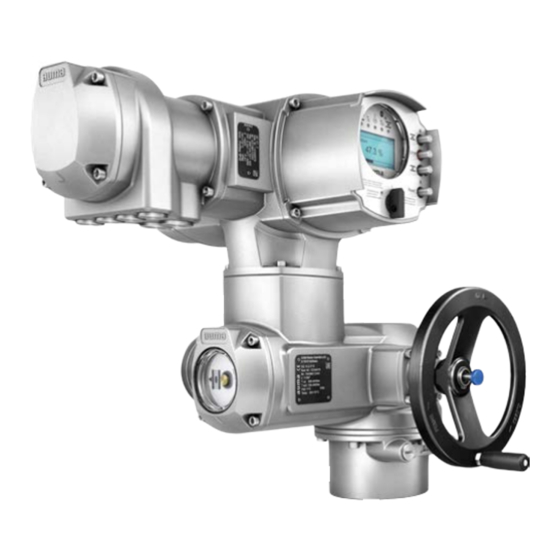
AUMA SQ 05.2 Operation Instructions Manual (96 pages)
Part-turn actuators
Brand: AUMA
|
Category: Controller
|
Size: 2 MB
Table of Contents
Advertisement
AUMA SQ 05.2 Operation Instructions Manual (96 pages)
Part-turn actuators
Brand: AUMA
|
Category: Controller
|
Size: 2 MB
Table of Contents

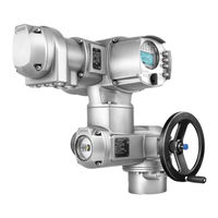
AUMA SQ 05.2 Operation Instructions Manual (92 pages)
Control unit - electromechanical with actuator controls
Brand: AUMA
|
Category: Control Unit
|
Size: 2 MB
Table of Contents
Advertisement


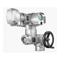
AUMA SQ 05.2 Operation Instructions Manual (72 pages)
Part-turn actuators with actuator controls
Brand: AUMA
|
Category: Controller
|
Size: 1 MB
Table of Contents

AUMA SQ 05.2 Manual (68 pages)
Part-turn actuators
Brand: AUMA
|
Category: Controller
|
Size: 1 MB
Table of Contents

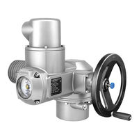
AUMA SQ 05.2 Operation Instructions Manual (56 pages)
Part-turn, NORM without controls
Brand: AUMA
|
Category: Controller
|
Size: 2 MB
Table of Contents

AUMA SQ 05.2 Manual (56 pages)
Part-turn actuators
Brand: AUMA
|
Category: Controller
|
Size: 1 MB
Table of Contents

AUMA SQ 05.2 Operating Instructions Manual (52 pages)
Part-turn actuators AUMA NORM actuator (without controls)
Brand: AUMA
|
Category: Controller
|
Size: 3 MB
Table of Contents
Advertisement