Sign In
Upload
Manuals
Brands
Agilent Technologies Manuals
Laboratory Equipment
G2260A
Agilent Technologies G2260A Manuals
Manuals and User Guides for Agilent Technologies G2260A. We have
3
Agilent Technologies G2260A manuals available for free PDF download: Reference Manual, User Manual
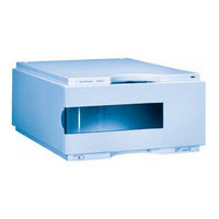
Agilent Technologies G2260A Reference Manual (278 pages)
Standard and Preparative Autosamplers
Brand:
Agilent Technologies
| Category:
Laboratory Equipment
| Size: 5.56 MB
Table of Contents
Table of Contents
5
1 Installing the Autosampler
13
Site Requirements
14
Power Consideration
14
Power Cords
15
Bench Space
15
Environment
16
Unpacking the Autosampler
17
Optimizing the Stack Configuration
21
Installing the Autosampler
26
Installing the Thermostatted Autosampler
29
Flow Connections
33
Sample Trays
35
Choice of Vials and Caps
38
Transporting the Autosampler
41
2 Optimizing Performance
43
Optimization for Lowest Carry-Over
44
Using the Automated Needle Wash
45
Using an Injector Program
46
General Recommendation to Lowest Carry-Over
47
Fast Injection Cycle and Low Delay Volume
48
Overlapped Injection Mode
48
General Recommendations for Fast Injection Cycle Times
49
Precise Injection Volume
50
Draw and Eject Speed
50
Choice of Rotor Seal
52
3 Troubleshooting and Test Functions
53
Overview of the Sampler's Indicators and Test Functions
54
Status Indicators
55
Power Supply Indicator
55
Instrument Status Indicator
56
Error Messages
57
Timeout
58
Shutdown
59
Remote Timeout
60
Synchronization Lost
61
Leak
62
Leak Sensor Open
63
Leak Sensor Short
64
Compensation Sensor Open
65
Compensation Sensor Short
66
Fan Failed
67
Open Cover
68
Restart Without Cover
69
Arm Movement Failed
70
Valve to Bypass Failed
71
Valve to Mainpass Failed
72
Needle up Failed
73
Needle down Failed
74
Missing Vial
75
Initialization Failed
76
Metering Home Failed
77
Motor Temperature
78
Initialization with Vial
79
Safety Flap Missing
80
Vial in Gripper
81
Missing Wash Vial
82
Invalid Vial Position
83
Maintenance Functions
84
User Interface
85
Change Needle
86
Change Piston
88
Park Arm (Park Gripper)
89
Change Gripper (Change Arm)
90
Tray Alignment
91
Step Commands
93
Troubleshooting
95
Troubleshooting Guide for the Sample Transport Assembly
97
Intermittent Lock-Ups with or Without Vial in the Gripper Fingers
98
Jittery (Shaky) Movement in X and or Theta Axes And/Or When the Needle Goes through the Gripper Arm into the Via
100
Poor Alignment, Seen During Vial Pickup and Vial Replacement And/Or When the Needle Hits the Gripper Arm
102
4 Repairing the Autosampler
105
Introduction into Repairing the Autosampler
106
Using the ESD Strap
107
Overview of Main Repair Procedures
109
Simple Repairs
110
Needle Assembly
111
Needle-Seat Assembly
114
Stator Face
117
Rotor Seal
120
Metering Seal and Plunger
124
Gripper Arm
128
Interface Board
131
Exchanging Internal Parts
132
Assembling the Main Cover
133
Top Cover and Foam
134
Installing the Top Cover and Foam
136
Illumination Assembly
138
Transport Assembly
139
Installing the Transport Assembly
140
Sampling Unit
141
Installing the Sampling Unit
144
Injection-Valve Assembly
147
Metering-Drive Motor and Belt
150
Needle-Drive Motor and Belt
152
Fan
155
ASM Board
157
Changing the Product Number or Serial Number
160
Using the Agilent Chemstation
160
Using the Instant Pilot G4208A
161
Using the Control Module G1323B
162
SUD Board
167
Power Supply
169
Leak Sensor
172
5 Parts and Materials
175
Main Assemblies
176
Sampling Unit Assembly
178
Analytical-Head Assembly
181
Injection-Valve Assembly
184
Sheet Metal Kit
186
Cover Parts
187
Foam Parts
188
Power and Status Light Pipes
189
Leak System Parts
190
Vial Trays
191
Standard Autosampler Accessory Kit G1329-68725
192
Preparative Autosampler Accessory Kit G2260-68705
193
Maintenance Kit G1313-68709
194
Multi-Draw Kit G1313-68711
195
900 Μl Injection Upgrade Kit G1363A for G1329A
196
External Tray G1313-60004
197
6 Identifying Cables
199
Cable Overview
200
Analog Cables
202
Remote Cables
205
BCD Cables
210
Auxiliary Cable
212
CAN Cable
213
External Contact Cable
214
RS-232 Cable Kit
215
LAN Cables
216
7 Introduction to the Autosampler
217
Introduction to the Autosampler
218
Sampling Sequence
220
Injection Sequence
221
Sampling Unit
223
Needle-Drive
224
Analytical Head / Preparative Head
224
Injection-Valve
225
Transport Assembly
226
Early Maintenance Feedback (EMF)
228
EMF Counters
228
Using the EMF Counters
229
Electrical Connections
230
8 Theory of Operation
233
Autosampler Control and Electronics
234
Position and Movement Sensors
235
Autosampler Main Board (ASM)
236
Firmware Description
241
Firmware Updates
242
Optional Interface Boards
243
BCD Board
243
LAN Communication Interface Board
245
Interfaces
247
Analog Signal Output
248
GPIB Interface
248
CAN Interface
248
Remote Interface
248
Rs-232C
250
Setting the 8-Bit Configuration Switch
252
GPIB Default Addresses
253
Communication Settings for RS-232C Communication
254
Forced Cold Start Settings
255
Stay-Resident Settings
256
The Main Power Supply Assembly
257
9 Specifications
259
Performance Specifications
260
A Safety Information
263
General Safety Information
264
Lithium Batteries Information
267
Radio Interference
268
Sound Emission
269
Solvent Information
270
Agilent Technologies on Internet
272
Index
273
Advertisement
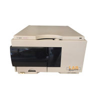
Agilent Technologies G2260A Reference Manual (292 pages)
1100 Series Standard, Micro and Preparative Autosamplers
Brand:
Agilent Technologies
| Category:
Laboratory Equipment
| Size: 5.44 MB
Table of Contents
Table of Contents
5
1 Installing the Autosampler
13
Site Requirements and Installation of the Autosampler and Thermostatted Autosampler
13
Site Requirements
14
Unpacking the Autosampler
17
Optimizing the Stack Configuration
22
Installing the Autosampler
26
Installing the Thermostatted Autosampler
28
Flow Connections
31
Sample Trays
32
Choice of Vials and Caps
35
Transporting the Autosampler
38
2 Optimizing Performance
39
How to Optimize the Autosamplers to Achieve Best Results
39
Optimization for Lowest Carry-Over
41
Fast Injection Cycle and Low Delay Volume
44
Precise Injection Volume
46
Choice of Rotor Seal
48
3 Troubleshooting and Test Functions
49
The Modules Built-In Troubleshooting and Test Functions
49
Status Indicators
51
Power Supply Indicator
52
Instrument Status Indicator
52
Error Messages
53
Timeout
54
Shutdown
55
Remote Timeout
56
Sychronization Lost
57
Leak
58
Leak Sensor Open
59
Leak Sensor Short
60
Compensation Sensor Open
61
Compensation Sensor Short
62
Fan Failed
63
Open Cover
64
Restart Without Cover
65
Arm Movement Failed
66
Valve to Bypass Failed
67
Valve to Mainpass Failed
68
Needle up Failed
69
Needle down Failed
70
Missing Vial
71
Initialization Failed
72
Metering Home Failed
73
Motor Temperature
74
Initialization with Vial
75
Safety Flap Missing
76
Vial in Gripper
77
Missing Wash Vial
78
Invalid Vial Position
79
Maintenance Functions
80
Change Needle
81
Change Piston
83
Park Arm (Park Gripper)
84
Change Gripper (Change Arm)
85
Tray Alignment
87
Step Commands
89
Troubleshooting Guide for the Sample Transport Assembly
94
Intermittent Lock-Ups with or Without Vial in the Gripper Fingers
95
Jittery (Shaky) Movement in X and or Theta Axes And/Or When the Needle Goes through the Gripper Arm into the Via
97
Poor Alignment, Seen During Vial Pickup and Vial Replacement And/Or When the Needle Hits the Gripper Arm
99
4 Repairing the Autosampler
101
Instructions on Simple, Routine Repair Procedures as Well as more Extensive Repairs Requiring Exchange of Internal Parts
101
Updating the Firmware
103
Cleaning the Autosampler
104
Using the ESD Strap
105
Overview of Main Repair Procedures
106
Simple Repairs
107
Needle Assembly
108
Needle-Seat Assembly
111
Stator Face
114
Rotor Seal
117
Metering Seal and Plunger
120
Gripper Arm
123
Interface Board
125
Exchanging Internal Parts
126
Assembling the Main Cover
127
Top Cover and Foam
128
Installing the Top Cover and Foam
130
Transport Assembly
132
Sampling Unit
134
Injection-Valve Assembly
140
Metering-Drive Motor and Belt
142
Needle-Drive Motor and Belt
144
Fan
146
ASM Board
148
SUD Board
152
Power Supply
154
Leak Sensor
157
5 Parts and Materials
159
Detailed Illustrations and Lists for Identification of Parts and Materials
159
Main Assemblies
160
Sampling Unit Assembly
162
Analytical-Head Assembly
165
Injection-Valve Assembly
168
Sheet Metal Kit
170
Cover Parts
171
Foam Parts
172
Power and Status Light Pipes
173
Leak System Parts
174
Vial Trays
175
Autosampler Accessory Kit G1313-68705
177
Thermostatted Autosampler Accessory Kit G1329-68705
178
Micro Thermostatted Autosampler Accessory Kit G1329-68715
179
Preparative als Accessory Kit G2260-68705
180
Maintenance Kit G1313-68709
181
Multi-Draw Kit G1313-68711
182
Μl Injection Upgrade Kit G1363A for G1313A / 29A
183
External Tray G1313-60004
184
Cable Overview
185
Analog Cables
187
Remote Cables
189
BCD Cables
195
Auxiliary Cable
197
CAN Cable
197
External Contact Cable
198
RS-232 Cable Kit
199
LAN Cables
200
Introduction to the Autosampler
201
An Introduction to the Standard, Micro and Preparative Autosamplers and Thermostatted Autosamplers
201
6 Introduction to the Autosampler Sampling Sequence
204
Sampling Sequence
204
Sampling Unit
207
Transport Assembly
210
Early Maintenance Feedback (EMF)
212
Electrical Connections
214
7 Theory of Operation
217
Theory of Operation of Mechanical Hardware, Electronics, and Instrument Interfaces
217
Autosampler Control and Electronics
218
Position and Movement Sensors
219
Autosampler Main Board (ASM)
220
Firmware Description
226
Optional Interface Boards
228
Interfaces
231
Setting the 8-Bit Configuration Switch
236
The Main Power Supply Assembly
241
8 Introduction to the Control Module
245
Introduction to the Screens Available for Operation of the Agilent 1100 Series Autosamplers with the Control Module
245
Screens Available from the Analysis Screen
247
Screens Available from the System Screen
258
Screens Available from the Records Screen
260
Diagnostics and Tests
264
9 Specifications
269
Performance Specifications of the Agilent 1100 Series Standard, Micro and Preparative Autosamplers
269
Performance Specifications
270
10 Legal, Safety and Warranty Information
275
Warranty Statement
276
Safety Information
279
Lithium Batteries Information
282
Radio Interference
283
Sound Emission
283
Solvent Information
284
Agilent Technologies on Internet
285
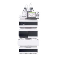
Agilent Technologies G2260A User Manual (150 pages)
1260 Infinity series. Preparative Autosampler
Brand:
Agilent Technologies
| Category:
Laboratory Equipment
| Size: 4.21 MB
Table of Contents
Table of Contents
3
Introduction to the Autosampler
7
Introduction to the Autosampler
8
Sampling Sequence
10
Injection Sequence
11
Sampling Unit
13
Needle-Drive
14
Analytical Head / Preparative Head
14
Injection-Valve
15
Transport Assembly
16
Early Maintenance Feedback (EMF)
18
Electrical Connections
19
Agilent 1200 Infinity Interfaces
21
2 Site Requirements and Specifications
23
Site Requirements
24
Power Consideration
24
Power Cords
25
Bench Space
26
Environment
26
Physical Specifications
27
Performance Specifications
28
3 Installing the Autosampler
33
Unpacking the Autosampler
34
Damaged Packaging
34
Delivery Checklist
34
Optimizing the Stack Configuration
37
Installing the Autosampler
41
Installing the Thermostatted Autosampler
44
Flow Connections
48
Installing the Sample Tray
50
Transporting the Autosampler
51
Using the Autosampler
53
Solvent Information
54
Sample Trays
56
Choice of Vials and Caps
58
5 Optimizing Performance
61
Optimization for Lowest Carry-Over
62
Using the Automated Needle Wash
63
Using an Injector Program
64
General Recommendation to Lowest Carry-Over
65
Fast Injection Cycle and Low Delay Volume
66
Overlapped Injection Mode
66
General Recommendations for Fast Injection Cycle Times
67
Precise Injection Volume
68
Draw and Eject Speed
68
Choice of Rotor Seal
70
Troubleshooting and Diagnostics
71
Agilent Lab Monitor & Diagnostic Software
72
Overview of the Sampler's Indicators and Test Functions
73
7 Maintenance
75
Introduction into Maintenance and Repair
76
Simple Repairs
76
Exchanging Internal Parts
76
Safety Flap, Flex Board
76
Transport Assembly Parts
76
Updating the Firmware
77
Warnings and Cautions
78
Using the ESD Strap
78
Cleaning the Module
79
Overview of Main Repair Procedures
80
Early Maintenance Feedback (EMF)
82
EMF Counters
82
Using the EMF Counters
83
Maintenance Functions
84
Simple Repairs
85
Needle Assembly
86
Needle-Seat Assembly
89
Stator Face
91
Rotor Seal
94
Metering Seal and Plunger
98
Gripper Arm
102
Interface Board
104
8 Parts and Materials for Maintenance
105
Main Assemblies
106
Analytical-Head Assembly
108
Vial Trays
111
Standard Autosampler Accessory Kit G1329-68725
112
Preparative Autosampler Accessory Kit G2260-68705
113
Maintenance Kit G1313-68730 for G1329A
114
Maintenance Kit G1313-68719 for G1329B
115
Multi-Draw Kit G1313-6871
116
900 Μl Injection Upgrade Kit G1363A for G1329A
117
External Tray G1313-60004
118
Identifying Cables
119
Cable Overview
120
Analog Cables
122
Remote Cables
125
BCD Cables
130
External Contact Cable
132
CAN/LAN Cables
133
Auxiliary Cable
134
Cables
135
Appendix
137
General Safety Information
138
Lithium Batteries Information
142
Radio Interference
143
Sound Emission
144
Agilent Technologies on Internet
145
Advertisement
Advertisement
Related Products
Agilent Technologies G2257A
Agilent Technologies Nano Indenter G200
Agilent Technologies G2545A
Agilent Technologies G2570A GC/MSD
Agilent Technologies G2747A
Agilent Technologies G2625B
Agilent Technologies G1883
Agilent Technologies G1377A
Agilent Technologies 1260 Infinity G1315D
Agilent Technologies G4240A
Agilent Technologies Categories
Measuring Instruments
Laboratory Equipment
Test Equipment
Water Pump
Power Supply
More Agilent Technologies Manuals
Login
Sign In
OR
Sign in with Facebook
Sign in with Google
Upload manual
Upload from disk
Upload from URL