
Related Manuals for Congatec conga-CEVAL


Summary of Contents for Congatec conga-CEVAL
- Page 1 COM Express™ conga-CEVAL Detailed description of the congatec COM Express™ Type 2 evaluation carrier board User’s Guide (Rev C.x) Revision 1.0...
-
Page 2: Revision History
Revision History Revision Date (yyyy.mm.dd) Author Changes 2013.09.17 • Initial release. Copyright © 2012 congatec AG CEVA_c_m10 2/47... - Page 3 In no event shall congatec AG be liable for any incidental, consequential, special, or exemplary damages, whether based on tort, contract or otherwise, arising out of or in connection with this user’s guide or any other information...
- Page 4 This link icon is located in the top left corner of each page. It provides a direct link to the conga‑CEVAL connector layout diagram. Copyright Notice Copyright © 2007, congatec AG. All rights reserved. All text, pictures and graphics are protected by copyrights. No copying is permitted without written permission from congatec AG.
- Page 5 (c) arising from course of performance, course of dealing, or usage of trade. congatec AG shall in no event be liable to the end user for collateral or consequential damages of any kind. congatec AG shall not otherwise be liable for loss, damage or expense directly or indirectly arising from the use of the product or from any other cause.
-
Page 6: Technical Support
AG technicians and engineers are committed to providing the best possible technical support for our customers so that our products can be easily used and implemented. We request that you first visit our website at www.congatec.com for the latest documentation, utilities and drivers, which have been made available to assist you. -
Page 7: Table Of Contents
4.1.9 LVDS Flat Panel Interface ............28 4.1.9.1 Flat Panel and Backlight Power Supply ........29 4.1.9.2 Flat Panel and Backlight Power Supply Connection ....30 4.1.10 PCI Express x1 Connectors ............. 31 Copyright © 2012 congatec AG CEVA_c_m10 7/47... -
Page 8: Com Express™ Specification Overview
CPUs, chipsets and multiprocessor systems. The placement of the shielded 220‑pin connectors and the mounting holes are identical between these form factors. Note The conga-CEVAL COM Express™ Type 2 evaluation carrier board can host either Compact or Basic form factor CPU modules. Copyright © 2012 congatec AG CEVA_c_m10... - Page 9 Compact, Basic and Extended Form Factor Copyright © 2012 congatec AG CEVA_c_m10 9/47...
-
Page 10: Module Types Overview
‑/1 1xDDI The conga-CEVAL evaluation board uses the Type 2 pin-out definition. This pinout offers the balance between older technology such as PCI and Parallel ATA while providing the latest technologies including PCI Express, Serial ATA and PCI Express graphics. - Page 11 • Dual 24‑bit LVDS channels ExpressCards • Analog VGA • TV Out • HDA/AC ‘97 digital audio interface • Gigabit Ethernet • LPC interface • 8 GPIO pins Copyright © 2012 congatec AG CEVA_c_m10 11/47...
-
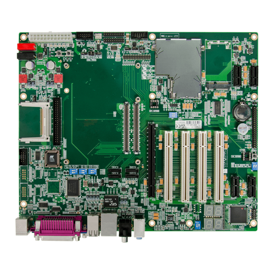
Page 12: Connector Layout
DEBUG DISPLAY For port selection USB 3 (up) LPT1 Line IN Mouse USB 2 Line Out (Up) USB 1 USB4 USB 0 COM1 (down) Keyboard (Down) ..USB5 ....Copyright © 2012 congatec AG CEVA_c_m10 12/47... -
Page 13: Specifications
X6: 2.54mm grid jumper. The conga‑CEVAL can also be used with 12V DC power supply (connector M2 and M7). Configuration Connector +12V Ground (M7) (M2) +12VDC (11,4 – 12,6V) Connector Type 4mm diameter plug Copyright © 2012 congatec AG CEVA_c_m10 13/47... - Page 14 5V_SB Standby Power Supply +5VDC Power Supply +5VDC +12V Power Supply +12DC Power Supply +5VDC +12V Power Supply +12DC Power Supply +5VDC +3.3V Power Supply +3.3VDC Power Ground Copyright © 2012 congatec AG CEVA_c_m10 14/47...
-
Page 15: Status Leds D1-D4
Add 3.3V Pullup with 10K to signal PWR_OK. PWRGOOD Config. 3 ‑ 4 Connect PWRGOOD of ATX power supply (default). (X11) 5 ‑ 6 Connect PWRGOOD of onboard DCDC regulator. Connector Type X11: 2.54 mm grid jumper. Copyright © 2012 congatec AG CEVA_c_m10 15/47... -
Page 16: Power-Up Control
If DC power input (M2, M7) is used, voltage regulators start after applying +12V. The native system power‑up support of congatec modules uses the ‘SUS_S3#’ signal to control the ‘PS_ON#’ signal, which switches the ATX power supply on or off. When using the SUS_S3#’ signal, the COM Express™ module is capable of supporting Suspend to RAM (S3). -
Page 17: Cmos Battery
12V indicates Pin‑out Rev.1.0 Note If an incompatible module pinout type is detected on the conga-CEVAL, an onboard logic will prevent the board from powering up the whole system by controlling the ‘PS_ON#’ signal of the ATX power supply. The ‘TYPE[0:2]0#’ signals are not present in Type 1 and Type 10 modules. -
Page 18: Connector Subsystems Rows A,B,C,D
LVDS_B_CK+ SATA2_RX‑ SATA3_RX‑ LVDS_A_CK+ BATLOW# LVDS_B_CK- LVDS_A_CK‑ LVDS_BKLT_CTRL (S)ATA_ACT# AC/HDA_SDIN2 LVDS_I2C_CK VCC_5V_SBY AC/HDA_SYNC AC/HDA_SDIN1 LVDS_I2C_DAT VCC_5V_SBY AC/HDA_RST# AC/HDA_SDIN0 GPI3 KBD_RST# VCC_5V_SBY GND (FIXED) GND (FIXED) AC/HDA_BITCLK KBD_A20GATE VCC_5V_SBY SPKR BIOS_DIS1# AC/HDA_SDOUT I2C_CK PCIE0_CK_REF+ Copyright © 2012 congatec AG CEVA_c_m10 18/47... -
Page 19: Sm Bus
SMB are normally powered by the 3.3V main power. To avoid current leakage between the main power of the carrier board and the standby power of the module, a bus switch separates the SMB on the conga-CEVAL carrier board from the SMB of the module. -
Page 20: I²C Bus
4.1.3 SPI Bus The SPI Bus is connected to the SPI BIOS flash that supports off-module BIOS flash boot. The conga-CEVAL revision C1 has onboard an SPI socket for 8‑lead Small Outline Integrated Circuit (200 mils). Copyright © 2012 congatec AG... -
Page 21: Hda Audio
The Realtek ALC888 HDA audio codec is mounted onboard the conga‑CEVAL. The stereo audio output interface of this codec is available on the X53 connector. The Windows driver for this audio codec can be found on the congatec website at www.congatec.com in the 'Products' section under 'Accessories'. -
Page 22: Hda/Ac97 Header X49
HDA/AC97 Header X49 The conga-CEVAL includes a HDA header (X49), which allows the connection of other AC'97/HDA solutions. By attaching a solution to this connector, the onboard codec switches off and the connected application is then operated. congatec developed a HDA evaluation sound board that features the VIA VT1708 HDA codec. -
Page 23: Lpc Super I/O Device
KBDAT DCD# DCD# MSDAT N.C. N.C. DTR# RTS# LPT1 KBCLK MSCLK CTS# N.C. N.C. RTS# DTR# COM1 CTS# (front view) ACK# +5V (750mA fuse) BUSY Mouse AUTOFD# Keyboard ERROR# INIT# SELIN# COM2 (X28) Copyright © 2012 congatec AG CEVA_c_m10 23/47... - Page 24 Mouse and Keyboard (X54): 6 pin MINI-DIN female COM1 (X55): 9 pin, D-SUB male. LPT1 (X55): 24 pin, D-SUB female. VGA: 15 pin, high density D-SUB female. COM2 (X28): 10 pin, 2 row 2.54mm grid header. Copyright © 2012 congatec AG CEVA_c_m10 24/47...
-
Page 25: Lpc Firmware Hubs
This can be very useful when a customized BIOS is evaluated. Onboard the conga-CEVAL is a 32-lead PLCC socket for LPC firmware hub (FWH in socket S1). With the DIP switch M46, you can configure which firmware hub the COM Express™ CPU module should boot from. When the yellow LED D28 is lit, this indicates the module boots with the BIOS located on the FWH in socket S1. -
Page 26: Lan 10/100/1000
SATA2 (X42) 7 6 5 4 3 2 1 7 6 5 4 3 2 1 The red LED D29 indicates activity on each SATA interface. Serial ATA Channel 3 Serial ATA Channel 2 Copyright © 2012 congatec AG CEVA_c_m10 26/47... -
Page 27: Vga
A CRT monitor can be connected using the X55 connector. Signal GREEN BLUE N.C. LPT1 DDC Power COM1 N.C. (front view) DDC DAT HSYNC VSYNC DDC CLK Connector Type VGA (X55): 15 pin, high density DSUB female Copyright © 2012 congatec AG CEVA_c_m10 27/47... -
Page 28: Lvds Flat Panel Interface
Backlight enable LOW active (inverted) 2 ‑ 3 Connector Type X69: 2.54mm grid jumper. Note See section 4.1.9.2 “Flat Panel and Backlight Power Supply Connection” for information about connection possibilities for the Backlight Polarity Config. jumper X69. Copyright © 2012 congatec AG CEVA_c_m10 28/47... -
Page 29: Flat Panel And Backlight Power Supply
2 ‑ 3 Connector Type X66 and X67: 2.54mm grid jumper Note See section 4.1.9.2 “Flat Panel and Backlight Power Supply Connection” for information about connection possibilities for the LCD Power X2 connector. Copyright © 2012 congatec AG CEVA_c_m10 29/47... -
Page 30: Flat Panel And Backlight Power Supply Connection
• Signals 1‑10 correspond to signals 1‑10 found on the X2 connector. • X66, X67 and X69 represent jumpers X66, X67 and X69 found on the conga-CEVAL. • The conga‑CEVAL carrier board is equipped with a Maxim MAX5362 device referred to in the diagram below as “DAC”. The DAC is a 6‑bit digital to analog converter.. -
Page 31: Pci Express X1 Connectors
Flat Panel Configuration Data The flat panel configuration data (EPI extended EDID™ 1.3 file) for most common displays is included in the congatec COM Express™ CPU module's system BIOS. The customer also has the possibility to store a customized EPI extended EDID™ 1.3 file in a serial EEPROM and then connect it on the conga‑CEVAL (DIL 8 socket S2). - Page 32 N.C. +3.3V N.C. N.C. +3.3V N.C. +3.3V +3.3V Standby +3.3V +3.3V Standby +3.3V WAKE0# PCIE_RST# WAKE0# PCIE_RST# N.C. N.C. PCIE_CLKS2+ PCIE_CLKS3+ PCIE_TX3+ PCIE_CLKS2‑ PCIE_TX4+ PCIE_CLKS3‑ PCIE_TX3‑ PCIE_TX4‑ PCIE_RX3+ PCIE_RX4+ PRSNT#2_S2 PCIE_RX3‑ PRSNT#2_S3 PCIE_RX4‑ Copyright © 2012 congatec AG CEVA_c_m10 32/47...
-
Page 33: Expresscard And Pci Express Mini Card
RSVD PCIE_CLKC0‑ RSVD PCIE_CLKC0+ SMB_CK SMB_DAT PCIE_RX2‑ +1.5V PCIE_RX2+ +1.5V WAKE0# PCIE_TX2‑ +3.3V Standby PCIE_TX2+ EXCD0_PERST# LED D24 is a red LED that indicates an 'Overcurrent Event' has occurred in the ExpressCard slot. Copyright © 2012 congatec AG CEVA_c_m10 33/47... -
Page 34: Pci Express Mini Card
PCIE_CLKC1‑ N.C. PCIE_CLKC1+ N.C. N.C. RSVD RSVD RSVD EXCD1_PERST# PCIE_RX5‑ +3.3V Standby PCIE_RX5+ +1.5V SMB_CK SMB_DAT PCIE_TX5‑ PCIE_TX5+ USB7- USB7+ RSVD RSVD RSVD LED_WWAN# RSVD LED_WLAN# RSVD LED_WPAN# RSVD +1.5V RSVD RSVD +3.3V Copyright © 2012 congatec AG CEVA_c_m10 34/47... - Page 35 ExpressCard slot uses PCI Express lane 2 and the PCI Express Mini Card socket uses PCI Express lane 5. In certain cases, it is necessary to use this DIP switch. For instance when dealing with some congatec COM Express™ modules that support onboard Gigabit Ethernet implemented with PCI Express lane 5.
-
Page 36: Tv-Out
S-VIDEO: 4 pin MINI-DIN female Note The conga-CEVAL rev C.1 does not support Composite Video Output by default because this pin is shared with SPI_CS# signal. To support this output on revision C.1, a simple hardware change is required. Copyright © 2012 congatec AG... -
Page 37: Connector Pinout Rows C And D
GND (FIXED) PEG_RX10‑ PEG_TX10‑ PCI_AD14 PCI_PAR PCI_C/BE1# PCI_SERR# PEG_RX11+ PEG_TX11+ PCI_PERR# PCI_STOP# PEG_RX11‑ PEG_TX11‑ PCI_LOCK# PCI_TRDY# GND (FIXED) GND (FIXED) PCI_DEVSEL# PCI_FRAME# PEG_RX12+ PEG_TX12+ PCI_IRDY# PCI_AD16 PEG_RX12‑ PEG_TX12‑ PCI_C/BE2# PCI_AD18 PCI_AD17 PCI_AD20 PEG_RX13+ PEG_TX13+ Copyright © 2012 congatec AG CEVA_c_m10 37/47... -
Page 38: Pci Express Graphics (Peg)
Express Graphics card. It supports a theoretical bandwidth of up to 4 GB/s. For information about the pinout of the PEG port connector refer to the 'PCI Express Card Electromechanical Specification, Rev. 1.1'. (X29) Copyright © 2012 congatec AG CEVA_c_m10 38/47... -
Page 39: Pata 100
CSEL IDE_D4 IDE_D11 IDE_ACK IDE_D3 IDE_D12 IDE_INTRQ N.C. CBLID_P# IDE_D2 IDE_D13 IDE_A1 IDE_D1 IDE_D14 IDE_A0 IDE_A2 IDE_D0 IDE_D15 IDE_CS1# IDE_CS3# N.C. ACTIVITY Connector Type X25: 40 pin, 2 row 2.54mm grid box header. Copyright © 2012 congatec AG CEVA_c_m10 39/47... -
Page 40: Compactflash Socket
CompactFlash Socket The conga-CEVAL has a CompactFlash socket (X26) that is connected to the PATA port. The CF card can be configured as either a Master or Slave device through the use of jumper X21. LED D25 indicates activity on the PATA port. -
Page 41: Pci Bus
'PCI Local Bus Specification Revision 2.3'. This interface is specified to be +5V tolerant with +3.3V signaling. All necessary PCI bus pull-up resistors are included on the COM Express™ module. A detailed pin description of the PCI connector can be found in the congatec COM Express™... -
Page 42: Additional Features
The DIP Switch M50 enables or disables the PC beeper as shown below: DIP Switch M50 Configuration SW1 On PC beeper enabled (default) SW1 Off PC beeper disabled SW2 On Carrier HDA codec disabled SW2 Off Carrier HDA codec enabled (default) Copyright © 2012 congatec AG CEVA_c_m10 42/47... -
Page 43: Debug Display
The conga-CEVAL decodes these ports and displays their contents on 4 seven-segment displays (D48 to D51). The dots in the first two displays show the state of the Reset and the PCI Frame signals. A list of the POST codes and associated POST test and initialization routines for the BIOS used on congatec COM Express™... -
Page 44: Fan Connector And Power Configuration
COM Express™ modules provide signals for fan control. This has been implemented through the use of some reserved pins. COM Express™ module pin C77 provides the FAN_TACHOIN signal that is attached to pin 3 of the fan connector X14 found on the conga-CEVAL. -
Page 45: Feature Connector
Power OK from main power supply. A high value (soft off), active on rising edge. indicates that the power is good. For additional information refer to PWRGOOD Config connector X11. Connector Type 40 pin, 2 row 2.54mm grid header. Copyright © 2012 congatec AG CEVA_c_m10 45/47... -
Page 46: Mechanical Drawing Conga-Ceval
Mechanical Drawing conga-CEVAL Copyright © 2012 congatec AG CEVA_c_m10 46/47... -
Page 47: Industry Specifications
IEEE standard 802.3ab 1000BASE T Ethernet http://www.ieee.org/portal/site Advanced Configuration and Power Interface Specification Rev. 3.0a http://www.acpi.info/ The following reference material from Mindshare Books is recommended by congatec AG. For more information and additional books visit www.mindshare.com. Title Author Ravi Budruk, Don Anderson, Tom Shanley...
Need help?
Do you have a question about the conga-CEVAL and is the answer not in the manual?
Questions and answers