Table of Contents
Advertisement
GB
Operating instructions
Machines for MIG/MAG, TIG and MMA welding
PHOENIX 301,351,421,521 EXPERT forceArc
PHOENIX 301,351,421,521 EXPERT PULS forceArc
PHOENIX 521 EXPERT HIGHSPEED
PHOENIX EXPERT DRIVE 4,4L,4HS
N. B. These operating instructions must be read before commissioning.
Failure to do so may be dangerous.
Machines may only be operated by personnel who are familiar with the appropriate safety
regulations.
The machines bear the conformity mark and thus comply with the
•
EC Low Voltage Directive (2006/95/ EG)
•
EC EMC Directive (2004/108/ EG)
In compliance with IEC 60974, EN 60974, VDE 0544 the machines can be used in environments
with an increased electrical hazard.
© 2007
Subject to alteration.
Dr. Günter - Henle - Straße 8 • D-56271 Mündersbach
Phone: +49 2680 181 0 • Fax: +49 2680 181 244
Item No.: 099-004833-EWM01
HIGHTEC WELDING GmbH
www.ewm.de
•
info@ewm.de
Revised: 03.12.2007
EWM
Advertisement
Table of Contents

Related Manuals for EWM PHOENIX 301 EXPERT forceArc


Summary of Contents for EWM PHOENIX 301 EXPERT forceArc
- Page 1 HIGHTEC WELDING GmbH Dr. Günter - Henle - Straße 8 • D-56271 Mündersbach Phone: +49 2680 181 0 • Fax: +49 2680 181 244 www.ewm.de • info@ewm.de Operating instructions Machines for MIG/MAG, TIG and MMA welding PHOENIX 301,351,421,521 EXPERT forceArc...
- Page 2 Congratulations! You have chosen a quality product from EWM HIGHTEC WELDING GmbH. EWM machines provide results of the highest perfection thanks to their PREMIUM quality. Therefore we are happy to provide you with a full 3-year warranty according to our operating instructions.
- Page 3 Machine and Company Data Please enter the EWM machine data and your company’s data in the appropriate fields. EWM HIGHTEC WELDING GMBH D-56271 MÜNDERSBACH TYP: SNR: ART: PROJ: GEPRÜFT/CONTROL: Name of Customer / company Name of Customer / company Adress...
-
Page 4: Table Of Contents
Contents For your safety Contents 1 Contents ..............................4 2 Safety instructions ..........................9 For your safety ..........................9 Transport and installation......................11 2.2.1 Ambient conditions .......................11 Safety rules while lifting........................12 Notes on the use of these operating instructions.................12 3 Technical data............................13 PHOENIX 301; 351 EXPERT forceArc ..................13 PHOENIX 421;... - Page 5 Contents For your safety 5.2.5.8 Latched mode with superpulse ..............48 5.2.5.9 Latched mode with alternating welding process ........... 49 5.2.5.10 Latched special ...................50 5.2.5.11 Latched special with welding process alternation........51 5.2.5.12 Special, latched with superpulse..............52 5.2.5.13 Latched special with alternating welding process........53 5.2.6 MIG/MAG automatic cut-out..................
- Page 6 Contents For your safety 5.5.2 RINT X11 robot interface ....................81 5.5.3 BUSINT X10 Industrial bus interface................81 5.5.4 DVINT X11 Wire feed interface ..................81 5.5.5 PC Interfaces ........................81 5.5.6 Setting options, internal ....................81 5.5.6.1 Switching between Push/Pull and intermediate drive ........81 Key switch ............................82 Operating time counter.........................82 Remote control..........................83...
- Page 7 10.2 Remote control / connection cable .................... 123 10.3 Options............................123 10.4 Computer communication......................123 11 Circuit diagrams..........................124 11.1 PHOENIX 301 EXPERT forceArc....................124 11.2 PHOENIX 351 EXPERT forceArc....................127 11.3 PHOENIX 421 EXPERT forceArc....................129 11.4 PHOENIX 521 EXPERT forceArc....................131 11.5 PHOENIX DRIVE 4; 4L; PHOENIX EXPERT DRIVE 4; 4L............133 11.6 PHOENIX EXPERT DRIVE 4HS ....................135...
- Page 8 Contents For your safety Item No.: 099-004833-EWM01...
-
Page 9: Safety Instructions
Safety instructions For your safety Safety instructions For your safety Observe accident prevention regulations! Ignoring the following safety procedures can be fatal! Proper usage This machine has been manufactured according to the latest developments in technology and current regulations and standards. It is to be operated only for the use for which it was designed (see chapter Commissioning/Area of application). - Page 10 Safety instructions For your safety Workpiece, flying sparks and droplets are hot! • Keep children and animals well away from the working area. Their behaviour is unpredictable. • Move containers with inflammable or explosive liquids away from the working area. There is a danger of fire and explosion.
-
Page 11: Transport And Installation
Safety instructions Transport and installation Transport and installation The machines may only be transported and operated in an upright position. Before carrying away or moving, pull out mains plug and place on the machine. When the power source is moved and positioned, it is only tilt resistant up to an angle of 10° (as specified in EN 60974-A2). -
Page 12: Safety Rules While Lifting
Safety instructions Safety rules while lifting Safety rules while lifting Carefully observe the accident prevention regulations VBG 9, VBG 9a and VGB 15. Machines must be connected on the lifting lugs when being lifted by crane (not on the transport bar)! •... -
Page 13: Technical Data
Technical data PHOENIX 301; 351 EXPERT forceArc Technical data PHOENIX 301; 351 EXPERT forceArc PHOENIX Adjusting range Welding current/voltage: 5A/10.2V - 300A/22.0V 5 A/10.2V - 350A/24.0V 5A/20.2V - 300A/32.0V 5 A/20.2V - 350A/34.0V 5A/14.3V - 300A/29.0V 5A/14.3V - 350A/31.5V MIG/MAG Duty cycle at 20C 80% DC 300A... -
Page 14: Phoenix 421; 521 Expert Forcearc
Technical data PHOENIX 421; 521 EXPERT forceArc PHOENIX 421; 521 EXPERT forceArc PHOENIX Adjusting range Welding current/voltage: 5A/10.2V - 420A/26.8V 5A/10.2V - 520A/40.8V 5A/20.2V - 420A/36.8V 5A/20.2V - 520A/40.8V 5A/14.3V - 420A/35.0V 5A/14.3V - 520A/40.0V MIG/MAG Duty cycle at 20C 420A 520A 80% DC... -
Page 15: Phoenix Drive 4; 4L; Phoenix Expert Drive 4; 4L
Technical data PHOENIX DRIVE 4; 4L; PHOENIX EXPERT DRIVE 4; 4L PHOENIX DRIVE 4; 4L; PHOENIX EXPERT DRIVE 4; 4L PHOENIX DRIVE 4 DRIVE 4L 42 VAC / 60 VDC Supply voltage 520 A Max. welding current at 60% DC 0.5 m/min to 24 m/min Wire feed speed 1.0 + 1.2 mm (for steel wire) -
Page 16: Machine Description
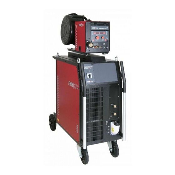
Machine description PHOENIX 301; 351; 421; 521 EXPERT forceArc Machine description PHOENIX 301; 351; 421; 521 EXPERT forceArc 4.1.1 Front view The maximum possible machine configuration is given in the text description. If necessary, the optional connection may need to be retrofitted (see "Accessories" chapter). Figure 4-1 Item No.: 099-004833-EWM01... -
Page 17: Machine Description
Machine description PHOENIX 301; 351; 421; 521 EXPERT forceArc Item Symbol Description Wire feed unit Lifting lug Carrying handle Main switch, machine on/off Cooling air inlet “Automatic cut-out of coolant pump” key button (press to reset a triggered fuse) Conveyor rolls, guide castors Coolant tank Coolant tank cap Connection socket, "-"... -
Page 18: Rear View
Machine description PHOENIX 301; 351; 421; 521 EXPERT forceArc 4.1.2 Rear view Figure 4-2 Item No.: 099-004833-EWM01... - Page 19 Machine description PHOENIX 301; 351; 421; 521 EXPERT forceArc Item Symbol Description Lifting lug "Automatic cutout" key button Wire feed motor supply voltage fuse (press to reset a triggered fuse) 42V/4A 7-pole connection socket (digital) Wire feed unit connection 7-pole connection socket (digital) For connecting digital accessory components (documentation interface, robot interface digital or remote control, etc.).
-
Page 20: Phoenix Drive 4L; Phoenix Expert Drive 4L
Machine description PHOENIX DRIVE 4L; PHOENIX EXPERT DRIVE 4L PHOENIX DRIVE 4L; PHOENIX EXPERT DRIVE 4L 4.2.1 Front view Figure 4-3 Item No.: 099-004833-EWM01... - Page 21 Machine description PHOENIX DRIVE 4L; PHOENIX EXPERT DRIVE 4L Item Symbol Description Slide latch, lock for the protective cap Cover for wire delivery unit and operating elements Carrying handle with integrated lifting lug Wire spool casing Operating elements (see chapter Function specification) Spool holder Wire delivery unit Euro-central connector (welding torch connection)
-
Page 22: Rear View
Machine description PHOENIX DRIVE 4L; PHOENIX EXPERT DRIVE 4L 4.2.2 Rear view Figure 4-4 Item Symbol Description Intermediate tube package strain relief 7-pole connection socket (digital) • Control lead for wire feed unit Connecting nipple G¼, shielding gas connection Rapid-action closure coupling, red (coolant return) Rapid-action closure coupling, blue (coolant supply) Connector plug, welding current "+"... -
Page 23: Phoenix Drive 4; Phoenix Expert Drive 4
Machine description PHOENIX DRIVE 4; PHOENIX EXPERT DRIVE 4 PHOENIX DRIVE 4; PHOENIX EXPERT DRIVE 4 4.3.1 Front view Figure 4-5 Item Symbol Description Cover for wire delivery unit and operating elements Transport bar Control / Operating elements (see chapter Function specification) Rubber feet Recessed grip (catch) for opening the cover Slide latch, lock for the protective cap... -
Page 24: Inside View
Machine description PHOENIX DRIVE 4; PHOENIX EXPERT DRIVE 4 4.3.2 Inside view Figure 4-6 Item No.: 099-004833-EWM01... - Page 25 Machine description PHOENIX DRIVE 4; PHOENIX EXPERT DRIVE 4 Item Symbol Description Operating elements (see chapter Function specification) Wire delivery unit 7-pole connection socket (digital) • Control lead for wire feed unit Connecting nipple G¼, shielding gas connection Spool holder Rapid-action closure coupling, blue (coolant supply) Connector plug, welding current "+"...
-
Page 26: Functional Characteristics
Functional characteristics Machine control – Operating elements Functional characteristics Machine control – Operating elements 5.1.1 Welding machine control Figure 5-1 Item Symbol Description "Up" and "Down" buttons, left Switching of the digital display between the following welding parameters: Welding current (nominal, actual and hold values) Material thickness (nominal value) Wire speed (nominal, actual and hold values) Operating hour counter... - Page 27 Functional characteristics Machine control – Operating elements Item Symbol Description SG2/3 "Select material type" key button G3/4 Si1 CrNi SG2/3 Steel CrNiMn G3/4 Si1 CuSi CuSi Chrome / nickel CrNi CuAl Chrome / nickel / manganese CrNiMn AlMg AlSi AlSi Copper / silicon CuSi Al99...
-
Page 28: M3.70 Wire Feed Unit Control
Functional characteristics Machine control – Operating elements 5.1.2 M3.70 wire feed unit control EXPERT M 3.70 Super- puls VOLT PROG HOLD m/min Figure 5-2 Item Symbol Description “Parameter selection ” (left) Welding current (nominal, actual and hold values) HOLD Material thickness (nominal value) Wire speed (actual, nominal and hold values) After each completed welding process, the last parameter values HOLD... - Page 29 Functional characteristics Machine control – Operating elements Item Symbol Description “Select welding parameters” button MIG/MAG standard welding MIG/MAG pulse arc welding (EXPERT PULS only) LCD display, 3-digit (right) Display of the parameters and values: Welding voltage, program number, coolant throughput, gas flow throughput VOLT “Parameter selection ”...
-
Page 30: Covered Operating Elements
Functional characteristics Machine control – Operating elements 5.1.2.1 Covered operating elements EXPERT M 3.70 Super- puls Figure 5-3 Item Symbol Description “Select welding parameters” button This button is used to select the welding parameters depending on the welding process and operating mode used. LED "Gas pre-flow time"... - Page 31 Functional characteristics Machine control – Operating elements Item Symbol Description LED "Gas post-flow time" Setting range 0.0 sec to 20.0 sec "Superpulse" LED Super- On when the function is activated puls "Special job" button Select the special jobs SP1 to SP3 (JOB 129 to 131) “Wire inching”...
-
Page 32: M3.00 Wire Feed Unit Control
Functional characteristics Machine control – Operating elements 5.1.3 M3.00 wire feed unit control M 3.00 8 9 10 m/min - V + Figure 5-4 Item Symbol Description 6 7 8 9 10 “Wire speed” rotary dial Infinitely adjustable setting of the wire speed from min. to max. (welding output, one-dial operation) m/min “WF-min. -
Page 33: Operating Elements In The Machine
Functional characteristics Machine control – Operating elements 5.1.4 Operating elements in the machine Programm Up / Down PHOENIX DRIVE 4 L PHOENIX DRIVE 4 Figure 5-5 Item Symbol Description "Program or up/down function" changeover switch This changeover switch only affects the Powercontrol program torch For changing over welding programs with the Powercontrol program Programm torch, see "MIG/MAG Powercontrol program torch"... -
Page 34: Mig/Mag Welding
Functional characteristics MIG/MAG welding MIG/MAG welding 5.2.1 Definition of MIG/MAG welding tasks The PHOENIX product range has been designed so that it is very easy and quick to operate, but still provides all the functions one could ever need. 128 JOBs (welding tasks) have been pre-programmed for the most common applications. The JOB is defined using the four basic welding parameters of welding process, material type, wire diameter and gas type. - Page 35 Functional characteristics MIG/MAG welding Item Description "Wire speed" rotary dial "Arc length correction" rotary dial "Select welding process" button "Select material type" key button "Select wire diameter / select special jobs" key button "Select gas type" button Item No.: 099-004833-EWM01...
-
Page 36: Selecting Mig/Mag Welding Tasks
Functional characteristics MIG/MAG welding 5.2.2 Selecting MIG/MAG welding tasks 5.2.2.1 Basic welding parameters The welding task is selected on the welding machine control. LEDs display the welding parameter selection. It is only possible to change the 4 basic welding parameters if: •... -
Page 37: Superpulses
Functional characteristics MIG/MAG welding PHOENIX DRIVE 4 M3.7x -40 to +40 Select Dynamics welding parameter Dynamic" comes on. -40 to +40 Dynamics setting Arc harder and narrower m/min Arc softer and wider 5.2.2.5 Superpulses PHOENIX DRIVE 4 with M3.00 control: •... -
Page 38: Mig/Mag Operating Point
Functional characteristics MIG/MAG welding 5.2.3 MIG/MAG operating point The operating point (welding output) is specified using the principle of MIG/MAG one-dial operation, i.e. the user need only specify the operating point by setting the required wire speed, for example, and the digital system will calculate the optimum values for welding current and voltage (operating point). -
Page 39: Choke Effect / Dynamics
Functional characteristics MIG/MAG welding 5.2.3.4 Choke effect / dynamics PHOENIX DRIVE 4 M3.00 Operating Action Result Display element No change "Dynamic correction/choke effect" rotary switch Dynamic correction or choke effect setting in 9 stages (hard, narrow to soft, wide arc) PHOENIX DRIVE 4 M3.7x -40 to +40 Select Dynamics welding parameter... -
Page 40: Accessory Components For Operating Point Setting
Functional characteristics MIG/MAG welding 5.2.3.6 Accessory components for operating point setting Accessory component Description PHOENIX R10 remote control See "Remote controls" chapter PHOENIX R20 remote control See "Remote controls" chapter PHOENIX R40 remote control See Phoenix R40 operating instructions MIG/MAG Powercontrol program torch See "MIG/MAG Powercontrol program torch"... -
Page 41: Mig/Mag Functional Sequences / Operating Modes
Functional characteristics MIG/MAG welding 5.2.5 MIG/MAG functional sequences / operating modes The following applies during the wire creep phase: If there is no welding current flowing after 5 seconds (factory setting), the ignition process is cancelled (ignition error). The following applies during the welding phase: If the arc is broken during the welding process and is not re-ignited within 5 seconds (factory setting), there is an automatic cut-out. -
Page 42: Non-Latched Mode
Functional characteristics MIG/MAG welding 5.2.5.2 Non-latched mode Figure 5-8 Step 1 • Press and hold torch trigger. • Shielding gas is expelled (gas pre-flows). • Wire feed motor runs at “creep speed”. • Arc ignites after the wire electrode makes contact with the workpiece; welding current flows. •... -
Page 43: Non-Latched Operation With Superpulse
Functional characteristics MIG/MAG welding 5.2.5.3 Non-latched operation with superpulse Figure 5-9 Step 1 • Press and hold torch trigger. • Shielding gas is expelled (gas pre-flows). • Wire feed motor runs at “creep speed”. • Arc ignites after the wire electrode makes contact with the workpiece; welding current flows. •... -
Page 44: Special, Non-Latched
Functional characteristics MIG/MAG welding 5.2.5.4 Special, non-latched START Figure 5-10 Step 1 • Press and hold torch trigger • Shielding gas is expelled (gas pre-flows) • Wire feed motor runs at “creep speed”. • Arc ignites after the wire electrode makes contact with the workpiece, welding current is flowing (start program P for the time t START... -
Page 45: Spots
Functional characteristics MIG/MAG welding 5.2.5.5 Spots START Figure 5-11 The start time t must also be calculated at spot time t . The start and spot times are set in start the "Program steps mode" menu. Step 1 • Press and hold torch trigger. •... -
Page 46: Special, Non-Latched With Superpulse
Functional characteristics MIG/MAG welding 5.2.5.6 Special, non-latched with superpulse START Figure 5-12 Step 1 • Press and hold torch trigger • Shielding gas is expelled (gas pre-flows) • Wire feed motor runs at “creep speed”. • Arc ignites after the wire electrode makes contact with the workpiece, welding current is flowing (start program P for the time t START... -
Page 47: Latched Mode
Functional characteristics MIG/MAG welding 5.2.5.7 Latched mode Figure 5-13 Step 1 • Press and hold torch trigger • Shielding gas is expelled (gas pre-flows) • Wire feed motor runs at “creep speed”. • Arc ignites after the wire electrode makes contact with the workpiece; welding current flows. •... -
Page 48: Latched Mode With Superpulse
Functional characteristics MIG/MAG welding 5.2.5.8 Latched mode with superpulse Figure 5-14 Step 1: • Press and hold torch trigger • Shielding gas is expelled (gas pre-flows) • Wire feed motor runs at “creep speed”. • Arc ignites after the wire electrode makes contact with the workpiece; welding current flows. •... -
Page 49: Latched Mode With Alternating Welding Process
Functional characteristics MIG/MAG welding 5.2.5.9 Latched mode with alternating welding process Pulse arc welding machines only. 1st cycle: • Press and hold torch trigger • Shielding gas is expelled (gas pre-flows) • Wire feed motor runs at "creep speed" • Arc ignites after the wire electrode makes contact with the workpiece;... -
Page 50: 5.2.5.10 Latched Special
Functional characteristics MIG/MAG welding 5.2.5.10 Latched special START Figure 5-15 Step 1 • Press and hold torch trigger • Shielding gas is expelled (gas pre-flows) • Wire feed motor runs at “creep speed”. • Arc ignites after the wire electrode makes contact with the workpiece, welding current is flowing (start program P START Step 2... -
Page 51: 5.2.5.11 Latched Special With Welding Process Alternation
Functional characteristics MIG/MAG welding 5.2.5.11 Latched special with welding process alternation Pulse arc welding machines only. START Figure 5-16 1st cycle • Press and hold torch trigger. • Shielding gas is expelled (gas pre-flows) • Wire feed motor runs at "creep speed" •... -
Page 52: 5.2.5.12 Special, Latched With Superpulse
Functional characteristics MIG/MAG welding 5.2.5.12 Special, latched with superpulse START Figure 5-17 Step 1 • Press and hold torch trigger • Shielding gas is expelled (gas pre-flows) • Wire feed motor runs at “creep speed”. • Arc ignites after the wire electrode makes contact with the workpiece, welding current is flowing (start program P for the time t START... -
Page 53: 5.2.5.13 Latched Special With Alternating Welding Process
Functional characteristics MIG/MAG welding 5.2.5.13 Latched special with alternating welding process Pulse arc welding machines only. START Figure 5-18 1st cycle • Press and hold torch trigger • Shielding gas is expelled (gas pre-flows) • Wire feed motor runs at "creep speed" •... -
Page 54: Mig/Mag Program Sequence ("Program Steps" Mode)
Functional characteristics MIG/MAG welding 5.2.7 MIG/MAG program sequence ("Program steps" mode) Certain materials, such as aluminium, require special functions in order to be able to weld them safely and at high quality. The latched special operating mode is used here with the following programs: •... -
Page 55: Mig/Mag Overview Of Parameters For M3.1X
Functional characteristics MIG/MAG welding 5.2.7.3 MIG/MAG overview of parameters for M3.1x START DVstart Ustart DVend Uend tstart tend Figure 5-20 Basic parameters Display Meaning/explanation Setting range GASstr Gas pre-flow time 0.0s to 20.0s "P " start program START DVstr (r) Wire-feed speed, relative 1% to 200% DVstr (a) -
Page 56: Mig/Mag Overview Of Parameters, M3.70
Functional characteristics MIG/MAG welding 5.2.7.4 MIG/MAG overview of parameters, M3.70 EXPERT M 3.70 Super- puls Figure 5-21 Basic Parameters Item Display Meaning / Explanation Setting Range left right Gas pre-flow time 0.0s to 20.0s DVstr (r) Wire speed, relative 1% to 200% DVstr (a) Wire speed, absolute 0.1 m/min to 40 m/min... -
Page 57: Example, Tack Welding (Non-Latched)
Functional characteristics MIG/MAG welding 5.2.7.5 Example, tack welding (non-latched) Figure 5-22 Basic parameters Display Meaning / explanation Setting range GASstr Gas pre-flow time 0.0s to 20.0s GASend: Gas post-flow time 0.0s to 20s RUECK Wire burn-back length 2 to 500 "P "... -
Page 58: Example, Aluminium Welding (Latched Special)
Functional characteristics MIG/MAG welding 5.2.7.7 Example, aluminium welding (latched special) START Figure 5-24 Basic parameters Display Meaning / explanation Setting range GASstr Gas pre-flow time 0.0s to 20.0s GASend: Gas post-flow time 0.0s to 20s RUECK Wire burn-back length 2 to 500 "P "... -
Page 59: Example, Visible Seams (Latched Super Pulse)
Functional characteristics MIG/MAG welding 5.2.7.8 Example, visible seams (latched super pulse) START Basic parameters Display Meaning / explanation Setting range GASstr Gas pre-flow time 0.0s to 20.0s GASend: Gas post-flow time 0.0s to 20s RUECK Wire burn-back length 2 to 500 PROC.SP. -
Page 60: Welding Process Changeover
Functional characteristics MIG/MAG welding 5.2.7.9 Welding process changeover Pulse arc welding machines only. START Figure 5-25 Program Setting option Relates to Setting All special, non-latched 1 (= on) Pulse arc welding process on/off START Changes using PC300.Net software All special, latched 0 (= off) Non-latched/latched mode 1 (= active) -
Page 61: Main Program A Mode
Functional characteristics MIG/MAG welding 5.2.8 Main program A mode Different welding tasks or positions on a workpiece demand various welding performances (operating points) or welding programs. The following parameters are stored in each of the up to 16 programs: • Operating mode •... - Page 62 Functional characteristics MIG/MAG welding Example 1: Welding workpieces with different sheet metal thicknesses (non-latched) Figure 5-26 Example 2: Welding different positions on a workpiece (latched) Figure 5-27 Example 3: Aluminium welding of different sheet metal thicknesses (non-latched or latched special) Figure 5-28 This mode can be used to define 16 different programs (P to P...
-
Page 63: Selecting Parameters (Program A) Using Wire Feed Unit Control M3.1X
Functional characteristics MIG/MAG welding 5.2.8.1 Selecting parameters (program A) using wire feed unit control M3.1x Operating Action Result Display element Select main program A mode Program A Select the welding parameters using the buttons "Up" and "Down" (left) Change values for the selected welding parameter using the buttons "Up"... -
Page 64: Mig/Mag Overview Of Parameters For M3.1X
Functional characteristics MIG/MAG welding 5.2.8.3 MIG/MAG overview of parameters for M3.1x Different welding tasks or positions on a workpiece demand various welding outputs (operating points) or welding programs. For each program, the • Wire speed • Correction of the arc length and the •... -
Page 65: 5.2.10 Mig/Mag Powercontrol Program Torch
Functional characteristics MIG/MAG welding 5.2.10 MIG/MAG Powercontrol program torch The control leads for the torches described in this chapter are fitted with a 19-pole connection socket. 5.2.10.1 Powercontrol program torch with one rocker (standard function, factory setting) Retrieving welding programs and program sequences (program function) Changeover switch in WF unit to "Program"... -
Page 66: Powercontrol Program Torch With One Rocker (Special Function)
Functional characteristics MIG/MAG welding 5.2.10.3 Powercontrol program torch with one rocker (special function) Calling up welding JOBs (block JOB mode) In this operating mode, a total of 27 JOBs (welding tasks) divided into three blocks can be called up using the torch. Only program 1 can be used in these JOBs. -
Page 67: 5.2.11 Mig/Mag Push/Pull Welding Torch
Functional characteristics MIG/MAG welding 5.2.11 MIG/MAG Push/Pull welding torch The most important requirement for the greatest degree of efficiency and weld seam quality is the smooth conveyance of the wire electrode. This is particularly problematic when: • Longer tube packages are used, •... -
Page 68: 5.2.12 High-Speed Welding
Functional characteristics MIG/MAG welding 5.2.12 High-speed welding This chapter provides setting information and guideline values for high-speed welding and relates to the PHOENIX 521 Highspeed machine series only The following examples apply to mechanical welding. In manual welding, 1mm wire can also be used. In addition, 92%Ar / 8%CO , 82%Ar / 18%CO or 90%Ar / 5%CO... - Page 69 Functional characteristics MIG/MAG welding Panel thickness 20mm, parent metal ST.37-2, filler material SG 2 1.2mm Seam Gas/quantity Voltage / Curre Welding speed Stickout m/min correction nt (A) (cm/min) (mm) (free wire electrode end) Fillet weld 65%Ar, 8%CO , 0.5%O , 26.5He, 27.8 47.4 trough...
-
Page 70: Tig Welding
Functional characteristics TIG welding TIG welding 5.3.1 TIG welding task selection Control element Action Result Display The various welding processes are run through The nominal values until the signal light for the required welding for the welding process comes on. current and welding voltage are displayed. -
Page 71: Tig Arc Ignition
Functional characteristics TIG welding 5.3.4 TIG arc ignition 5.3.4.1 Liftarc Figure 5-31 The arc is ignited on contact with the workpiece: a) Carefully place the torch gas nozzle and tungsten electrode tip onto the workpiece and press the torch trigger (liftarc current flowing, regardless of the main current set). b) Incline the torch over the torch gas nozzle to produce a gap of approx. -
Page 72: Tig Function Sequences / Operating Modes
Functional characteristics TIG welding 5.3.5 TIG function sequences / operating modes The arc ignition takes place with Liftarc (see chapter "TIG Arc ignition"). After unsuccessful ignition or interruption of the welding procedure, the automatic cut-out takes place (see chapter "TIG Automatic cut-out"). The welding parameters are optimally preset for a multiplicity of applications (can be adapted if required (see chapter TIG Program sequence "Program-Steps mode"). -
Page 73: Non-Latched Mode
Functional characteristics TIG welding 5.3.5.2 Non-latched mode Figure 5-32 Selection • Select non-latched operating mode Step 1 • Press and hold torch trigger. • Shielding gas is expelled (gas pre-flows). The arc is ignited using liftarc. • Welding current flows with pre-selected setting. Step 2 •... -
Page 74: Latched Mode
Functional characteristics TIG welding 5.3.5.4 Latched mode Figure 5-34 Selection • Select latched operating mode Step 1 • Press and hold torch trigger • Shielding gas is expelled (gas pre-flows) The arc is ignited using liftarc. • Welding current flows with pre-selected setting. Step 2 •... -
Page 75: Latched Special
Functional characteristics TIG welding 5.3.5.5 Latched special START Figure 5-35 Selection • Select latched special mode Step 1 • Press and hold torch trigger. • Shielding gas is expelled (gas pre-flows). The arc is ignited using liftarc. • Welding gas flows at pre-selected setting in start program "P ". -
Page 76: Tig Program Sequence ("Program Steps" Mode)
Functional characteristics TIG welding 5.3.7 TIG program sequence ("Program steps" mode) 5.3.7.1 TIG parameter overview The parameter settings are made on welding machine control M3.10 or M3.11 START Istart Iend tstart tend Figure 5-36 Basic parameters Display Meaning / explanation Setting range GASstr Gas pre-flow time... -
Page 77: Mma Welding
Functional characteristics MMA welding MMA welding 5.4.1 MMA welding task selection Control element Action Result Display The various welding processes are run through The nominal values until the signal light for the required welding for the welding process comes on. current and welding voltage are displayed. -
Page 78: Arcforcing
Functional characteristics MMA welding 5.4.4 Arcforcing Operating Action Result Display element -40 to +40 Select arcforcing welding parameter Press until “Dynamic” LED comes on. -40 to +40 Arcforcing setting on the "Wire speed/welding parameters" rotary dial m/min 5.4.5 Hotstart The hotstart device improves the ignition of the stick electrodes using an increased ignition current. a) = Hotstart time b) = Hotstart current Welding current... -
Page 79: Antistick
Functional characteristics MMA welding 5.4.6 Antistick Anti-stick prevents the electrode from annealing. If the electrode sticks in spite of the Arcforce device, the machine automatically switches over to the minimum current within about 1 second to prevent the electrode from overheating. Check the welding current setting and correct according to the welding task! Control element Action Result... -
Page 80: Interfaces
Functional characteristics Interfaces Interfaces Only the accessory components described in these operating instructions may be connected. Only plug accessory components into the relevant connection socket on the welding machine and lock it when the machine is switched off. The component is detected automatically when the welding machine is switched on. -
Page 81: Rint X11 Robot Interface
Functional characteristics Interfaces 5.5.2 RINT X11 robot interface The standard digital interface for automated applications (optional, retrofitting on the machine or external fitting by the customer) Functions and signals: • Digital inputs: Start/stop, operating mode, job and program selection, inching, gas test •... -
Page 82: Key Switch
Functional characteristics Key switch Key switch To protect against unauthorised or unintentional adjustment of the welding parameters on the machine, the control input can be locked with the aid of a key switch. In key switch position 1 all functions and parameters can be set without restriction. In key switch position 0 the following functions and parameters cannot be changed: •... -
Page 83: Remote Control
Functional characteristics Remote control Remote control Only the remote controls described in these operating instructions may be connected. Plug the remote control unit into the remote control connection socket on the welding machine or wire feed unit and lock it only when the machine is switched off. The remote control is detected automatically when the welding machine is switched on. -
Page 84: Manual Remote Control R20
Functional characteristics Remote control 5.8.2 Manual remote control R20 Manual remote controls R20 can only be used together with controls M3.70 or M3.71! Figure 5-39 Item Symbol Description 6 7 8 9 10 "Wire speed" rotary dial • Infinitely adjustable setting of the wire speed from min. to max. (welding output, one-dial operation). -
Page 85: Advanced Functions On The Welding Machine Control
Functional characteristics Advanced functions on the welding machine control Advanced functions on the welding machine control 5.9.1 Displaying JOB information Information on the current JOB is displayed in this mode. In JOBs 127 and 128 (TIG & MMA), it is not possible to select the mode as it would not be relevant. Selection: Operating Action... -
Page 86: Creating A New Job In The Memory Or Copying A Job
Functional characteristics Advanced functions on the welding machine control 5.9.2.1 Creating a new JOB in the memory or copying a JOB It is normally possible to adjust all 256 JOBs individually. However, it is useful to issue a separate job number to special welding tasks. Define welding task which most closely matches the required application. -
Page 87: Using Block Mode (Block Job)
Functional characteristics Advanced functions on the welding machine control 5.9.2.4 Using Block mode (Block JOB) This function is only appropriate for use in combination with the M3.70 wire feed unit control and a Powercontrol program torch. See also the "Powercontrol program torch with one rocker (special function)" chapter Operating Action Result... -
Page 88: Switching The Hold Function On And Off
Functional characteristics Advanced functions on the welding machine control 5.9.3 Switching the Hold function on and off Operating Action Result Display element Select “Special Mode” Program steps Special Mode Hold-Fct Select the Hold function using the buttons “Up” and “Down” (left) Hold-Fct Use the buttons “Up”... -
Page 89: Resetting Jobs To Status On Delivery (Reset All)
Functional characteristics Advanced functions on the welding machine control 5.9.5 Resetting JOBs to status on delivery (Reset ALL) This function is used to reset JOBs 1-128 to the original status on delivery. JOBs 129-256 remain unchanged. Operating Action Result Display element Select “Special Mode”... -
Page 90: Advanced Functions On The Wire Feed Unit Control
Functional characteristics Advanced functions on the wire feed unit control 5.10 Advanced functions on the wire feed unit control 5.10.1 Special parameter, “M3.70/M3.71” The special parameters cannot be viewed directly since they are normally only set and stored once. The machine control offers the following special functions: 5.10.1.1 Special parameters list Function... -
Page 91: 5.10.1.2 Selecting, Changing And Saving Parameters
Functional characteristics Advanced functions on the wire feed unit control 5.10.1.2 Selecting, changing and saving parameters Operating Action Result Display element Left Right Switch off the welding machine Keep the key button pressed HOLD Switch on welding machine Release the key button Value HOLD Parameter selection... -
Page 92: Special Cycle In The Operating Modes Special Latched And Non-Latched (P5)
Functional characteristics Advanced functions on the wire feed unit control 5.10.1.8 Special cycle in the operating modes special latched and non-latched (P5) In the “normal” cycle of latched/non-latched the system starts with the start program Dvstart and subsequently enters into the main program DV2. In the “DV3 cycle”... -
Page 93: Program Changeover With Standard Torch (P8)
Functional characteristics Advanced functions on the wire feed unit control Operating Action Result Display (example) Element Left Right Press key button until only LED 7,5 (DV) 4 (prog.-no.) „PROG“ is shining Keep the key button pressed 0 (DVGrenz) 2.0 (UKorr) 4 sec. - Page 94 Functional characteristics Advanced functions on the wire feed unit control The number of programs (P ) corresponds to the cycle number specified under N cycle. 1st cycle • Press and hold torch trigger. • Shielding gas is expelled (gas pre-flows). •...
-
Page 95: 5.10.1.12 N Cycle Setting
Functional characteristics Advanced functions on the wire feed unit control 5.10.1.12 N cycle setting In general, "Program switching with standard torch" must be set to "2" (= special latched special) before setting the N cycle (see chapter Machine control M3.70/M3.71 – special parameters). Operating Action Result... -
Page 96: Commissioning
Commissioning General Commissioning General Warning – Risk from electrical current! Follow the safety instructions on the opening pages entitled “For your safety”. Connection and welding leads (e.g. electrode holder, welding torch, workpiece lead, interfaces) may only be connected when the machine is switched off. Area of application –... -
Page 97: Machine Cooling
Commissioning Machine cooling Machine cooling To obtain an optimal duty cycle from the power components, the following precautions should be observed: Ensure that the working area is adequately ventilated, • Do not obstruct the air inlets and outlets of the machine, •... -
Page 98: List Of Coolants
Commissioning Workpiece lead, general 6.6.1 List of coolants The following coolants may be used (for item nos., please see the Accessories chapter): Coolant Temperature range KF 23E (Standard) -10°C to +40°C KF 37E -20°C to +10°C DKF 23E (for plasma machines) 0°C to +40°C Observe the safety data sheets. -
Page 99: Mig/Mag Welding
Commissioning MIG/MAG welding MIG/MAG welding Warning – Risk from electrical current! If welding is carried out alternately using different methods and if a welding torch and an electrode holder remain connected to the machine, the open-circuit/welding voltage is applied simultaneously on all cables. The torch and the electrode holder should therefore always be placed on an insulated surface before starting work and during breaks. -
Page 100: Intermediate Tube Package Connection
Commissioning MIG/MAG welding 6.8.1 Intermediate tube package connection 6.8.1.1 Welding machine Figure 6-2 Item Symbol Description 7-pole connection socket (digital) Wire feed unit connection Connection socket, "+" welding current • MIG/MAG welding: Welding current to "WF" central connection/torch Connection socket, "-" welding current •... -
Page 101: Wire Feed Unit
Commissioning MIG/MAG welding 6.8.1.2 Wire feed unit The green/yellow earth cable must not be connected to the welding machine or wire feed unit (this is used for a different machine series)! Remove the earth cable or push it back into the tube package. Figure 6-3 Item Symbol Description... -
Page 102: Welding Torch Connection
Commissioning MIG/MAG welding 6.8.2 Welding torch connection We can only guarantee correct functioning of our machines when used with our range of welding torches. The correct spirals or cores must be used for the relevant wire diameter and wire type. Welding torch with insulatated liner: A capillary tube must be installed in the central connection. -
Page 103: Connection For Workpiece Lead
Commissioning MIG/MAG welding 6.8.3 Connection for workpiece lead Figure 6-5 Item Symbol Description Connection socket, "+" welding current • MIG/MAG cored wire welding: Workpiece connection • TIG welding: Workpiece connection • MMA welding: Workpiece or electrode holder connection Connection socket, "-" welding current •... -
Page 104: Fixing Of The Pin Reel (Adjustment Of The Pre-Tensioning)
Commissioning MIG/MAG welding 6.8.4 Fixing of the pin reel (adjustment of the pre-tensioning) As the spool brake at the same time also secures the wire spool retainer, the following working steps are to be carried out for every spool change and before every adjustment of the spool brake. -
Page 105: Inserting The Wire Spool
Commissioning MIG/MAG welding 6.8.5 Inserting the wire spool The pretensioning of the pin reel shall be checked before each wire spool replacement and before the adjustment of the spool brake, see chapter on fixing of the pin reel (adjustment of the pretensioning)! Standard D300 pin reels can be used. -
Page 106: Inching The Wire Electrode
Commissioning MIG/MAG welding 6.8.7 Inching the wire electrode To ensure optimum wire feeding, it is essential that the wire feed rollers match the applied wire electrode diameter and the type of material used (exchange if necessary). Slide new drive rollers into place so that the diameter of the wire electrode printed on the wire feed roller is visible. -
Page 107: Spool Brake Setting
Commissioning TIG welding 6.8.8 Spool brake setting The pretensioning of the pin reel shall be checked before each wire spool replacement and before the adjustment of the spool brake, see chapter on fixing of the pin reel (adjustment of the pretensioning)! Figure 6-10 Item... -
Page 108: Welding Torch Connection
Commissioning TIG welding 6.9.1 Welding torch connection Figure 6-11 Item Symbol Description Euro-central connector (welding torch connection) Welding current, shielding gas and torch trigger included Rapid-action closure coupling, blue (coolant supply) Rapid-action closure coupling, red (coolant return) Connection socket, "-" welding current •... -
Page 109: Connection For Workpiece Lead
Commissioning TIG welding 6.9.2 Connection for workpiece lead Figure 6-12 Item Symbol Description Connection socket, "+" welding current • MIG/MAG cored wire welding: Workpiece connection • TIG welding: Workpiece connection • MMA welding: Workpiece or electrode holder connection Connection socket, "-" welding current •... -
Page 110: Mma Welding
Commissioning MMA welding 6.10 MMA welding Caution: Risk of being crushed or burnt. When replacing spent or new stick electrodes • Switch off machine at the main switch • Wear appropriate safety gloves • Use insulated tongs to remove spent stick electrodes or to move welded workpieces and •... -
Page 111: 6.10.1 Connecting The Electrode Holder And Workpiece Lead
Commissioning MMA welding 6.10.1 Connecting the electrode holder and workpiece lead Figure 6-13 Item Symbol Description Connection socket, "+" welding current • MIG/MAG cored wire welding: Workpiece connection • TIG welding: Workpiece connection • MMA welding: Workpiece or electrode holder connection Connection socket, "-"... -
Page 112: Shielding Gas Supply
Commissioning Shielding gas supply 6.11 Shielding gas supply 6.11.1 Connecting the shielding gas supply Figure 6-14 Item Symbol Description Cylinder bracket Safety chain Pressure reducer Shielding gas cylinder Cylinder valve G ¼" crown nut Connecting nipple G¼, shielding gas connection No dirt must be allowed to enter the shielding gas supply as this would cause blockages. -
Page 113: 6.11.2 Gas Test
Commissioning Shielding gas supply 6.11.2 Gas test • Slowly open the gas cylinder valve. • Open the pressure reducer. • Switch on the power source at the main switch. • Press the gas test key button briefly. The shielding gas will then flow for approx. 25 sec. Pressing the key button again briefly will pause the test. -
Page 114: Maintenance And Testing
DIN EN 61010-1 Appendix A – Measuring Circuit A1. You as the user are tasked with ensuring that your EWM machines conform to the standard IEC/DIN EN 60974-4 and are tested with the relevant test equipment and measuring devices given above. -
Page 115: Scope Of The Test
Note: Even if the leakage current measurement according to the standard is only an alternative to the insulation resistance measurement, EWM recommends always performing both measurements, especially following repair work. The leakage current is based for the greater part on a physical effect other than the insulation resistance. -
Page 116: Measurement Of Protective Conductor Resistance
Maintenance and testing Test 7.3.7 Measurement of protective conductor resistance Measure between the plug earthed contact and accessible live parts, e.g. casing screws. During the measurement, the connection lead must be moved across the entire length, especially near the casing and plug inlet points. This should uncover any interruptions in the protective conductor. All conductive parts of the casing accessible from outside should also be tested to ensure a correct PE connection for safety class I. -
Page 117: Repair Work
Returns of defective equipment subject to warranty may only be made through your EWM sales partner. In the event of problems or queries, please contact the EWM Service Department directly (+49 (0) 2680 181 0). Use only genuine spare parts and replacement parts when replacing. When placing an order, please quote the type designation and item number, as well as the type, serial number and item number of the relevant equipment. -
Page 118: Disposing Of Equipment
Your administrative office will be pleased to inform you of the options. EWM participates in an approved waste disposal and recycling system and is registered in the Used Electrical Equipment Register (EAR) under number WEEE DE 57686922. -
Page 119: Warranty
• Wire feeds • Cooling units • Trolleys * If these are operated with genuine EWM accessories (such as intermediate tube package, remote control, remote control extension cable, coolant, etc.). 1-year warranty on: • Used EWM machines • Automation and mechanisation components •... -
Page 120: Warranty Declaration
This limitation does not apply to personal injuries or damage to property caused by negligent behaviour on the part of EWM. In no way will EWM be responsible for lost profits, indirect or subsequent damage. EWM is not liable for damages based on the claims of third parties. -
Page 121: Operating Problems, Causes And Remedies
Operating problems, causes and remedies Error messages (power source) Operating problems, causes and remedies Error messages (power source) All machines are subject to rigorous production and final checks. If, despite this, anything fails to work at any time, please check machine using the chart below. If none of the fault rectification procedures described leads to the correct functioning of the machine, please inform your authorised dealer. -
Page 122: Accessories, Options
Accessories, options General accessories Accessories, options 10.1 General accessories Type Designation Item no. KF 23E-10 Coolant (-10°C), 10 litres 094-000530-00000 KF 37E-10 Coolant (-20°C), 10 litres 094-006256-00000 AK300 Adapter for K300 basket coil 094-001803-00001 DM1 32L/MIN Manometer pressure reducer 094-000009-00000 G1 2M G1/4 R 2M Gas hose 094-000010-00001... -
Page 123: Remote Control / Connection Cable
Accessories, options Remote control / connection cable 10.2 Remote control / connection cable Type Designation Item no. PHOENIX R10 Remote control with WF speed correction 090-008087-00000 RA5 19POL 5M Remote control e.g. connection cable 092-001470-00005 RA10 19POL 10M Remote control e.g. connection cable 092-001470-00010 RA20 19POL 20M Remote control e.g. -
Page 124: Circuit Diagrams
Circuit diagrams PHOENIX 301 EXPERT forceArc Circuit diagrams Original format circuit diagrams are located inside the machine. 11.1 PHOENIX 301 EXPERT forceArc X7/1 X7/2 X7/3 X7/4 X7/5 X7/6 X7/7 X7/8 X7/9 X7/10 X7/11 X7/12 X7/13 X7/14 X7/15 X7/16 X7/17 X7/18 X13/1 Lüfter... - Page 125 Circuit diagrams PHOENIX 301 EXPERT forceArc Stecker X3 D-SUB 15polig X5/1 42VAC X5/2 0VAC X8/1 Fühlerspg. X8/2 Fühlerspg. D-Sub. D-Sub. D-Sub. D-Sub. 15polig 15polig 15polig 15polig Figure 11-2 Item No.: 099-004833-EWM01...
- Page 126 Circuit diagrams PHOENIX 301 EXPERT forceArc D-Sub. 9polig X19/1 X19/2 X1/1 X19/3 X1/2 X19/4 X1/3 X19/5 X3/12 X1/4 X19/6 X3/11 X1/5 X19/7 X3/10 X1/6 X19/8 X3/9 X1/7 Pumpe X19/9 X3/8 X1/8 X19/10 X3/7 X1/9 Lüfter X19/11 X3/6 X1/10 X19/12 X3/5...
-
Page 127: Phoenix 351 Expert Forcearc
Circuit diagrams PHOENIX 351 EXPERT forceArc 11.2 PHOENIX 351 EXPERT forceArc Stecker X3 D-SUB 15polig X5/1 42VAC X5/2 0VAC X8/1 Fühlerspg. X8/2 Fühlerspg. D-Sub. D-Sub. D-Sub. D-Sub. 15polig 15polig 15polig 15polig Figure 11-4 Item No.: 099-004833-EWM01... - Page 128 Circuit diagrams PHOENIX 351 EXPERT forceArc D-Sub. 9polig X19/1 X19/2 X1/1 X19/3 X1/2 X1/3 X19/4 X3/12 X1/4 X19/5 X3/11 X1/5 X19/6 X3/10 X1/6 X19/7 X3/9 X1/7 X19/8 Pumpe X3/8 X1/8 X19/9 X19/10 X3/7 X1/9 Lüfter X19/11 X3/6 X1/10 X19/12 X3/5 X1/11 X3/4 X1/12...
-
Page 129: Phoenix 421 Expert Forcearc
Circuit diagrams PHOENIX 421 EXPERT forceArc 11.3 PHOENIX 421 EXPERT forceArc Stecker X3 D-SUB 15polig X5/1 42VAC X5/2 0VAC X8/1 F hlerspg. X8/2 F hlerspg. D-Sub. D-Sub. D-Sub. D-Sub. 15polig 15polig 15polig 15polig Figure 11-6 Item No.: 099-004833-EWM01... - Page 130 Circuit diagrams PHOENIX 421 EXPERT forceArc D-Sub. 9polig X19/1 X19/2 X1/1 X19/3 X1/2 X19/4 X1/3 X3/12 X1/4 X19/5 X19/6 X3/11 X1/5 X3/10 X1/6 X19/7 X3/9 X1/7 X19/8 Pumpe X3/8 X1/8 X19/9 X3/7 X1/9 X19/10 L fter X19/11 X3/6 X1/10 X19/12 X3/5 X1/11 X3/4...
-
Page 131: Phoenix 521 Expert Forcearc
Circuit diagrams PHOENIX 521 EXPERT forceArc 11.4 PHOENIX 521 EXPERT forceArc Stecker X3 D-SUB 15polig X5/1 42VAC X5/2 0VAC X13/1 X13/2 X8/1 F hlerspg. X8/2 F hlerspg. D-Sub. D-Sub. D-Sub. D-Sub. 15polig 15polig 15polig 15polig Figure 11-8 Item No.: 099-004833-EWM01... - Page 132 Circuit diagrams PHOENIX 521 EXPERT forceArc D-Sub. 9polig X19/1 X1/1 X19/2 X1/2 X19/3 X1/3 X19/4 X3/12 X1/4 X19/5 X3/11 X1/5 X19/6 X3/10 X1/6 X19/7 X3/9 X1/7 X19/8 Pumpe X3/8 X1/8 X19/9 X19/10 X3/7 X1/9 L fter X3/6 X1/10 X19/11 X3/5 X1/11 X19/12 X3/4...
-
Page 133: Phoenix Drive 4; 4L; Phoenix Expert Drive 4; 4L
Circuit diagrams PHOENIX DRIVE 4; 4L; PHOENIX EXPERT DRIVE 4; 4L 11.5 PHOENIX DRIVE 4; 4L; PHOENIX EXPERT DRIVE 4; 4L Figure 11-10 Item No.: 099-004833-EWM01... - Page 134 Circuit diagrams PHOENIX DRIVE 4; 4L; PHOENIX EXPERT DRIVE 4; 4L Stecker X2 Stecker X2 D-SUB D-SUB 15polig 15polig X24/1 X24/1 Motor+ Motor+ X24/2 X24/2 X20/1 X20/1 Motor Motor Motor- Motor- X20/2 X20/2 X24/3 X24/3 Motor Motor X24/4 X24/4 X10/1 X10/1 Tacho Tacho...
-
Page 135: Phoenix Expert Drive 4Hs
Circuit diagrams PHOENIX EXPERT DRIVE 4HS 11.6 PHOENIX EXPERT DRIVE 4HS Stecker X2 D-SUB 15polig X24/1 Motor+ X20/1 X24/2 Motor Motor- X20/2 X24/3 Motor X24/4 X10/1 Tacho X23/1 X10/2 Tacho X23/2 X10/3 Tacho X23/3 X10/4 X23/4 X3/1 X3/2 X19/1 X2/1 +10V X19/2 X2/2... -
Page 136: Declaration Of Conformity
Umbauten, die nicht ausdrücklich von authorised by EWM. bées n’ayant pas été autorisés expressé- EWM autorisiert sind, verliert diese ment par EWM, cette déclaration devient Erklärung ihre Gültigkeit. caduque. Gerätebezeichnung: Description of the machine: Déscription de la machine: Gerätetyp:... -
Page 137: Job Mapping
Appendix B JOB Mapping Appendix B 13.1 JOB Mapping Item No.: 099-004833-EWM01... - Page 138 Appendix B JOB Mapping Item No.: 099-004833-EWM01...
- Page 139 Appendix B JOB Mapping Item No.: 099-004833-EWM01...
- Page 140 Appendix B JOB Mapping Item No.: 099-004833-EWM01...
- Page 141 Appendix B JOB Mapping Item No.: 099-004833-EWM01...
- Page 142 Appendix B JOB Mapping Item No.: 099-004833-EWM01...
- Page 143 Appendix B JOB Mapping Item No.: 099-004833-EWM01...
- Page 144 Appendix B JOB Mapping Item No.: 099-004833-EWM01...
- Page 145 Appendix B JOB Mapping Item No.: 099-004833-EWM01...
- Page 146 Appendix B JOB Mapping Item No.: 099-004833-EWM01...
Need help?
Do you have a question about the PHOENIX 301 EXPERT forceArc and is the answer not in the manual?
Questions and answers