Table of Contents
Advertisement
Quick Links
GB
Operating instructions
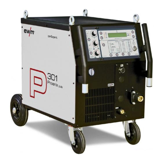
Compact welding machine for MIG brazing and
MIG/MAG welding
PHOENIX 301 CAR EXPERT PULS
N. B. These operating instructions must be read before commissioning.
Failure to do so may be dangerous.
Machines may only be operated by personnel who are familiar with the appropriate safety
regulations.
The machines bear the conformity mark and thus comply with the
•
EC Low Voltage Directive (73/23/EEC)
•
EC EMC Directive (89/336/EEC)
In compliance with IEC 60974, EN 60974, VDE 0544 the machines can be used in environments
with an increased electrical hazard.
© 2006
Subject to alteration.
Dr. Günter - Henle - Straße 8 • D-56271 Mündersbach
Phone: +49 2680 181 0 • Fax: +49 2680 181 244
Item No.: 099-004998-EWM01
HIGHTEC WELDING GmbH
www.ewm.de
•
info@ewm.de
Revised: 25.09.06
EWM
Advertisement
Table of Contents

Related Manuals for EWM PHOENIX 301 CAR EXPERT PULS


Summary of Contents for EWM PHOENIX 301 CAR EXPERT PULS
- Page 1 Operating instructions Compact welding machine for MIG brazing and MIG/MAG welding PHOENIX 301 CAR EXPERT PULS N. B. These operating instructions must be read before commissioning. Failure to do so may be dangerous. Machines may only be operated by personnel who are familiar with the appropriate safety regulations.
- Page 2 Umbauten, die nicht which have not been expressly allowed modifications prohibeés, qui n´ont pas été ausdrücklich von EWM autorisiert sind, by EWM, this declaration will lose its autorisés expressément par EWM, cette verliert diese Erklärung ihre Gültigkeit. validity. déclaration devient caduque.
- Page 3 Congratulations! You have chosen a quality product from EWM HIGHTEC WELDING GmbH. EWM machines provide results of the highest perfection thanks to their PREMIUM quality. Therefore we are happy to provide you with a full 3-year warranty according to our operating instructions.
- Page 4 Machine and Company Data Please enter the EWM machine data and your company’s data in the appropriate fields. EWM HIGHTEC WELDING GMBH D-56271 MÜNDERSBACH TYP: SNR: ART: PROJ: GEPRÜFT/CONTROL: Name of Customer / company Name of Customer / company Adress...
-
Page 5: Table Of Contents
Safety rules while lifting ....................... 10 Notes on the use of these operating instructions ................ 10 3 Technical data ............................11 4 Machine description ..........................12 PHOENIX 301 CAR EXPERT PULS ................... 12 4.1.1 Front view ........................12 4.1.2 Rear view........................13 5 Functional characteristics........................ - Page 6 Manufacturer's declaration to the end user ..............48 Meeting the requirements of RoHS....................48 8 3-Year Warranty ............................49 General Validity ..........................49 Warranty Declaration ........................50 9 Operating problems, causes and remedies..................51 Error messages (power source)....................51 10 Circuit diagrams ...........................52 10.1 PHOENIX 301 CAR EXPERT PULS ...................52 Item No.: 099-004998-EWM01...
-
Page 7: Safety Instructions
Safety instructions For your safety Safety instructions For your safety Observe accident prevention regulations! Ignoring the following safety procedures can be fatal! Proper usage This machine has been manufactured according to the latest developments in technology and current regulations and standards. It is to be operated only for the use for which it was designed (see chapter Commissioning/Area of application). - Page 8 Safety instructions For your safety Workpiece, flying sparks and droplets are hot! • Keep children and animals well away from the working area. Their behaviour is unpredictable. • Move containers with inflammable or explosive liquids away from the working area. There is a danger of fire and explosion.
-
Page 9: Transport And Installation
Safety instructions Transport and installation Transport and installation The machines may only be transported and operated in an upright position. Before carrying away or moving, pull out mains plug and place on the machine. When the power source is moved and positioned, it is only tilt resistant up to an angle of 10° (as specified in EN 60974-A2). -
Page 10: Safety Rules While Lifting
Safety instructions Safety rules while lifting Safety rules while lifting Carefully observe the accident prevention regulations VBG 9, VBG 9a and VGB 15. Machines must be connected on the lifting lugs when being lifted by crane (not on the transport bar)! •... -
Page 11: Technical Data
Technical data Notes on the use of these operating instructions Technical data 301 CAR EXPERT PULSE 5A/14.3V–300A/29.0V Welding current/voltage setting range: Duty cycle at 20°C 80% DC 300A 100% DC 270A Duty cycle at 40°C 300A 60% DC 100% DC 250A ∧... -
Page 12: Machine Description
Machine description PHOENIX 301 CAR EXPERT PULS Machine description PHOENIX 301 CAR EXPERT PULS 4.1.1 Front view Figure 4-1 Item Symbol Description Lifting lug Main switch, machine on/off Control / Operating elements (see chapter Function specification) Cooling air inlet 19-pole connection socket (analogue) -
Page 13: Rear View
Machine description PHOENIX 301 CAR EXPERT PULS 4.1.2 Rear view Figure 4-2 Item Symbol Description Shielding gas cylinder circlip Connecting nipple G¼, shielding gas connection "Automatic cutout" key button Wire feed motor supply voltage fuse (press to reset a triggered fuse) -
Page 14: Functional Characteristics
Functional characteristics Machine control – Operating elements Functional characteristics Machine control – Operating elements 5.1.1 Welding machine control Figure 5-1 Item Symbol Description “Up” and “Down” buttons, left Switching of the digital display between the following welding parameters: Welding current (nominal, actual and hold values) Panel thickness (nominal value) Wire speed Motor current... - Page 15 Functional characteristics Machine control – Operating elements Item Symbol Description 0,8 mm “Select wire diameter” key button 1,0 mm 0.8mm wire diameter 0,8 mm 1,2 mm 1.0mm wire diameter 1,0 mm 1.2mm wire diameter 1,2 mm 0,8 mm Panel thickness button 1,0 mm The signal light shows the selected panel thickness in mm.
-
Page 16: Wire Feed Machine Control
Functional characteristics Machine control – Operating elements 5.1.2 Wire feed machine control Figure 5-2 Item Symbol Description “Wire speed” rotary dial In conventional operation, infinite setting of the wire speed from 0.5 to 20m/min. (welding performance one-dial operation). No function in application-specific operation (factory setting) “Select operating mode”... -
Page 17: Internal Operating Elements
Functional characteristics Machine control – Operating elements 5.1.2.1 Internal operating elements Figure 5-3 Item Symbol Description “Program or up/down function” changeover switch This changeover switch only affects the CAR CONTROL program torch. Switch over the welding programs using the rocker on the CAR Programm CONTROL program torch. -
Page 18: Welding Torch Operating Elements
Functional characteristics Machine control – Operating elements 5.1.3 Welding torch operating elements Figure 5-4 Item Symbol Description “Seam type/program number” display Displays the selected seam type, or the selected welding program. Torch trigger – rocker Application-specific operation: Select seam types or welding programs Conventional operation: Control the WF speed in nine stages “Seam type”... -
Page 19: Application-Dependent Operation
Functional characteristics Application-dependent operation Application-dependent operation 5.2.1 Definition of MIG/MAG welding tasks This machine range has been designed to be very easy and quick to operate, whilst still providing all the functions one could ever need. The application-specific operation of this machine range combined with machine control M3.15 offers an intuitive operating interface covering typical welding tasks for every kind of bodywork repair. -
Page 20: Examples
Functional characteristics Application-dependent operation 5.2.3.2 Examples Figure 5-6 Pos. Seam shape Program Panel thicknesses Butt 0.8/0.8 1.2/1.2 Slot 1.2/1.2 Butt 0.8/0.8 For brazing work on a vehicle, there are optimised brazing programs specific to the manufacturer in JOB 4 (up to 8 possible). The relevant program number for each brazing position can be found in the welding instructions for the specific vehicle. -
Page 21: Conventional Operation
Functional characteristics Conventional operation Conventional operation 5.3.1 Definition of MIG/MAG welding tasks In addition to the application-specific operation of the CAR EXPERT range, it is possible to specify the operating point conventionally via one-dial operation. The welding task is selected via two basic welding parameters (material/gas type and wire electrode diameter). -
Page 22: Mig/Mag Operating Point
Functional characteristics Other parameters 5.3.3 MIG/MAG operating point The operating point (welding performance) is specified using the principle of MIG/MAG one-dial operation, i.e. the user need only specify the operating point by setting the required wire speed, for example, and the digital system will calculate the optimum values for welding current and voltage (operating point). -
Page 23: Mig/Mag Welding
Functional characteristics MIG/MAG welding MIG/MAG welding 5.5.1 MIG/MAG functional sequences / operating modes The following applies during the wire creep phase: If there is no welding current flowing after 5 seconds (factory setting), the ignition process is cancelled (ignition error). The following applies during the welding phase: If the arc is broken during the welding process and is not re-ignited within 5 seconds (factory setting), there is an automatic cut-out. -
Page 24: Non-Latched Mode
Functional characteristics MIG/MAG welding 5.5.1.2 Non-latched mode Figure 5-8 Step 1 • Press and hold torch trigger. • Shielding gas is expelled (gas pre-flows). • Wire feed motor runs at “creep speed”. • Arc ignites after the wire electrode makes contact with the workpiece; welding current flows. •... -
Page 25: Non-Latched Operation With Superpulse
Functional characteristics MIG/MAG welding 5.5.1.3 Non-latched operation with superpulse Figure 5-9 Step 1 • Press and hold torch trigger. • Shielding gas is expelled (gas pre-flows). • Wire feed motor runs at “creep speed”. • Arc ignites after the wire electrode makes contact with the workpiece; welding current flows. •... -
Page 26: Special, Non-Latched
Functional characteristics MIG/MAG welding 5.5.1.4 Special, non-latched START Figure 5-10 Step 1 • Press and hold torch trigger • Shielding gas is expelled (gas pre-flows) • Wire feed motor runs at “creep speed”. • Arc ignites after the wire electrode makes contact with the workpiece, welding current is flowing (start program P for the time t START... -
Page 27: Spots
Functional characteristics MIG/MAG welding 5.5.1.5 Spots Selecting Spot operating mode Operating Action Result Displays element No change Press until signal light comes on. • Press and hold for approx. 2 sec. until signal No change light flashes. The machine is switched over to Spot operating mode •... -
Page 28: Special, Non-Latched With Superpulse
Functional characteristics MIG/MAG welding 5.5.1.6 Special, non-latched with superpulse START Figure 5-12 Step 1 • Press and hold torch trigger • Shielding gas is expelled (gas pre-flows) • Wire feed motor runs at “creep speed”. • Arc ignites after the wire electrode makes contact with the workpiece, welding current is flowing (start program P for the time t START... -
Page 29: Latched Mode
Functional characteristics MIG/MAG welding 5.5.1.7 Latched mode Figure 5-13 Step 1 • Press and hold torch trigger • Shielding gas is expelled (gas pre-flows) • Wire feed motor runs at “creep speed”. • Arc ignites after the wire electrode makes contact with the workpiece; welding current flows. •... -
Page 30: Latched Mode With Superpulse
Functional characteristics MIG/MAG welding 5.5.1.8 Latched mode with superpulse Figure 5-14 Step 1: • Press and hold torch trigger • Shielding gas is expelled (gas pre-flows) • Wire feed motor runs at “creep speed”. • Arc ignites after the wire electrode makes contact with the workpiece; welding current flows. •... -
Page 31: Latched Special
Functional characteristics MIG/MAG welding 5.5.1.9 Latched special START Figure 5-15 Step 1 • Press and hold torch trigger • Shielding gas is expelled (gas pre-flows) • Wire feed motor runs at “creep speed”. • Arc ignites after the wire electrode makes contact with the workpiece, welding current is flowing (start program P START Step 2... -
Page 32: 5.5.1.10 Special, Latched With Superpulse
Functional characteristics MIG/MAG welding 5.5.1.10 Special, latched with superpulse START Figure 5-16 Step 1 • Press and hold torch trigger • Shielding gas is expelled (gas pre-flows) • Wire feed motor runs at “creep speed”. • Arc ignites after the wire electrode makes contact with the workpiece, welding current is flowing (start program P for the time t START... -
Page 33: Mig/Mag Automatic Cut-Out
Functional characteristics Key switch 5.5.2 MIG/MAG automatic cut-out If pressing the torch trigger does not ignite the arc or if the arc is interrupted by the torch being removed during the welding process, automatic cut-out occurs within 5 seconds. The welding machine ends the welding process immediately (open circuit voltage or welding current, wire feed and shielding gas are shut off). -
Page 34: Commissioning
Commissioning General Commissioning General Warning – Risk from electrical current! Follow the safety instructions on the opening pages entitled “For your safety”. Connection and welding leads (e.g. electrode holder, welding torch, workpiece lead, interfaces) may only be connected when the machine is switched off. Area of application –... -
Page 35: Mig/Mag Welding
Commissioning MIG/MAG welding MIG/MAG welding 6.7.1 Welding torch and workpiece line connection The welding torch must be set up with equipment appropriate to the welding task. The relevant measures to equip the torch for MIG brazing and MIG welding (CuSi & CuAl, or AlSi & AlMg) and for MAG welding (SG 2/3) are described below. - Page 36 Commissioning MIG/MAG welding The flow nozzle must match the application and for that reason may need to be changed. This depends on the welding wire and wire diameter being used. For example, aluminium and aluminium alloys with 0.8mm welding wire: Gas nozzle “0.8A” Remove the gas nozzle •...
-
Page 37: Preparing The Torch For Welding Steel
Commissioning MIG/MAG welding 6.7.1.2 Preparing the torch for welding steel Figure 6-2 Item Symbol Description Gas nozzle Flow contact nozzle Gas distributor Nozzle holder Nozzle holder mount Clamping nut Conically ground end of the guide spiral Guide spiral Holding nipple Remove the gas nozzle •... -
Page 38: Phoenix 301 Car Expert Puls
Commissioning MIG/MAG welding 6.7.1.3 PHOENIX 301 CAR EXPERT PULS We can only guarantee correct functioning of our machines when used with our range of welding torches. The correct spirals or cores must be used for the relevant wire diameter and wire type. -
Page 39: Removing The Wire Feed Unit Cover
Commissioning MIG/MAG welding 6.7.2 Removing the wire feed unit cover For the following processes the cover must be removed; to protect the machine it is essential that the cover is fitted back into position afterwards. • Unlock the right-hand cover on the machine. •... -
Page 40: Inserting The Wire Spool
Commissioning MIG/MAG welding 6.7.4 Inserting the wire spool The pretensioning of the pin reel shall be checked before each wire spool replacement and before the adjustment of the spool brake, see chapter on fixing of the pin reel (adjustment of the pretensioning)! Standard D300 pin reels can be used. -
Page 41: Inching The Wire Electrode
Commissioning MIG/MAG welding 6.7.6 Inching the wire electrode To ensure optimum wire feeding, it is essential that the wire feed rollers match the applied wire electrode diameter and the type of material used (exchange if necessary). Slide new drive rollers into place so that the diameter of the wire electrode printed on the wire feed roller is visible. -
Page 42: Spool Brake Setting
Commissioning MIG/MAG welding 6.7.7 Spool brake setting The pretensioning of the pin reel shall be checked before each wire spool replacement and before the adjustment of the spool brake, see chapter on fixing of the pin reel (adjustment of the pretensioning)! Figure 6-8 Item... -
Page 43: Shielding Gas Supply
Commissioning Shielding gas supply Shielding gas supply Figure 6-9 Item Symbol Description Cylinder bracket Shielding gas cylinder circlip Pressure reducer G ¼" crown nut Cylinder valve Shielding gas cylinder No dirt must be allowed to enter the shielding gas supply as this would cause blockages. All shielding gas connections must be gastight! •... -
Page 44: Maintenance And Care
DIN EN 61010-1 Appendix A – Measuring Circuit A1. You as the user are tasked with ensuring that your EWM machines conform to the standard E VDE 0544-207 and are tested with the relevant test equipment and measuring devices given above. -
Page 45: Test Intervals And Scope
Maintenance and care Repetition test 7.3.1 Test intervals and scope A quarterly partial test and an annual extensive test are to be carried out. The extensive test must also be carried out each time that repairs are made; in the case of heavy use, the period can be reduced (e.g. to 6 months when used at construction sites). -
Page 46: Measurement Of Insulation Resistance
Maintenance and care Repetition test 7.3.5 Measurement of insulation resistance The mains switch must be on before the insulation in the interior of the machine through to the transformer can be checked. If a mains contactor is fitted, this should be bridged or the measurement must be carried out on both sides. -
Page 47: Repair Work
Returns of defective equipment subject to warranty may only be made through your EWM sales partner. In the event of problems or queries, please contact the EWM Service Department directly (+49 (0) 2680 181 0). Use only original spare parts and replacement parts when servicing. When placing an order, please quote the type designation and item number, as well as the type, serial number and item number of the relevant equipment. -
Page 48: Disposing Of Equipment
Your administrative office will be pleased to inform you of the options. EWM participates in an approved waste disposal and recycling system and is registered in the Used Electrical Equipment Register (EAR) under number WEEE DE 57686922. -
Page 49: 3-Year Warranty
(such as circuit boards, ignition units) Manufacturer/supplier warranty on: • all additional parts used by EWM, but manufactured by other companies (e.g. motors, pumps, fans, torches, etc.) Non-reproducible software errors and parts subject to mechanical aging are excluded from the warranty (e.g. -
Page 50: Warranty Declaration
Furthermore, it is not valid in the case of unauthorised changes, repairs or modifications. In addition, a claim for warranty does not exist in the case of partially or completely dismantled products and interventions by persons who are not authorised by EWM, as well as in the case of normal wear. -
Page 51: Operating Problems, Causes And Remedies
Operating problems, causes and remedies Error messages (power source) Operating problems, causes and remedies Error messages (power source) All machines are subject to rigorous production and final checks. If, despite this, anything fails to work at any time, please check machine using the chart below. If none of the fault rectification procedures described leads to the correct functioning of the machine, please inform your authorised dealer. -
Page 52: Circuit Diagrams
Circuit diagrams PHOENIX 301 CAR EXPERT PULS Circuit diagrams Original format circuit diagrams are located inside the machine. 10.1 PHOENIX 301 CAR EXPERT PULS X7/1 X7/2 X7/3 400VAC X7/4 X7/5 X7/6 230VAC X7/7 X7/8 X7/9 0VAC X7/10 X7/11 X7/12 X7/13... - Page 53 Circuit diagrams PHOENIX 301 CAR EXPERT PULS X24/1 Motor+ X24/2 Motor- X24/3 X24/4 X17/1 X17/2 X17/3 X23/1 X17/4 X23/2 X17/5 X23/3 X17/6 X23/4 X20/1 X20/2 Tacho X10/1 X10/2 Tacho X10/3 Tacho X10/4 X2/1 +10V X2/2 LED-A X2/3 LED-B X2/4 LED-C...
Need help?
Do you have a question about the PHOENIX 301 CAR EXPERT PULS and is the answer not in the manual?
Questions and answers