Table of Contents
Advertisement
GB
Operating instructions
Welding machines for TIG and MMA welding
TETRIX 270, 300, 350, 500 AC/DC COMFORT activArc
N. B. These operating instructions must be read before commissioning.
Failure to do so may be dangerous.
Machines may only be operated by personnel who are familiar with the appropriate safety
regulations.
The machines bear the conformity mark and thus comply with the
•
EC Low Voltage Directive (2006/95/ EG)
•
EC EMC Directive (2004/108/ EG)
In compliance with IEC 60974, EN 60974, VDE 0544 the machines can be used in environments
with an increased electrical hazard.
© 2008
Subject to alteration.
Dr. Günter - Henle - Straße 8 • D-56271 Mündersbach
Phone: +49 2680 181 0 • Fax: +49 2680 181 244
Item No.: 099-004877-EWM01
HIGHTEC WELDING GmbH
www.ewm.de
•
info@ewm.de
Revised: 21.01.2008
EWM
Advertisement
Table of Contents

Related Manuals for EWM TETRIX 270 AC/DC COMFORT activArc


Summary of Contents for EWM TETRIX 270 AC/DC COMFORT activArc
- Page 1 HIGHTEC WELDING GmbH Dr. Günter - Henle - Straße 8 • D-56271 Mündersbach Phone: +49 2680 181 0 • Fax: +49 2680 181 244 www.ewm.de • info@ewm.de Operating instructions Welding machines for TIG and MMA welding TETRIX 270, 300, 350, 500 AC/DC COMFORT activArc N.
- Page 2 Congratulations! You have chosen a quality product from EWM HIGHTEC WELDING GmbH. EWM machines provide results of the highest perfection thanks to their PREMIUM quality. Therefore we are happy to provide you with a full 3-year warranty according to our operating instructions.
- Page 3 Machine and Company Data Please enter the EWM machine data and your company’s data in the appropriate fields. EWM HIGHTEC WELDING GMBH D-56271 MÜNDERSBACH TYP: SNR: ART: PROJ: GEPRÜFT/CONTROL: Name of Customer / company Name of Customer / company Adress...
-
Page 4: Table Of Contents
Contents For your safety Contents 1 Contents ..............................4 2 Safety instructions ..........................7 For your safety ..........................7 Transport and installation.......................9 2.2.1 Ambient conditions ......................9 Notes on the use of these operating instructions.................10 3 Technical data............................11 TETRIX 270; 300 AC/DC COMFORT activArc ................11 TETRIX 350 AC/DC COMFORT activArc ..................12 TETRIX 500 AC/DC COMFORT activArc ..................13 4 Machine description..........................14... - Page 5 Contents For your safety 5.3.9 TIG activArc welding..................... 47 5.3.10 TIG shielding gas setting....................48 5.3.10.1 Gas test....................... 48 5.3.11 TIG welding torch (operating variants) ................. 48 5.3.12 Torch mode and up/down speed setting ..............49 5.3.12.1 Standard TIG torch (5-pole) ................ 50 5.3.12.2 TIG up/down torch (8-pole) .................52 5.3.12.3...
- Page 6 10.5 Transport vehicle..........................83 10.6 Cooling units ..........................83 10.7 Synchronisation..........................83 11 Circuit diagrams ...........................84 11.1 TETRIX 270 AC/DC COMFORT activArc ..................84 11.2 TETRIX 300 AC/DC COMFORT activArc ..................86 11.3 TETRIX 350 AC/DC COMFORT activArc ..................88 11.4 TETRIX 500 AC/DC COMFORT activArc ..................90 12 Appendix A............................92...
-
Page 7: Safety Instructions
Safety instructions For your safety Safety instructions For your safety Observe accident prevention regulations! Ignoring the following safety procedures can be fatal! Proper usage This machine has been manufactured according to the latest developments in technology and current regulations and standards. It is to be operated only for the use for which it was designed (see chapter Commissioning/Area of application). - Page 8 Safety instructions For your safety Workpiece, flying sparks and droplets are hot! • Keep children and animals well away from the working area. Their behaviour is unpredictable. • Move containers with inflammable or explosive liquids away from the working area. There is a danger of fire and explosion.
-
Page 9: Transport And Installation
Safety instructions Transport and installation Transport and installation The machines may only be transported and operated in an upright position. Before carrying away or moving, pull out mains plug and place on the machine. When setting up the machine, resistance to tilting is only guaranteed up to an angle of 10° (as specified in EN 60974-1). -
Page 10: Notes On The Use Of These Operating Instructions
Safety instructions Notes on the use of these operating instructions Notes on the use of these operating instructions These operating instructions are arranged into chapters. To help you find your way around more quickly, in the margins you will occasionally see symbols along with the sub-headings. -
Page 11: Technical Data
Technical data TETRIX 270; 300 AC/DC COMFORT activArc Technical data TETRIX 270; 300 AC/DC COMFORT activArc 270 AC/DC 300 AC/DC TETRIX Setting range: Welding current / welding voltage 5A - 300 A / 10,2 V – 22,0 V TIG (DC) 5A - 270 A / 10,2 V –... -
Page 12: Tetrix 350 Ac/Dc Comfort Activarc
Technical data TETRIX 350 AC/DC COMFORT activArc TETRIX 350 AC/DC COMFORT activArc TETRIX 350 AC/DC Setting range: Welding current / welding voltage 5 A - 350 A / 10.2 V – 24.0 V 5 A - 350 A / 20.2 V – 34.0 V Max. -
Page 13: Tetrix 500 Ac/Dc Comfort Activarc
Technical data TETRIX 500 AC/DC COMFORT activArc TETRIX 500 AC/DC COMFORT activArc TETRIX 500 AC/DC Setting range: Welding current / welding voltage 5A - 500 A / 10,2 V – 30,0 V 5A - 500 A / 20,2 V – 40,0 V Max. -
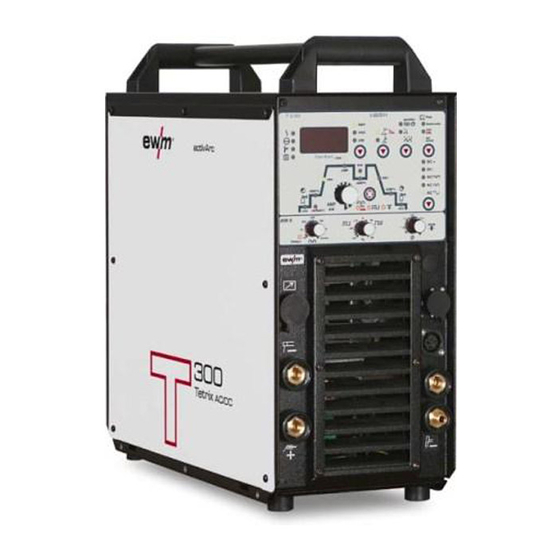
Page 14: Machine Description
Machine description TETRIX 270; 300 AC/DC COMFORT activArc Machine description TETRIX 270; 300 AC/DC COMFORT activArc 4.1.1 Front view Figure 4-1 Item No.: 099-004877-EWM01... - Page 15 Machine description TETRIX 270; 300 AC/DC COMFORT activArc Item Symbol Description Carrying handle Control / Operating elements (see chapter Function specification) Connection socket, 19-pole Remote control connection Cooling air inlet Connection socket, welding current “-” (with DC- polarity) connection for Electrode holder Connection socket, welding current “+”...
-
Page 16: Rear View
Machine description TETRIX 270; 300 AC/DC COMFORT activArc 4.1.2 Rear view Figure 4-2 Item No.: 099-004877-EWM01... - Page 17 Machine description TETRIX 270; 300 AC/DC COMFORT activArc Item Symbol Description 19-pole connection socket (option) Analogue interface for mechanised welding analog 7-pole connection socket (option) Wire feed unit connection (cold wire); RINT; Q-DOC, etc. digital G¼” connecting nipple Shielding gas connection on the pressure reducer Main switch, machine on/off Strain relief with mains connection cable 4-pole connection socket...
-
Page 18: Tetrix 350 Ac/Dc Comfort Activarc
Machine description TETRIX 350 AC/DC COMFORT activArc TETRIX 350 AC/DC COMFORT activArc 4.2.1 Front view Figure 4-3 Item No.: 099-004877-EWM01... - Page 19 Machine description TETRIX 350 AC/DC COMFORT activArc Item Symbol Description Carrying handle Control / Operating elements (see chapter Function specification) Connection socket, 8-pole / 12-pole 8-pole: TIG Up/Down or potentiometer torch control lead 12-pole: Control lead for TIG up/down torch with LED display (option) Connection socket, 5-pole Standard TIG torch control lead Cooling air inlet...
-
Page 20: Rear View
Machine description TETRIX 350 AC/DC COMFORT activArc 4.2.2 Rear view Figure 4-4 Item No.: 099-004877-EWM01... - Page 21 Machine description TETRIX 350 AC/DC COMFORT activArc Item Symbol Description 19-pole connection socket (option) Analogue interface for mechanised welding analog 7-pole connection socket (option) Wire feed unit connection (cold wire); RINT; Q-DOC, etc. digital 7-pole connection socket (option) Wire feed unit connection (cold wire); RINT; Q-DOC, etc. digital 9-pole D-SUB connection socket, serial PC interface Interface set SECINTX10 DSUB required (observe installation instructions)
-
Page 22: Tetrix 500 Ac/Dc Comfort Activarc
Machine description TETRIX 500 AC/DC COMFORT activArc TETRIX 500 AC/DC COMFORT activArc 4.3.1 Front view Figure 4-5 Item No.: 099-004877-EWM01... - Page 23 Machine description TETRIX 500 AC/DC COMFORT activArc Item Symbol Description Carrying handle Main switch, machine on/off Connection socket, 8-pole / 12-pole 8-pole: TIG Up/Down or potentiometer torch control lead 12-pole: Control lead for TIG up/down torch with LED display (option) Connection socket, 5-pole Standard TIG torch control lead Cooling air inlet...
-
Page 24: Rear View
Machine description TETRIX 500 AC/DC COMFORT activArc 4.3.2 Rear view Figure 4-6 Item No.: 099-004877-EWM01... - Page 25 Machine description TETRIX 500 AC/DC COMFORT activArc Item Symbol Description 7-pole connection socket (option) Wire feed unit connection (cold wire); RINT; Q-DOC, etc. digital 7-pole connection socket (option) Wire feed unit connection (cold wire); RINT; Q-DOC, etc. digital 9-pole D-SUB connection socket, serial PC interface Interface set SECINTX10 DSUB required (observe installation instructions) PC INT 8-pole connection socket...
-
Page 26: Functional Characteristics
Functional characteristics Machine control – Operating elements Functional characteristics Machine control – Operating elements Machine control provides the user with up to 8 welding tasks (JOBs). JOB "0" represents manual operating mode. This is where you can change/optimise all parameters directly in machine control (see chapter "Operating concepts"). Figure 5-1 Item Symbol Description... - Page 27 Functional characteristics Machine control – Operating elements Item Symbol Description “Welding current polarity” button Direct current welding with positive polarity on the electrode holder in relation to the workpiece (pole reversal switch, MMA only). DC welding with negative polarity on the torch (or stick electrode holder) in relation to the workpiece.
-
Page 28: Function Sequence
Functional characteristics Machine control – Operating elements 5.1.1.1 Function sequence Figure 5-2 Item Symbol Description “Select welding parameters” button This button is used to select the welding parameters depending on the welding process and operating mode used. Gas pre-flow time (TIG), absolute setting range 0.0 sec to 20.0 sec (0.1s increments). Ignition current (TIG) Hotstart current (MMA) AMP%... -
Page 29: Operating Concepts
Functional characteristics Operating concepts Item Symbol Description Pulse break time/slope time from AMP to AMP% • Pulse break setting range: 0.01 sec to 20.0 sec (0.01 sec increments < 0.5 sec; 0.1 sec increments > 0.5 sec) • Slope time (tS1) setting range: 0.0 sec to 20.0 sec (see chapter "Advanced settings"). -
Page 30: Manual, Standard Operation (Job 0)
Functional characteristics Operating concepts 5.2.1 Manual, standard operation (JOB 0) "Manual, standard operation (JOB 0)" is set by default on delivery and every time the machine control is reset. This means that the welder repeatedly makes all the required welding settings and re-adjusts them for each individual welding task. -
Page 31: Job Operation (Job 1 To 7)
Functional characteristics Operating concepts 5.2.2 JOB operation (JOB 1 to 7) You can select, change and save the required welding parameters for recurring welding tasks (JOBs) in up to 7 JOBs (JOB 1 to JOB 7). 5.2.2.1 Displaying and changing the JOB number Operating Action Result... -
Page 32: Welding Data Display
Functional characteristics Operating concepts 5.2.3 Welding data display The following welding parameters can be displayed before (nominal values) or during (actual values) welding. Parameter Before welding During welding (nominal values) (actual values) Welding current Welding voltage JOB number Parameter times Frequency, balance Parameter currents 5.2.3.1... -
Page 33: Tig Welding
Functional characteristics TIG welding TIG welding 5.3.1 Arc ignition 5.3.1.1 HF ignition Figure 5-3 The arc is started without contact from high-voltage ignition pulses. a) Position the welding torch in welding position over the workpiece (distance between the electrode tip and workpiece should be approx. -
Page 34: Optimising The Ignition Characteristics For Pure Tungsten Electrodes
Functional characteristics TIG welding 5.3.2 Optimising the ignition characteristics for pure tungsten electrodes The best ignition and stabilisation of the arc (DC, AC) and optimum spherical cup formation in the tungsten electrode depend on the electrode diameter being used. The set value should correspond to the diameter of the tungsten electrode. The value can of course be adjusted in line with different requirements. -
Page 35: Optimal And Fast Spherical Cup Formation
Functional characteristics TIG welding 5.3.5 Optimal and fast spherical cup formation A conically ground needle (approx. 35°) is generally required to form an ideal spherical cup. Spherical cup formation preset Operating Action Result Display element spotArc operating mode Switch off pulse welding Set spotArc time in line with the electrode diameter in use (refer to the table of guideline values for spherical cup formation depending on welding current) -
Page 36: Tig Function Sequences / Operating Modes
Functional characteristics TIG welding 5.3.6 TIG function sequences / operating modes The "Select welding parameter" button and the "Welding parameter setting" rotary transducer can be used to control all the parameters for the TIG process: Pos. Description “Select welding parameters” button “Welding parameter setting”... -
Page 37: Tig Non-Latched Operation
Functional characteristics TIG welding 5.3.6.2 TIG non-latched operation When the foot-operated remote control RTF is connected, the machine switches automatically to non-latched operation. The up- and down-slopes are switched off. Figure 5-6 Step 1: • Press and hold torch trigger 1. •... -
Page 38: Tig Latched Operation
Functional characteristics TIG welding 5.3.6.3 TIG latched operation When the foot-operated remote control RTF is connected, the machine switches automatically to non-latched operation. The up- and down-slopes are switched off. AMP% start Down Figure 5-7 Step 1 • Press torch trigger 1, the gas pre-flow time elapses. •... -
Page 39: Tig Spotarc
Functional characteristics TIG welding 5.3.6.4 TIG spotArc The TIG SpotArc function is activated with the pulse variant automated frequencies by default, because this combination produces the most effective results. The user can of course combine the function with other pulse variants depending on the selected welding process. Pulse time (t1) and pulse break time (t2) can be set independently, but the spot time (tP) should be much greater than the pulse time in order to achieve an appropriate result. - Page 40 Functional characteristics TIG welding Figure 5-8 Sequence: • Press and hold torch trigger 1. • The gas pre-flow time elapses. • HF ignition pulses jump from the electrode to the workpiece, the arc ignites. • The welding current flows and immediately assumes the value set for the ignition current I start •...
- Page 41 Functional characteristics TIG welding Setting instructions for spotArc for CrNi panels Butt weld Automated pulses 0.3s 100A 0.5s Fast pulsing (2.5kHz) 0.3s 100A 0.5s Fast pulsing (2.5kHz) with activArc 0.35s 180A 0.7s Fillet weld Automated pulses with activArc 0.5s 150A 0.1s Fast pulsing (2.5kHz) with activArc 0.5s...
-
Page 42: Tig Non-Latched Operation, C Version
Functional characteristics TIG welding 5.3.6.5 TIG non-latched operation, C version This operating mode needs to be activated (see chapter "Advanced settings" in the "TIG non- latched operating mode, C version") section. Figure 5-9 1st cycle • Press torch trigger 1, the gas pre-flow time elapses. •... -
Page 43: Tig Pulses, Function Sequences
Functional characteristics TIG welding 5.3.7 TIG pulses, function sequences The function sequences in pulses basically behave in the same way as in standard welding, but during the main current phase there is a continual switching back and forth between the pulse and pause currents at the relevant times. -
Page 44: Tig Pulse Variants
Functional characteristics TIG welding 5.3.8 TIG pulse variants The machines have an integrated pulse device. With pulses, the machine switches back and forth between the pulse current (main current) and pause current (secondary current). 5.3.8.1 Pulses (thermal pulses) With thermal pulses, the pulse and pause times (frequency up to 200 Hz) and the pulse edges (ts1 and ts2) are entered in seconds on the control. -
Page 45: Khz Pulses (Metallurgic Pulses)
Functional characteristics TIG welding 5.3.8.2 KHz pulses (metallurgic pulses) The kHz pulses (metallurgic pulses) use the plasma pressure produced at high currents (arc pressure) which is used to achieve a constricted arc with concentrated heat feeding. The frequency can be infinitely adjusted from 50 Hz to 2.5 kHz and the pulse balance from 1 –... -
Page 46: Ac Special
Functional characteristics TIG welding 5.3.8.4 AC special Application: e.g. for welding thick metal sheets onto thin metal sheets. Operating Action Result element Select TIG AC special Press the "TIG pulses" button until the signal light comes on special AC current phase pulse current AMP% = DC phase pulse pause current Pulse time;... -
Page 47: Tig Activarc Welding
5.3.9 TIG activArc welding The EWM activArc process, thanks to the highly dynamic controller system, ensures that the power supplied is kept virtually constant in the event of changes in the distance between the welding torch and the weld pool, e.g. during manual welding. Voltage losses as a result of a shortening of the distance between the torch and molten pool are compensated by a current rise (ampere per volt - A/V), and vice versa. -
Page 48: 5.3.10 Tig Shielding Gas Setting
Functional characteristics TIG welding 5.3.10 TIG shielding gas setting 5.3.10.1 Gas test Operating Action Result element Press the "Select welding parameter" button until the "activArc" LED flashes. Press the "Select welding parameter" button and hold for approx. 5 sec. 5 sec. The gas pre-flow time LED (TIG) will come on, shielding gas flows for approx. -
Page 49: 5.3.12 Torch Mode And Up/Down Speed Setting
Functional characteristics TIG welding 5.3.12 Torch mode and up/down speed setting Only the modes listed are suitable for the corresponding torch types. The user has the modes 1-6 and modes 11-16 available. Modes 11-16 include the same function options as 1-6, but without a tapping function (see chapter “Tapping operating mode”) for the secondary current. The function options in the individual modes can be found in the tables on the torch types. -
Page 50: Standard Tig Torch (5-Pole)
Functional characteristics TIG welding 5.3.12.1 Standard TIG torch (5-pole) Standard torch with one torch trigger: Diagram Operating Explanation of symbols elements BRT1 = Torch trigger 1 (welding current on/off; secondary current via tapping function) Functions mode Operating elements BRT 1 Welding current On/Off (factory-set) BRT 1... - Page 51 Functional characteristics TIG welding Standard torch with one rocker (MG rocker, two torch triggers) Diagram Operating Explanation of symbols elements BRT 1 = torch trigger 1 BRT 2 = torch trigger 2 Functions mode Operating elements BRT 1 Welding current On/Off Secondary current BRT 2 (factory-set)
-
Page 52: Tig Up/Down Torch (8-Pole)
Functional characteristics TIG welding 5.3.12.2 TIG up/down torch (8-pole) Up/down torch with one torch trigger Diagram Operating Explanation of symbols elements TT 1 = torch trigger 1 Functions Mode Operating elements BRT 1 Welding current on/off BRT 1 Secondary current (tapping mode) (factory- set) Increase welding current, infinite adjustment (up function) - Page 53 Functional characteristics TIG welding Up/down torch with two torch triggers Diagram Operating Explanation of symbols elements TT 1 = torch trigger 1 (left) TT 2 = torch trigger 2 (right) Functions Mode Operating elements BRT 1 Welding current on/off BRT 2 Secondary current BRT 1 (factory-...
-
Page 54: Potentiometer Torch (8-Pole)
Functional characteristics TIG welding 5.3.12.3 Potentiometer torch (8-pole) The welding machine needs to be configured for operation with a potentiometer torch (see chap. "Configuring TIG potentiometer torch") Potentiometer torch with one torch trigger: Diagram Operating Explanation of symbols elements BRT 1 = torch trigger 1 Functions Mode Operating... -
Page 55: Retox Tig Torch (12-Pole)
Functional characteristics TIG welding 5.3.12.4 RETOX TIG torch (12-pole) The welding machine must be fitted with the 12-pole torch connection socket (option). Diagram Pictogram Explanation of symbols = Torch trigger 1 (welding current on/off; secondary current via tapping function) = Torch trigger 2 (secondary current) Up/down = Increase/reduce welding current = Job switching Additional functions (modes 4-6) are generally selected by a brief tap on TT 2. -
Page 56: 5.3.13 Setting The First Increment
Functional characteristics TIG welding 5.3.13 Setting the first increment Figure 5-14 This function is only available when using up/down torches in modes 4 and 14. Operating Action Result Display element Switch off the welding machine Press and hold key button Switch on welding machine Select Torch mode menu item "trd"... -
Page 57: Mma Welding
Functional characteristics MMA welding MMA welding Once the MMA welding process is selected, there is open circuit voltage present on the welding current sockets and on the G1/4” shielding gas connection on the front of the machine. Attach the yellow protective cap onto the G1/4” shielding gas connection on the front of the machine. -
Page 58: Hotstart Time
Functional characteristics Key switch 5.4.2.2 Hotstart time Operating Action Result Displays element Select hotstart time welding parameter Press until hotstart time light comes on Set hotstart time 5.4.3 Arcforcing Shortly before the electrode threatens to stick, the arcforcing device sets an increased current designed to prevent the electrode sticking. -
Page 59: Advanced Settings
Functional characteristics Advanced settings Advanced settings 5.6.1 Setting slope times for secondary current AMP% or pulse edges Figure 5-15 Operating Action Result Display element Select slope time tS1 2 sec. Set slope time tS1 from main current AMP% to secondary current AMP Select slope time tS2 Set slope time tS2 from secondary current AMP% to main current AMP... -
Page 60: Tig Non-Latched Operating Mode, C Version
Functional characteristics Advanced settings 5.6.2 TIG non-latched operating mode, C version Operating Action Result Display element Switch off the welding machine Press and hold key button Switch on the welding machine Select Configuration menu item "cFG" The parameter that can be changed and the associated value blink alternately in the display. Hold until menu item "2tc"... -
Page 61: Configuring The Tig Potentiometer Torch Connection
Functional characteristics Advanced settings 5.6.3 Configuring the TIG potentiometer torch connection When connecting a potentiometer torch, jumper JP27 on PCB T320/1 inside the welding machine should be unplugged. Welding torch configuration Setting Prepared for TIG standard or up/down torch (factory setting) JP27 Prepared for potentiometer torches JP27... -
Page 62: Selection And Adjustment
Functional characteristics Advanced settings 5.6.4.1 Selection and adjustment Operating Action Result Display element Switch off the welding machine Press and hold key button Switch on welding machine Select Configuration menu item "cFG" The parameter that can be changed and the associated value blink alternately in the display. Hold until "SEt"... -
Page 63: Remote Control
Functional characteristics Remote control Remote control Only the remote controls described in these operating instructions may be connected. Only plug the remote control into the remote control socket and lock when the machine is switched off. The remote control is detected automatically when the welding machine is switched on. 5.7.1 Foot-operated remote control RTF 1 Functions... -
Page 64: Manual Remote Control Rtp 2
Functional characteristics Remote control 5.7.5 Manual remote control RTP 2 Functions • TIG / MMA • Infinitely adjustable welding current (0% to 100%) depending on the preselected main current on the welding machine. • Pulse / spot / normal • Frequency and spot times infinitely adjustable. -
Page 65: Interfaces For Automation
Functional characteristics Interfaces for automation Interfaces for automation The welding power sources feature a very high standard of safety. This safety standard is also maintained when peripheral equipment is connected for automatic welding if this peripheral equipment fulfils the same criteria, particularly with regard to isolation from the mains supply. -
Page 66: Remote Control Connection Socket, 19-Pole
Functional characteristics Interfaces for automation 5.8.2 Remote control connection socket, 19-pole If the machine is operated using control voltages, the connection should be made via isolating amplifiers! To control the main or secondary current via control voltages, the relevant inputs must be enabled (activation of control voltage specification). -
Page 67: Commissioning
Commissioning General Commissioning General Warning – Risk from electrical current! Follow the safety instructions on the opening pages entitled “For your safety”. Connection and welding leads (e.g. electrode holder, welding torch, workpiece lead, interfaces) may only be connected when the machine is switched off. Re-fit protective caps onto sockets and cable plugs when not in use! Area of application –... -
Page 68: Tig Welding
Commissioning TIG welding TIG welding 6.7.1 Welding torch connection We can only guarantee the perfect functioning of our machines when used with our range of welding torches. The welding torches being used must meet the following conditions (see also the operating instructions for the torch): •... -
Page 69: Torch Connection Options And Pin Assignments
Commissioning TIG welding Prepare welding torch according to the welding task in hand (see operating instructions for the torch). • Insert the welding current plug on the welding torch into the welding current connection socket and lock by turning to the right. •... -
Page 70: Shielding Gas Supply (Shielding Gas Cylinder For Welding Machine)
Commissioning TIG welding 6.7.4 Shielding gas supply (shielding gas cylinder for welding machine) 6.7.4.1 Connecting the shielding gas supply No dirt must be allowed to enter the shielding gas supply, as this would cause blockages in the shielding gas supply. All shielding gas connections must be gastight. -
Page 71: Mma Welding
Commissioning MMA welding MMA welding 6.8.1 Electrode holder connection There is an open circuit voltage or welding voltage on the G1/4” connecting nipple for shielding gas (front of the machine). If welding is carried out alternately using TIG and MMA welding and if a welding torch and an electrode holder are connected to the machine, the open-circuit or welding voltage is applied simultaneously to both. -
Page 72: Connection For Workpiece Lead
Commissioning Cooling unit function specification 6.8.2 Connection for workpiece lead • Insert cable plug of the workpiece lead into either the "+" or "-" welding current connection socket and lock by turning to the right. Polarity depends on the instructions from the electrode manufacturer given on the electrode packaging. -
Page 73: 6.10.1.1 Selection And Adjustment
Commissioning PC interface 6.10.1.1 Selection and adjustment Operating Action Result element Select JOB numberSignal light comes on Select JOB "0" (synchronisation takes place in JOB 0 only) Select AC welding with corresponding current output wave Square current output wave form Trapezoidal current output wave form Sinusoidal current output wave form Turn the "Alternating current frequency (TIG AC)"... -
Page 74: Maintenance And Testing
DIN EN 61010-1 Appendix A – Measuring Circuit A1. You as the user are tasked with ensuring that your EWM machines conform to the standard IEC/DIN EN 60974-4 and are tested with the relevant test equipment and measuring devices given above. -
Page 75: Scope Of The Test
Maintenance and testing Test 7.3.2 Scope of the test a) Visual inspection b) Electrical test: measurement of • open circuit voltage • insulation resistance, or alternatively • leakage currents • protective conductor resistance c) Functional test d) Documentation 7.3.3 Visual inspection The key areas in the test are: 1. -
Page 76: Measuring The Leakage Current (Protective Conductor And Contact Current)
Note: Even if the leakage current measurement according to the standard is only an alternative to the insulation resistance measurement, EWM recommends always performing both measurements, especially following repair work. The leakage current is based for the greater part on a physical effect other than the insulation resistance. -
Page 77: Repair Work
Returns of defective equipment subject to warranty may only be made through your EWM sales partner. In the event of problems or queries, please contact the EWM Service Department directly (+49 (0) 2680 181 0). Use only genuine spare parts and replacement parts when replacing. When placing an order, please quote the type designation and item number, as well as the type, serial number and item number of the relevant equipment. -
Page 78: Disposing Of Equipment
Your administrative office will be pleased to inform you of the options. EWM participates in an approved waste disposal and recycling system and is registered in the Used Electrical Equipment Register (EAR) under number WEEE DE 57686922. -
Page 79: Warranty
• Wire feeds • Cooling units • Trolleys * If these are operated with genuine EWM accessories (such as intermediate tube package, remote control, remote control extension cable, coolant, etc.). 1-year warranty on: • Used EWM machines • Automation and mechanisation components •... -
Page 80: Warranty Declaration
This limitation does not apply to personal injuries or damage to property caused by negligent behaviour on the part of EWM. In no way will EWM be responsible for lost profits, indirect or subsequent damage. EWM is not liable for damages based on the claims of third parties. -
Page 81: Operating Problems, Causes And Remedies
Operating problems, causes and remedies Error messages (power source) Operating problems, causes and remedies All machines are subject to rigorous production checks and final checks. If despite this, anything fails to work at any time, please check the machine using the following chart. If none of the fault rectification procedures described leads to the correct functioning of the machine, please inform your authorised dealer. -
Page 82: Accessories, Options
Accessories, options General accessories Accessories, options 10.1 General accessories Type Designation Item number KF 23E-10 Coolant (-10 °C), 10 litres 094-000530-00000 KF 23E-10 Coolant (-10 °C), 10 litres 094-000530-00000 KF 37E-10 Coolant (-20 °C), 10 litres 094-006256-00000 DM1 32L/MIN Manometer pressure reducer 094-000009-00000 G1 G1/4 R 2M Gas hose... -
Page 83: Transport Vehicle
Accessories, options Transport vehicle 10.5 Transport vehicle Type Description / Name Item number TROLLY 75 B1 Transport vehicle disassembled, boxed, for power 090-008176-00000 source + 1 module + 1 gas cylinder 10.6 Cooling units Type Description Item number COOL35 U30 Air cooling unit (TETRIX 270) 090-008196-00102 COOL71 U42... -
Page 84: Circuit Diagrams
Circuit diagrams TETRIX 270 AC/DC COMFORT activArc Circuit diagrams Original format circuit diagrams are located inside the machine. 11.1 TETRIX 270 AC/DC COMFORT activArc Stecker X3 D-SUB 15polig X8/1 X8/2 D-Sub. D-Sub. D-Sub. D-Sub. 15polig 15polig 15polig 15polig 20VAC X5/1... - Page 85 Circuit diagrams TETRIX 270 AC/DC COMFORT activArc D-Sub. 15polig X12/1 X14/1 Relais IGRO +15V X14/2 Poti-IH X12/2 X14/3 Poti-IL X12/3 X12/4 X14/4 Polwendung PWS X14/5 Uref.10V X12/5 42VAC X14/6 Isoll X12/6 0VAC X12/7 X14/7 Puls Frequenz X12/8 X14/8 X14/9 +15V...
-
Page 86: Tetrix 300 Ac/Dc Comfort Activarc
Circuit diagrams TETRIX 300 AC/DC COMFORT activArc 11.2 TETRIX 300 AC/DC COMFORT activArc Stecker X3 D-SUB 15polig X8/1 X8/2 D-Sub. D-Sub. D-Sub. D-Sub. 15polig 15polig 15polig 15polig 20VAC X5/1 0VAC X5/2 X4/1 Figure 11-3 Item No.: 099-004877-EWM01... - Page 87 Circuit diagrams TETRIX 300 AC/DC COMFORT activArc D-Sub. 15polig X14/1 Relais IGRO X12/1 +15V X14/2 X12/2 Poti-IH X12/3 X14/3 Poti-IL X12/4 X14/4 Polwendung PWS X14/5 Uref.10V X12/5 42VAC X14/6 X12/6 Isoll 0VAC X12/7 X14/7 Puls Frequenz X12/8 X14/8 X14/9 +15V X12/9 HF-Liftarc X12/10...
-
Page 88: Tetrix 350 Ac/Dc Comfort Activarc
Circuit diagrams TETRIX 350 AC/DC COMFORT activArc 11.3 TETRIX 350 AC/DC COMFORT activArc Stecker X3 D-SUB 15polig X8/1 X8/2 D-Sub. D-Sub. D-Sub. D-Sub. 15polig 15polig 15polig 15polig X5/1 20VAC X5/2 0VAC X4/1 Figure 11-5 Item No.: 099-004877-EWM01... - Page 89 Circuit diagrams TETRIX 350 AC/DC COMFORT activArc D-Sub. 9polig X12/1 X14/1 Relais IGRO +15V X14/2 Poti-IH X12/2 X14/3 Poti-IL X12/3 X12/4 X14/4 Polwendung PWS X14/5 Uref.10V X12/5 42VAC X14/6 Isoll X12/6 0VAC X12/7 X14/7 Puls Frequenz X12/8 X14/8 X14/9 +15V X12/9 HF-Liftarc X14/10...
-
Page 90: Tetrix 500 Ac/Dc Comfort Activarc
Circuit diagrams TETRIX 500 AC/DC COMFORT activArc 11.4 TETRIX 500 AC/DC COMFORT activArc X8/1 X8/2 D-Sub. D-Sub. D-Sub. D-Sub. 15polig 15polig 15polig 15polig T x x - 1 n = ? W d g . X5/1 20VAC X5/2 0VAC X4/1 T x x n = ? W d g . - Page 91 Circuit diagrams TETRIX 500 AC/DC COMFORT activArc D-Sub. 9polig X14/1 Relais IGRO X12/1 +15V X12/2 X14/2 Poti-IH X12/3 X14/3 Poti-IL X14/4 Polwendung PWS X12/4 X14/5 X12/5 Uref.10V 42VAC X12/6 X14/6 Isoll 0VAC X14/7 Puls Frequenz X12/7 X14/8 X12/8 X14/9 X12/9 +15V HF-Liftarc X12/10...
-
Page 92: Declaration Of Conformity
Umbauten, die nicht ausdrücklich von authorised by EWM. bées n’ayant pas été autorisés expressé- EWM autorisiert sind, verliert diese ment par EWM, cette déclaration devient Erklärung ihre Gültigkeit. caduque. Gerätebezeichnung: Description of the machine: Déscription de la machine: Gerätetyp:...
Need help?
Do you have a question about the TETRIX 270 AC/DC COMFORT activArc and is the answer not in the manual?
Questions and answers