
Related Manuals for EWM Saturn 301 FKG


Summary of Contents for EWM Saturn 301 FKG
- Page 1 Operating instructions Welding machine Saturn 301 FKG (M1.02 / M2.20 / M2.40) Saturn 351 FKG (M1.02 / M2.20 / M2.40) 099-004968-EW501 Observe additional system documents! 13.09.2021...
- Page 2 +49 2680 181-0. A list of authorised sales partners can be found at www.ewm-group.com/en/specialist-dealers. Liability relating to the operation of this equipment is restricted solely to the function of the equipment. No other form of liability, regardless of type, shall be accepted.
-
Page 3: Table Of Contents
Contents Notes on using these operating instructions Contents 1 Contents ............................3 2 For your safety ..........................6 Notes on using these operating instructions ................6 Explanation of icons ....................... 7 Safety instructions ........................8 Transport and installation ....................11 3 Intended use .......................... - Page 4 Contents Notes on using these operating instructions 5.1.11.3 Non-latched mode ................. 42 5.1.11.4 Latched mode ..................43 5.1.11.5 Spot welding ..................44 5.1.11.6 Interval ....................45 6 Maintenance, care and disposal ....................46 General..........................46 6.1.1 Cleaning ........................ 46 6.1.2 Dirt filter.........................
- Page 5 Contents Notes on using these operating instructions 099-004968-EW501 13.09.2021...
-
Page 6: For Your Safety
For your safety Notes on using these operating instructions For your safety Notes on using these operating instructions DANGER Working or operating procedures which must be closely observed to prevent imminent serious and even fatal injuries. • Safety notes include the "DANGER" keyword in the heading with a general warning symbol. •... -
Page 7: Explanation Of Icons
For your safety Explanation of icons Explanation of icons Symbol Description Symbol Description Indicates technical aspects which the u- Activate and release / Tap / Tip ser must observe. Switch off machine Release Switch on machine Press and hold Switch Incorrect / Invalid Turn Correct / Valid... -
Page 8: Safety Instructions
For your safety Safety instructions Safety instructions WARNING Risk of accidents due to non-compliance with the safety instructions! Non-compliance with the safety instructions can be fatal! • Carefully read the safety instructions in this manual! • Observe the accident prevention regulations and any regional regulations! •... - Page 9 For your safety Safety instructions WARNING Risk of injury due to improper clothing! During arc welding, radiation, heat and voltage are sources of risk that cannot be avoided. The user has to be equipped with the complete personal protective equipment at all times.
- Page 10 For your safety Safety instructions CAUTION Smoke and gases! Smoke and gases can lead to breathing difficulties and poisoning. In addition, solvent vapour (chlorinated hydrocarbon) may be converted into poisonous phosgene due to the ultraviolet radiation of the arc! • Ensure that there is sufficient fresh air! •...
-
Page 11: Transport And Installation
For your safety Transport and installation CAUTION Obligations of the operator! The respective national directives and laws must be complied with when operating the machine! • Implementation of national legislation relating to framework directive 89/391/EEC on the int- roduction of measures to encourage improvements in the safety and health of workers at work and associated individual guidelines. - Page 12 For your safety Transport and installation CAUTION Risk of accidents due to supply lines! During transport, attached supply lines (mains leads, control cables, etc.) can cause risks, e.g. by causing connected machines to tip over and injure persons! • Disconnect all supply lines before transport! Risk of tipping! There is a risk of the machine tipping over and injuring persons or being damaged itself during movement and set up.
-
Page 13: Intended Use
3.2.1 Warranty For more information refer to the "Warranty registration" brochure supplied and our information regarding warranty, maintenance and testing at www.ewm-group.com! 3.2.2 Declaration of Conformity This product corresponds in its design and construction to the EU directives listed in the decla- ration. -
Page 14: Machine Description - Quick Overview
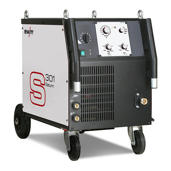
Machine description – quick overview Front view / side view from the right Machine description – quick overview Front view / side view from the right Figure 4-1 099-004968-EW501 13.09.2021... - Page 15 Machine description – quick overview Front view / side view from the right Item Symbol Description Welding voltage step switch To set the welding voltage Main Switch Switching the machine on or off. Signal light, Functional error On when excess temperature detected Connection socket, workpiece lead "Hard"...
-
Page 16: Rear View / Interior View From The Right
Machine description – quick overview Rear view / interior view from the right Rear view / interior view from the right Figure 4-2 099-004968-EW501 13.09.2021... - Page 17 Machine description – quick overview Rear view / interior view from the right Item Symbol Description Securing elements for shielding gas cylinder (strap/chain) Cooling air outlet Bracket for shielding gas cylinder Carrying handle Operating elements > see 4.3.1.1 chapter Wire feed unit Wire spool holder Connection thread - G¼"...
-
Page 18: Machine Control - Operating Elements
Machine description – quick overview Machine control – Operating elements Machine control – Operating elements 4.3.1 Welding machine control M1.02 Figure 4-3 Item Symbol Description Ready for operation signal light Signal light on when the machine is switched on and ready for operation Rotary dial, Wire speed setting Infinite adjustment of the wire speed. -
Page 19: Internal Operating Elements
Machine description – quick overview Machine control – Operating elements 4.3.1.1 Internal operating elements The maximum possible machine configuration is given in the text description. If necessary, the optional connection may need to be retrofitted > see 9 chapter. • Unlock the right-hand cover on the machine. -
Page 20: M2.20 Welding Machine Control
Machine description – quick overview Machine control – Operating elements 4.3.2 M2.20 welding machine control Figure 4-5 Item Symbol Description Upper, display Displays welding voltage or person who designated the runtime parameters Signal light, HOLD Lit: Display shows the last parameters used for welding. Not lit: Display shows the setpoint values or current values during welding. -
Page 21: Setting The Operating Point (Welding Output)
Machine description – quick overview Machine control – Operating elements Item Symbol Description Wire feed speed/welding parameter rotary knob Infinite adjustment of the wire feed speed/welding parameters and corresponding va- lues Gas test push-button > see 5.1.5.3 chapter Wire inching push-button For potential- and gas-free inching of the wire electrode through the hose package to the welding torch. -
Page 22: Explanation Of Symbols
Machine description – quick overview Machine control – Operating elements Select expert parameters: Gas pre-flow time "GvS" (0 s to 10 s) Wire creep speed "On" 0.5 – 24 m/min Ignition time "tZn" (0 ms to 500 ms) The selected parameter is shown on the display. Set the parameter chosen. -
Page 23: Welding Parameter Ignition Time "Tzn" Diagram
Machine description – quick overview Machine control – Operating elements 4.3.2.5 Welding parameter ignition time "tZn" diagram The arc striking is positively affected by the adjustable ignition time. After the arc striking, the wire feeder continues operating in wire creep speed for the set ignition time. This behaviour occurs whenever the pause time between the welding operations is at least 1.5 seconds. -
Page 24: M2.40 Welding Machine Control
Machine description – quick overview Machine control – Operating elements 4.3.3 M2.40 welding machine control Figure 4-7 Item Symbol Description Signal light Voltage On when the welding voltage or open circuit voltage is displayed. Signal light, Wire correction On when the correction value of the wire speed is being displayed. Signal light, MANUAL Signal light is on when the machine is not in JOB mode. - Page 25 Machine description – quick overview Machine control – Operating elements Item Symbol Description Operating mode button ---------- Non-latched ------- Latched ----- Spots ----- Interval Sequence parameter push-button --------- Gas post-flow time ------- Wire burn-back ------ Spot time/pulse time -------- Pulse pause Signal light, Choke tappings Depending on the machine design, there are two or three workpiece connection sock- ets on the welding machine (choke tappings).
-
Page 26: Welding Task Selection
Machine description – quick overview Machine control – Operating elements 4.3.3.1 Welding task selection This microprocessor-controlled control works according to the one-dial operation principle. Only the gas type, material type and wire electrode diameter should be set as the JOB number on the control, as well as welding output via the step switch. -
Page 27: Setting The Operating Point (Welding Output)
Machine description – quick overview Machine control – Operating elements 4.3.3.2 Setting the operating point (welding output) The operating point setting in JOB "0" (manual) is carried out as described in the chapter of the same name for control M2.4x. The following settings are therefore only intended for work in JOBs 1-24. -
Page 28: Setting The Expert Parameters
Machine description – quick overview Machine control – Operating elements 4.3.3.5 Setting the expert parameters The parameters are pre-set in the control but can be adjusted individually. If there is no user action within 5 seconds during the setting process, the control interrupts the process and switches back to the standard display. -
Page 29: Welding Parameter Ignition Time "Tzn" Diagram
Machine description – quick overview Machine control – Operating elements 4.3.3.7 Welding parameter ignition time "tZn" diagram The arc striking is positively affected by the adjustable ignition time. After the arc striking, the wire feeder continues operating in wire creep speed for the set ignition time. This behaviour occurs whenever the pause time between the welding operations is at least 1.5 seconds. -
Page 30: Design And Function
Design and function Transport and installation Design and function WARNING Risk of injury from electrical voltage! Contact with live parts, e.g. power connections, can be fatal! • Observe the safety information on the first pages of the operating instructions! • Commissioning must be carried out by persons who are specifically trained in handling power sources! •... -
Page 31: Lifting By Crane
Design and function Transport and installation 5.1.2 Lifting by crane WARNING Risk of injury during lifting by crane When lifting the machine by crane, persons may be severely injured by falling machines or mount-on components. • Simultaneous lifting of system components such as power source wire feeder or cooling unit without suitable crane components is not allo- wed. -
Page 32: Shielding Gas Supply (Shielding Gas Cylinder For Welding Machine)
Design and function Transport and installation 5.1.5 Shielding gas supply (shielding gas cylinder for welding machine) WARNING Risk of injury due to improper handling of shielding gas cylinders! Improper handling and insufficient securing of shielding gas cylinders can cause serious injuries! •... -
Page 33: Shielding Gas Hose Connection
Design and function Transport and installation 5.1.5.2 Shielding gas hose connection Figure 5-2 Item Symbol Description Connection thread - G¼" Shielding gas connection (inlet) • Screw the gas hose connection to the shielding gas connection (inlet) on the machine gas-tight. 5.1.5.3 Setting the shielding gas volume (gas test)/rinse hose package •... -
Page 34: Notes On The Installation Of Welding Current Leads
Design and function Transport and installation 5.1.6 Notes on the installation of welding current leads • Incorrectly installed welding current leads can cause faults in the arc (flickering). • Lay the workpiece lead and hose package of power sources without HF igniter (MIG/MAG) for as long and as close as possible in parallel. -
Page 35: Stray Welding Currents
Design and function Transport and installation 5.1.7 Stray welding currents WARNING Risk of injury due to stray welding currents! Stray welding currents can destroy protective earth conductors, damage machines and electronic devices and cause overheating of components, leading to fire. •... -
Page 36: Mains Connection
Design and function Transport and installation 5.1.8 Mains connection DANGER Hazards caused by improper mains connection! An improper mains connection can cause injuries or damage property! • The connection (mains plug or cable), the repair or voltage adjustment of the device must be carried out by a qualified electrician in accordance with the respective local laws or nati- onal regulations! •... -
Page 37: Welding Torch And Workpiece Line Connection
Design and function Transport and installation 5.1.9 Welding torch and workpiece line connection Prepare welding torch according to the welding task in hand (see operating instructions for the torch). Figure 5-8 Item Symbol Description Workpiece Connection socket, workpiece lead "Hard" choke tapping Connection socket, workpiece lead "Medium"... -
Page 38: Wire Feed
Design and function Transport and installation 5.1.10 Wire feed CAUTION Risk of injury due to moving parts! The wire feeders are equipped with moving parts, which can trap hands, hair, clothing or tools and thus injure persons! • Do not reach into rotating or moving parts or drive components! •... -
Page 39: Changing The Wire Feed Rollers
Design and function Transport and installation Figure 5-10 Observe the unwinding direction of the wire spool. 5.1.10.2 Changing the wire feed rollers Poor welding results due to faulty wire feeding! Wire feed rolls must be suitable for the diameter of the wire and the material. - Page 40 Design and function Transport and installation Figure 5-12 Item Symbol Description Feed roll tensioner Fixing the clamping unit and setting the pressure. Clamping unit Knurled screw Pressure roller Wire feed nipple Drive roller "Undetachable" knurled screws Guide tube Wire return nipple •...
-
Page 41: Spool Brake Setting
Design and function Transport and installation 5.1.10.4 Spool brake setting Figure 5-13 Item Symbol Description Allen screw Securing the wire spool retainer and adjustment of the spool brake • Tighten the Allen screw (8 mm) in the clockwise direction to increase the braking effect. Tighten the spool brake until the wire spool no longer turns when the wire feed motor stops but without it jamming during operation! 5.1.11 Operating modes (functional sequences) -
Page 42: Automatic Cut-Out
Design and function Transport and installation 5.1.11.2 Automatic cut-out The welding machine ends the ignition process or the welding process with an • Ignition fault (no welding current flows within 5 s after the start signal). • Arc interruption (arc is intrerupted for longer than 2 s). 5.1.11.3 Non-latched mode Figure 5-14 Step 1... -
Page 43: Latched Mode
Design and function Transport and installation 5.1.11.4 Latched mode Figure 5-15 Step 1 • Press and hold torch trigger. • Shielding gas is expelled (gas pre-flows). • Wire feed motor runs at "creep speed". • Arc ignites when the wire electrode makes contact with the workpiece; welding current flows. •... -
Page 44: Spot Welding
Design and function Transport and installation 5.1.11.5 Spot welding Figure 5-16 1. Start • Press and hold torch trigger. • Shielding gas is expelled (gas pre-flows). • Wire feed motor runs at "creep speed". • Arc ignites after the wire electrode makes contact with the workpiece; welding current flows. •... -
Page 45: Interval
Design and function Transport and installation 5.1.11.6 Interval Figure 5-17 1. Start • Press and hold torch trigger. • Shielding gas is expelled (gas pre-flows). • Wire-feed motor runs at "creep-start speed". • Arc ignites after the wire electrode makes contact with the workpiece; welding current flows. •... -
Page 46: Maintenance, Care And Disposal
Maintenance, care and disposal General Maintenance, care and disposal General DANGER Risk of injury due to electrical voltage after switching off! Working on an open machine can lead to fatal injuries! Capacitors are loaded with electrical voltage during operation. Voltage remains present for up to four minutes after the mains plug is removed. -
Page 47: Maintenance Work, Intervals
A periodic test according to IEC 60974-4 "Periodic inspection and test" has to be carried out. In addition to the regulations on testing given here, the relevant local laws and regulations must also be observed. For more information refer to the "Warranty registration" brochure supplied and our information regarding warranty, maintenance and testing at www.ewm-group.com! 099-004968-EW501 13.09.2021... -
Page 48: Disposing Of Equipment
• Information about returning used equipment or about collections can be obtained from the respective municipal administration office. • In addition to this, returns are also possible throughout Europe via EWM sales partners. 099-004968-EW501 13.09.2021... -
Page 49: Rectifying Faults
Rectifying faults Checklist for rectifying faults Rectifying faults All products are subject to rigorous production checks and final checks. If, despite this, something fails to work at any time, please check the product using the following flowchart. If none of the fault rectification procedures described leads to the correct functioning of the product, please inform your authorised dea- ler. -
Page 50: Check The Machine Type Setting
Switch on the welding machine; the display shows “Anl”. With “Anl” on the display, set the machine type: 0 ---------- Saturn 251 FKG 1 ---------- Saturn 301 FKG 2 ---------- Saturn 351 FKG 3 ---------- all decompact (DK, DG FDG, FDW) -
Page 51: Resetting The Control (Reset All)
Rectifying faults Resetting the control (Reset all) Resetting the control (Reset all) M2.xx control: The first action should always be to check and if necessary correct the machine type setting. All user settings will be overwritten with factory settings and must therefore be checked afterwards, or set up again! After resetting the machine control to the factory settings, it is essential that the machine type used is checked and reset if necessary. -
Page 52: Technical Data
Technical data Saturn 301 Technical data Performance specifications and guarantee only in connection with original spare and replacement parts! Saturn 301 Welding current (I 30 A to 300 A Welding voltage according to standard (U 15,5 V to 29 V Duty cycle DC at 40°... -
Page 53: Saturn 351
Technical data Saturn 351 Saturn 351 Welding current (I 30 A to 350 A Welding voltage according to standard (U 15,5 V to 31,5 V Duty cycle DC at 40° C 45 % 350 A 60 % 250 A 100 % 220 A Open circuit voltage (U 15,5 V to 41 V... -
Page 54: Accessories
Accessories Options Accessories Performance-dependent accessories like torches, workpiece leads, electrode holders or intermediate hose packages are available from your authorised dealer. Options Type Designation Item no. ON Filter F.0004 Retrofit option, dirt filter for air inlet 092-002090-00000 ON FSB WHEELS S Retrofit option for locking brake for machine wheels 092-002109-00000 ON Drahteinschleich Poti Retrofit option, wire creep rotary dial... -
Page 55: Replaceable Parts
Replaceable parts Wire feed rollers Replaceable parts Performance specifications and guarantee only in connection with original spare and replacement parts! 10.1 Wire feed rollers 10.1.1 Wire feed rollers for steel wire Type Designation Item no. FE 2DR4R 0,6+0,8 Drive rollers, 37 mm, steel 092-000839-00000 FE 2DR4R 0,8+1,0 Drive rollers, 37 mm, steel... -
Page 56: Conversion Kit
Replaceable parts Wire feed rollers 10.1.4 Conversion kit Type Designation Item no. URUE VERZ>UNVERZ FE/AL Conversion kit, 37mm, 4-roller drive on non-toothed 092-000845-00000 rollers (steel/aluminium) URUE AL 4ZR4R 0,8+1,0 Conversion kit, 37mm, 4-roller drive for aluminium 092-000867-00000 URUE AL 4ZR4R 1,0+1,2 Conversion kit, 37mm, 4-roller drive for aluminium 092-000846-00000 URUE AL 4ZR4R 1,2+1,6... -
Page 57: Appendix
Appendix Setting instructions Appendix 11.1 Setting instructions 11.1.1 Saturn 301 Figure 11-1 099-004968-EW501 13.09.2021... -
Page 58: Saturn 351
Appendix Setting instructions 11.1.2 Saturn 351 Figure 11-2 099-004968-EW501 13.09.2021... -
Page 59: Searching For A Dealer
Appendix Searching for a dealer 11.2 Searching for a dealer Sales & service partners www.ewm-group.com/en/specialist-dealers "More than 400 EWM sales partners worldwide" 099-004968-EW501 13.09.2021...
Need help?
Do you have a question about the Saturn 301 FKG and is the answer not in the manual?
Questions and answers