
Related Manuals for Edge-Core ECIS4500 Series


Summary of Contents for Edge-Core ECIS4500 Series
- Page 1 Industrial Gigabit Ethernet Switch ECIS4500 Series Q u i c k I n s t a l l a t i o n G u i d e www.edge-core.com...
- Page 2 Quick Start Guide ECIS4500 6T2F Industrial Gigabit Ethernet Switch Industrial Gigabit Ethernet Switch with 6 10/100/1000BASE-T ports, 2 10/100/1000BASE-X SFP slots ECIS4500 8T2F Industrial Gigabit Ethernet Switch Industrial Gigabit Ethernet Switch with 8 10/100/1000BASE-T ports, 2 10/100/1000BASE-X SFP slots ECIS4500 6T4F Industrial Gigabit Ethernet Switch Industrial Gigabit Ethernet Switch with 6 10/100/1000BASE-T ports, 4 10/100/1000BASE-X SFP slots...
-
Page 3: Package Checklist
ECIS4500 Quick Installation Guide ECIS4500 Series Industrial switch Quick Installation Guide Overview The managed Ethernet switch solutions are designed for supporting standard industrial applications. The managed switches are easier to prioritize, partition, and organize user’s network, providing a more reliable and better quality services. -
Page 4: Safety Instructions Overview
● Damage to eyes from accidental exposure to a beam emitted by a laser source. ● Damage to eyes from viewing the connector that attaches to a broken fiber or an energized fiber. Technical Specifications Model ECIS4500 Series Industrial Switch Ethernet Copper RJ-45 Ports 10/100/1000 Mbps speed auto- negotiation MDI/MDIX Auto-crossover SFP (pluggable Ports) - Page 5 ECIS4500 Quick Installation Guide Appearance ECIS4500-6T4F/8T2F/6T2F ECIS4500-8P2T4F/8P4F/4P2T2F/4P4T...
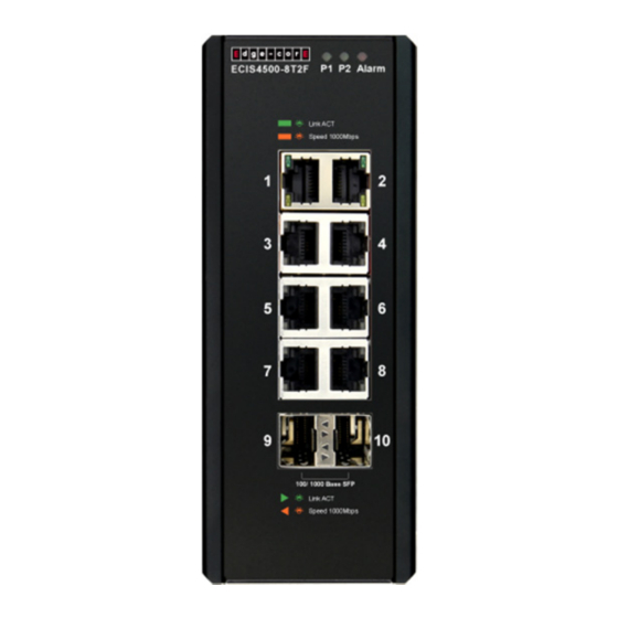
- Page 6 ECIS4500 Quick Installation Guide Faceplate ECIS4500-8T2F ECIS4500-6T4F ECIS4500-6T2F ECIS4500-8P2T4F ECIS4500-8P4F ECIS4500-4P2T2F ECIS4500-4P4F...
-
Page 7: Din Rail Mounting
ECIS4500 Quick Installation Guide DIN-rail mounting Mounting steps: 1. Screw the din-clip with screws in the accessory kit. 2. Hook the unit onto the din-rail. 3. Push the bottom of the unit towards the din-rail until it locks in place. Wall mounting Mounting steps: 1. -
Page 8: Ethernet Interface (Rj-45 Ethernet)
ECIS4500 Quick Installation Guide Ethernet Interface (RJ-45 Ethernet) The switch provides two types of Ethernet interfaces: electrical (RJ-45) and optical (SFP) interfaces. Connecting the Ethernet interface via RJ-45: ● To connect the switch to a PC, use straight-through or cross-over Ethernet cables, ●... -
Page 9: Connecting Power Terminal Block
ECIS4500 Quick Installation Guide Connecting Power Terminal Block The switch can be powered from two power supplies (input range 12V – 58V). Insert the positive and negative wires into V+ and V- contacts on the terminal block respectively and tighten the wire-clamp screws to prevent the wires from being loosened. Note: 1. -
Page 10: Alarm Relay And Ground
ECIS4500 Quick Installation Guide Alarm Relay and Ground The alarm relay output contacts are in the middle of the DC terminal block connector as shown in the figure below. The alarm relay out is “Normal Open”, and it will be closed when detected any predefined failure such as power failures or Ethernet link failures. - Page 11 ECIS4500 Quick Installation Guide To connect the host PC to the console port, a RJ-45 (male) connector-to-RS232 DB9 (female) connector cable is required. The RJ-45 connector of the cable is connected to the CID port of IVS-500; the DB9 connector of the cable is connected to the PC COM port. The pin assignment of the console cable is shown below: Connect and Login to Managed Switch 1.
- Page 12 ECIS4500 Quick Installation Guide CLI Initialization and Configuration (Optional) 1. Connecting to the Ethernet port (RJ-45 Ethernet port) of managed switch 2. Key-in the command under Telnet: telnet 192.168.2.10 3. Login with default account and password. 4. Username: admin; Password: admin Change the IP with commands listed below: CLI Command: enable...
Need help?
Do you have a question about the ECIS4500 Series and is the answer not in the manual?
Questions and answers