
Related Manuals for Nokia IP60


Summary of Contents for Nokia IP60
-
Page 1: User Guide
Nokia IP60 Security Appliance User Guide Part No. N450000643 Rev 001 Published February 2008... - Page 2 IMPORTANT NOTE TO USERS This software and hardware is provided by Nokia Inc. as is and any express or implied warranties, including, but not limited to, implied warranties of merchantability and fitness for a particular purpose are disclaimed. In no event shall Nokia, or its affiliates, subsidiaries or suppliers be liable for any direct, indirect, incidental, special, exemplary, or consequential damages (including, but not limited to, procurement of substitute goods or services;...
- Page 3 Singapore 119968 Nokia Customer Support Web Site: https://support.nokia.com/ Email: tac.support@nokia.com Americas Europe Voice: 1-888-361-5030 or Voice: +44 (0) 125-286-8900 1-613-271-6721 Fax: 1-613-271-8782 Fax: +44 (0) 125-286-5666 Asia-Pacific Voice: +65-67232999 Fax: +65-67232897 050602 Nokia IP60 Security Appliance User Guide...
- Page 4 Nokia IP60 Security Appliance User Guide...
-
Page 5: Table Of Contents
Introduction to Information Security ....................29 The Nokia IP60 Firewall ........................32 Installing and Setting Up the Nokia IP60 Appliance ............... 39 Before You Install the Nokia IP60 Appliance ................... 39 Nokia IP60 and Nokia IP60 Wireless Installation ................50 Cascading Your Appliance ....................... - Page 6 Viewing Wireless Statistics ......................226 Viewing the Routing Table ......................229 Setting Your Security Policy ......................231 The Nokia IP60 Firewall Security Policy..................232 Default Security Policy ........................233 Setting the Firewall Security Level ....................233 Nokia IP60 Security Appliance User Guide...
- Page 7 Automatic and Manual Updates ...................... 340 Working with VPNs .......................... 343 Overview ............................343 Setting Up Your Nokia IP60 Appliance as a VPN Server .............. 347 Adding and Editing VPN Sites ......................359 Viewing and Deleting VPN Sites ....................383 Enabling/Disabling a VPN Site .......................
- Page 8 Configuring SNMP ......................... 432 Setting the Time on the Appliance ....................436 Using Diagnostic Tools ........................439 Backing Up the Nokia IP60 Appliance Configuration ..............451 Resetting the Nokia IP60 Appliance to Defaults ................453 Running Diagnostics ........................455 Rebooting the Nokia IP60 Appliance ....................456 Using Network Printers ........................
- Page 9 Contents Setting Up Network Printers ......................457 Configuring Computers to Use Network Printers ................459 Viewing Network Printers ....................... 470 Changing Network Printer Ports ..................... 471 Resetting Network Printers ......................472 Troubleshooting ..........................473 Connectivity ............................ 473 Service Center and Upgrades ......................475 Other Problems ..........................
-
Page 11: About This Guide
Note: Notes are denoted by indented text and preceded by the Note icon. Warning: Warnings are denoted by indented text and preceded by the Warning icon. Each task is marked with an icon indicating the Nokia IP60 product required to perform the task, as follows: If this icon appears... -
Page 13: Introduction
All IP60 appliances can be integrated into an overall enterprise security policy for maximum security. Check Point's Security Management Architecture (SMART) delivers a single enterprise-wide security policy that you can centrally manage and automatically deploy to an unlimited number of Nokia IP60 gateways. - Page 14 Console Port (Serial) Print Server — USB 2.0 Ports Firewall & Security Features Check Point Stateful Inspection Firewall Application Intelligence SmartDefense™ (IPS) Network Address Translation (NAT) Four Preset Security Policies Anti-spoofing Voice over IP (H.323) Support Nokia IP60 Security Appliance User Guide...
- Page 15 Nokia IP60 Products Unlimited INSPECT Policy Rules Instant Messenger Blocking / Monitoring P2P File Sharing Blocking / Monitoring Port-based and Tag-based 32 (XU) / 10 (Other Models) VLAN Port-based Security (802.1x) Web Rules Secure HotSpot (Guest Access) Remote Access Users...
- Page 16 Backup Internet Connection DHCP Server, Client, and Relay MAC Cloning Network Address Translation (NAT) Rules Static Routes, Source Routes, and Service- Based Routes Ethernet Cable Type Recognition DiffServ Tagging Automatic Gateway Failover (HA) Dynamic Routing Nokia IP60 Security Appliance User Guide...
- Page 17 Desktop, Wall, or Rack Mounting* Warranty 1 Year Hardware * Rack mounting requires the optional rack mounting kit (sold separately). Nokia IP60 Wireless Features Table 2: Nokia IP60 Wireless Series Features Feature Nokia IP60 Wireless Concurrent Users 8 / 16 / 32 / Unrestricted...
- Page 18 Voice over IP (H.323) Support Unlimited INSPECT Policy Rules Instant Messenger Blocking / Monitoring P2P File Sharing Blocking / Monitoring Port-based, Tag-based, and 32 (WU) / 10 (Other Models) Other VLAN Port-based Security (802.1x) Nokia IP60 Security Appliance User Guide...
- Page 19 Nokia IP60 Products Web Rules Secure HotSpot (Guest Access) Remote Access Users 1/10/15/25 VPN Server with OfficeMode and SecuRemote, L2TP RADIUS Support Site-to-Site VPN Gateway Route-based VPN Backup VPN Gateways Remote Access VPN Client SecuRemote (Included) Site-to-Site VPN Tunnels (Managed)
- Page 20 Management Central Management Check Point SmartCenter, Check Point SmartLSM, Check Point SmartUpdate, CheckPoint Provider-1, SofaWare Local Management HTTP / HTTPS / SSH / SNMP / Serial CLI Remote Desktop Integrated Microsoft Terminal Services Client Nokia IP60 Security Appliance User Guide...
-
Page 21: Software Requirements
* Rack mounting requires the optional rack mounting kit (sold separately). Optional Security Services The following subscription security services are available to IP60 owners by connecting to a Service Center: Firewall Security and Software Updates... - Page 22 Nokia IP60 Products Note: For proper operation of the IP60 Portal, disable any pop-up blockers for http://my.firewall. Getting to Know Your Nokia IP60 Appliance Package Contents The Nokia IP60 package includes the following: Nokia IP60 Internet Security Appliance Power supply...
-
Page 23: Network Requirements
A broadband Internet connection via cable or DSL modem with Ethernet interface (RJ-45) Rear Panel All physical connections (network and power) are made via the rear panel of your IP60 appliance. Figure 1: Nokia IP60 Appliance Rear Panel The following table lists the Nokia IP60 appliance's rear panel elements. -
Page 24: Front Panel
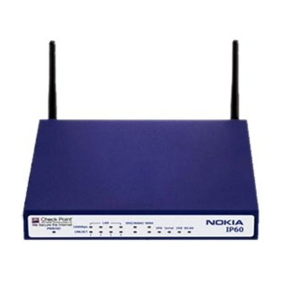
Local Area Network switch: Four Ethernet ports (RJ-45) used for connecting computers or other network devices Front Panel The Nokia IP60 appliance includes several status LEDs that enable you to monitor the appliance’s operation. Figure 2: Nokia IP60 Appliance Front Panel For an explanation of the Nokia IP60 appliance’s status LEDs, see the table below. - Page 25 VPN tunnels established, no activity Serial No Serial port activity Flashing (Green) Serial port activity Getting to Know Your Nokia IP60 Wireless Appliance Package Contents The Nokia IP60 Wireless package includes the following: Nokia IP60 Wireless Internet Security Appliance Power supply...
- Page 26 A broadband Internet connection via cable or DSL modem with Ethernet interface (RJ-45) Rear Panel All physical connections (network and power) are made via the rear panel of your IP60 appliance. Figure 3: Nokia IP60 Wireless Appliance Rear Panel Figure 4: Nokia IP60 Wireless Appliance Rear Panel The following table lists the Nokia IP60 Wireless appliance's rear panel elements.
- Page 27 Antenna connectors, used to connect the supplied wireless antennas . ANT 2 Front Panel The Nokia IP60 Wireless appliance includes several status LEDs that enable you to monitor the appliance’s operation. Figure 5: Nokia IP60 Wireless Appliance Front Panel For an explanation of the Nokia IP60 Wireless appliance’s status LEDs, see the table below.
-
Page 28: Contacting Technical Support
No WLAN activity Flashing (Green) WLAN activity Contacting Technical Support If there is a problem with your IP60 appliance, see http://support.nokia.com. You can also download the latest version of this guide from the Nokia Support site. Nokia IP60 Security Appliance User Guide... -
Page 29: Security
Network security is but a small part of information security, which in turn is only a fraction of general security. In order to understand why the IP60 appliance is the best product for securing the business network, we must first examine information security requirements in general. - Page 30 Confidential papers must be shredded after use. An organization's security policy is usually designed by a person who is in charge of handling all security matters for the organization. This person is called a security manager. Nokia IP60 Security Appliance User Guide...
- Page 31 Introduction to Information Security In order for a security policy be effective, it must be accompanied by the following measures: Awareness - A security policy must be accompanied by steps taken to increase the employees' awareness of security issues. If employees are unaware of a security policy rule and the reason for it, they are likely to break it.
-
Page 32: The Nokia Ip60 Firewall
Information manipulation - The ability to perform logical or arithmetic functions on data in any part of the packet. For example, the ability to encrypt packets. Nokia IP60 Security Appliance User Guide... - Page 33 The Nokia IP60 Firewall Old Firewall Technologies Older firewall technologies, such as packet filtering and application-layer gateways, are still in use in some environments. It is important to familiarize yourself with these technologies, so as to better understand the benefits and advantages of the Check Point Stateful Inspection firewall technology.
- Page 34 The Nokia IP60 firewall also stores and updates the state and context information in dynamic tables, providing cumulative data against which it inspects subsequent communications.
- Page 35 The Nokia IP60 Firewall FTP connections are unique, since they are established using two sessions or channels: one for command (AKA control) and one for data. The following table describes the steps of establishing a Passive FTP connection, where: C is the client port used in the command session, D is the client port used in the data session, and P is the server port used in the data session.
- Page 36 HTTP proxy for HTTP session, and so on), and since the application-layer gateway can only support a certain number of proxies, its usefulness and scalability is limited. Finally, this approach exposes the operating system to external threats. Nokia IP60 Security Appliance User Guide...
- Page 37 The entire stream of data is analyzed for conformity to protocol definition and for packet-payload validity. True Stateful Inspection means tracking the state and context of all communications. This requires a detailed level of application awareness. The IP60 appliance provides true Stateful Inspection. Chapter 2: Security...
-
Page 39: Installing And Setting Up The Nokia Ip60 Appliance
Chapter 3 Installing and Setting Up the Nokia IP60 Appliance This chapter describes how to properly set up and install your Nokia IP60 appliance in your networking environment. This chapter includes the following topics: Before You Install the Nokia IP60 Appliance ..........39 Nokia IP60 and Nokia IP60 Wireless Installation ........ - Page 40 Before You Install the Nokia IP60 Appliance Windows Vista Checking the TCP/IP Installation 1. Click Start > Control Panel. The Control Panel window appears. 2. Under Network and Internet, click View network status and tasks. The Network Sharing Center screen appears.
- Page 41 Before You Install the Nokia IP60 Appliance The Network Connections screen appears. 4. Double-click the Local Area Connection icon. The Local Area Connection Status window opens. 5. Click Properties. Chapter 3: Installing and Setting Up the Nokia IP60 Appliance...
- Page 42 Before You Install the Nokia IP60 Appliance The Local Area Connection Properties window opens. 6. Check if Internet Protocol Version 4 (TCP/IPv4) appears in the list box and if it is properly configured with the Ethernet card installed on your computer.
- Page 43 Before You Install the Nokia IP60 Appliance 4. Click OK to save the new settings. Your computer is now ready to access your IP60 appliance. Windows 2000/XP Checking the TCP/IP Installation 1. Click Start > Settings > Control Panel. The Control Panel window appears.
- Page 44 Before You Install the Nokia IP60 Appliance The Local Area Connection Properties window appears. 4. In the above window, check if TCP/IP appears in the components list and if it is properly configured with the Ethernet card installed on your computer. If TCP/IP does not appear in the Components list, you must install it as described in the next section.
- Page 45 3. Choose Internet Protocol (TCP/IP) and click OK. TCP/IP protocol is installed on your computer. TCP/IP Settings 1. In the Local Area Connection Properties window, double-click the Internet Protocol (TCP/IP) component, or select it and click Properties. Chapter 3: Installing and Setting Up the Nokia IP60 Appliance...
- Page 46 (Note that 192.168.10 is the default value, and it may vary if you changed it in the Network > My Network page.) 3. Click the Obtain DNS server address automatically radio button. 4. Click OK to save the new settings. Your computer is now ready to access your IP60 appliance. Nokia IP60 Security Appliance User Guide...
- Page 47 The TCP/IP window appears. 2. Click the Connect via drop-down list, and select Ethernet. 3. Click the Configure drop-down list, and select Using DHCP Server. 4. Close the window and save the setup. Chapter 3: Installing and Setting Up the Nokia IP60 Appliance...
- Page 48 Before You Install the Nokia IP60 Appliance Mac OS-X Use the following procedure for setting up the TCP/IP Protocol. 1. Choose Apple -> System Preferences. The System Preferences window appears. 2. Click Network. The Network window appears. Nokia IP60 Security Appliance User Guide...
- Page 49 Before You Install the Nokia IP60 Appliance 3. Click Configure. TCP/IP configuration fields appear. 4. Click the Configure IPv4 drop-down list, and select Using DHCP. 5. Click Apply Now. Chapter 3: Installing and Setting Up the Nokia IP60 Appliance...
-
Page 50: Nokia Ip60 And Nokia Ip60 Wireless Installation
4. Connect the power supply to the appliance's power socket, labeled PWR. 5. Plug the power supply into the wall electrical outlet. Warning: The IP60 appliance power supply is compatible with either 100, 120 or 230 VAC input power. Verify that the wall outlet voltage is compatible with the voltage specified on your power supply. - Page 51 Preparing the IP60 Appliance for a Wireless Connection To prepare the Nokia IP60 Wireless appliance for a wireless connection 1. Connect the antennas that came with your Nokia IP60 Wireless appliance to the ANT1 and ANT2 antenna connectors in the appliance's rear panel.
- Page 52 Your Nokia IP60 Edge appliance is wall mounted. You can now connect it to your computer. Securing the IP60 Appliance against Theft The Nokia IP60 Edge appliance features a security slot to the rear of the right panel, which enables you to secure your appliance against theft, using an anti-theft security device.
- Page 53 The bolt has two states, Open and Closed, and is used to connect the looped security cable to the appliance's security slot. To install an anti-theft device on the Nokia IP60 Edge appliance 1. If your anti-theft device has a combination lock, set the desired code, as described in the documentation that came with your device.
-
Page 54: Cascading Your Appliance
Cascading Your Appliance 4. Insert the bolt into the Nokia IP60 Edge appliance's security slot, then slide the bolt to the Closed position until the bolts holes are aligned. 5. Thread the anti-theft device's pin through the bolt’s holes, and insert the pin into the main body of the anti-theft device, as described in the documentation that came with your device. -
Page 55: Connecting The Appliance To Network Printers
For information on setting up network printers, see Setting up Network Printers on page 457. Setting Up the IP60 Appliance After you have installed the IP60 appliance, you must set it up using the steps shown below. When setting up your IP60 appliance for the first time after installation, these steps follow each other automatically. - Page 56 Setting Up the IP60 Appliance Logging on to the IP60 Portal and setting up your password Initial Login to the Nokia IP60 Portal on page 59 Configuring an Internet connection Using the Internet Wizard on page 68 Setting the Time on your IP60 appliance...
- Page 57 Setting Up the IP60 Appliance The Firmware page appears. 2. Click Nokia IP60 Setup Wizard. The Nokia IP60 Setup Wizard opens with the Welcome page displayed. Chapter 3: Installing and Setting Up the Nokia IP60 Appliance...
-
Page 59: Getting Started
Initial Login to the Nokia IP60 Portal Chapter 4 Getting Started This chapter contains all the information you need in order to get started using your IP60 appliance. This chapter includes the following topics: Initial Login to the Nokia IP60 Portal ............59 Logging on to the Nokia IP60 Portal ............ -
Page 60: Logging On To The Nokia Ip60 Portal
Internet Wizard on page 68. After you have completed the Internet Wizard, the Setup Wizard continues to guide you through appliance setup. For more information, see Setting Up the Nokia IP60 Appliance on page 55. Internet Setup Internet Setup offers advanced setup options, such as configuring two Internet connections. To use Internet Setup, click Cancel and refer to Using Internet Setup on page 76. -
Page 61: Accessing The Nokia Ip60 Portal Remotely Using Https
Accessing the Nokia IP60 Portal Remotely Using HTTPS You can access the Nokia IP60 Portal remotely (from the Internet) through HTTPS. HTTPS is a protocol for accessing a secure Web server. It is used to transfer confidential user information. If desired, you can also use HTTPS to access the Nokia IP60 Portal from your internal network. - Page 62 The following things happen in the order below: If this is your first attempt to access the Nokia IP60 Portal through HTTPS, the certificate in the IP60 appliance is not yet known to the browser, so the Security Alert dialog box appears.
-
Page 63: Using The Nokia Ip60 Portal
Using the Nokia IP60 Portal Using the Nokia IP60 Portal The Nokia IP60 Portal is a Web-based management interface, which enables you to manage and configure the IP60 appliance operation and options. The Nokia IP60 Portal consists of three major elements. -
Page 64: Main Menu
Allows you to manage and configure your network settings and Internet connections. Setup Provides a set of tools for managing your IP60 appliance. Allows you to upgrade your license and firmware and to configure HTTPS access to your IP60 appliance. -
Page 65: Logging Off
Connected. You are connected to the Service Center, and security services are active. Logging off Logging off terminates your administration session. Any subsequent attempt to connect to the Nokia IP60 Portal will require re-entering of the administration password. Chapter 4: Getting Started... - Page 66 Logging off To log off of the Nokia IP60 Portal Do one of the following: If you are connected through HTTP, click Logout in the main menu. The Login page appears. If you are connected through HTTPS, the Logout option does not appear in the main menu.
-
Page 67: Configuring The Internet Connection
Configuring a Backup Internet Connection ..........105 Configuring WAN Load Balancing ............106 Overview In order to access the Internet through your IP60 appliance, you must configure one of the following connection types: Ethernet-based connection You can configure an Ethernet-based connection in all models. An Ethernet-based connection can be connected to another network by means of a switch, a router, a bridge, or an Ethernet-enabled broadband modem. -
Page 68: Using The Internet Wizard
Using the Internet Wizard Using the Internet Wizard The Internet Wizard allows you to configure your IP60 appliance for Internet connection quickly and easily through its user-friendly interface. Note: The first time you log on to the Nokia IP60 Portal, the Internet Wizard starts automatically as part of the Setup Wizard. - Page 69 Using the Internet Wizard Configuring an Ethernet-Based Connection on Non-ADSL Models To configure an Ethernet-Based connection 1. Click Network in the main menu, and click the Internet tab. The Internet page appears. 2. Click Internet Wizard. The Internet Wizard opens with the Welcome page displayed. 3.
- Page 70 If you chose Cable Modem, continue at Using a Cable Modem Connection on page 74. If you chose Static IP, continue at Using a Static IP Connection on page 74. If you chose DHCP, continue at Using a DHCP Connection on page 75. Nokia IP60 Security Appliance User Guide...
- Page 71 Using the Internet Wizard Using a PPPoE Connection If you selected the PPPoE (PPP over Ethernet) connection method, the PPP Configuration dialog box appears. 1. Complete the fields using the information in the following table. 2. Click Next. The Confirmation screen appears. 3.
- Page 72 Table 14: PPPoE Connection Fields In this field… Do this… Username Type your user name. Password Type your password. Confirm password Type your password again. Service Type your service name. This field can be left blank. Nokia IP60 Security Appliance User Guide...
- Page 73 Using the Internet Wizard Using a PPTP Connection If you selected the PPTP connection method, the PPP Configuration dialog box appears. 1. Complete the fields using the information in the following table. 2. Click Next. The Confirmation screen appears. 3. Click Next. The system attempts to connect to the Internet via the specified connection.
- Page 74 The Confirmation screen appears. 3. Click Next. The system attempts to connect to the Internet via the specified connection. The Connecting… screen appears. At the end of the connection process the Connected screen appears. 4. Click Finish. Nokia IP60 Security Appliance User Guide...
- Page 75 Table 16: PPPoE Connection Fields In this field… Do this… IP Address Type the static IP address of your IP60 appliance. Subnet Mask Select the subnet mask that applies to the static IP address of your IP60 appliance. Type the IP address of your ISP’s default gateway.
-
Page 76: Using Internet Setup
168. To configure the Internet connection using Internet Setup 1. Click Network in the main menu, and click the Internet tab. The Internet page appears. 2. Next to the desired Internet connection, click Edit. Nokia IP60 Security Appliance User Guide... - Page 77 Using Internet Setup The Internet Setup page appears. 3. Do one of the following: To configure an ADSL connection using the internal ADSL modem, continue at Configuring a Direct ADSL Connection on page Error! Bookmark not defined.. This option is available in ADSL models only. To configure an Ethernet-based connection, continue at Configuring an Ethernet-Based Connection on page 77.
- Page 78 For information on configuring bridged connections, see Adding Internet Connections to Bridges on page 168. Using a LAN Connection 1. Complete the fields using the relevant information in Internet Setup Fields on page 89. Nokia IP60 Security Appliance User Guide...
- Page 79 New fields appear, depending on the check boxes you selected. 2. Click Apply. The IP60 appliance attempts to connect to the Internet, and the Status Bar displays the Internet status ―Connecting‖. This may take several seconds. Once the connection is made, the Status Bar displays the Internet status ―Connected‖.
- Page 80 New fields appear, depending on the check boxes you selected. 2. Click Apply. The IP60 appliance attempts to connect to the Internet, and the Status Bar displays the Internet status ―Connecting‖. This may take several seconds. Once the connection is made, the Status Bar displays the Internet status ―Connected‖.
- Page 81 Using Internet Setup Using a PPPoE Connection 1. Complete the fields using the relevant information in Internet Setup Fields on page 89. Chapter 5: Configuring the Internet Connection...
- Page 82 New fields appear, depending on the check boxes you selected. 2. Click Apply. The IP60 appliance attempts to connect to the Internet, and the Status Bar displays the Internet status ―Connecting‖. This may take several seconds. Once the connection is made, the Status Bar displays the Internet status ―Connected‖.
- Page 83 Using Internet Setup Using a PPTP Connection 1. Complete the fields using the relevant information in Internet Setup Fields on page 89. Chapter 5: Configuring the Internet Connection...
- Page 84 New fields appear, depending on the check boxes you selected. 2. Click Apply. The IP60 appliance attempts to connect to the Internet, and the Status Bar displays the Internet status ―Connecting‖. This may take several seconds. Once the connection is made, the Status Bar displays the Internet status ―Connected‖.
- Page 85 Using Internet Setup Using a Telstra (BPA) Connection Use this Internet connection type only if you are subscribed to Telstra® BigPond™ Internet. Telstra BigPond is a trademark of Telstra Corporation Limited. 1. Complete the fields using the relevant information in Internet Setup Fields on page 89. Chapter 5: Configuring the Internet Connection...
- Page 86 New fields appear, depending on the check boxes you selected. 2. Click Apply. The IP60 appliance attempts to connect to the Internet, and the Status Bar displays the Internet status ―Connecting‖. This may take several seconds. Once the connection is made, the Status Bar displays the Internet status ―Connected‖.
- Page 87 Using Internet Setup The Connection Type field displays Dialup. 2. Complete the fields using the relevant information in Internet Setup Fields on page 89. Chapter 5: Configuring the Internet Connection...
- Page 88 New fields appear, depending on the check boxes you selected. 3. Click Apply. The IP60 appliance attempts to connect to the Internet, and the Status Bar displays the Internet status ―Connecting‖. This may take several seconds. Once the connection is made, the Status Bar displays the Internet status ―Connected‖.
- Page 89 Using Internet Setup Table 17: Internet Setup Fields In this field… Do this… ADSL Link Settings DSL Standard Select the standard to support for the DSL line, as specified by your ISP. VPI Number Type the VPI number to use for the ATM virtual path, as specified by your ISP.
- Page 90 The default value is 0. Obtain IP address Clear this option if you do not want the IP60 appliance to obtain an IP automatically address automatically using DHCP. (using DHCP) IP Address Type the static IP address of your IP60 appliance.
- Page 91 Using Internet Setup In this field… Do this… Name Servers Obtain Domain Clear this option if you want the IP60 appliance to obtain an IP address Name Servers automatically using DHCP, but not to automatically configure DNS automatically servers. Obtain WINS...
- Page 92 DMZ/WAN2 port must be configured as WAN2; otherwise this field is disabled. For information on configuring ports, see Managing Ports on page 148. Hardware MAC This field displays the IP60 appliance's MAC address. Address This field is read-only. Cloned MAC...
- Page 93 Using Internet Setup In this field… Do this… Load Balancing Load Balancing If you are using WAN load balancing, type a value indicating the amount Weight of traffic that should be routed though this connection relative to the other connection. For example, if you assign the primary connection a weight of 100, and you assign the secondary connection a weight of 50, twice as much traffic will be routed through the primary connection as through the secondary...
- Page 94 If it is determined that the Internet connection is down, and two Internet connections are defined, a failover will be performed to the second Internet connection, ensuring continuous Internet connectivity. This option is selected by default. Nokia IP60 Security Appliance User Guide...
- Page 95 Using Internet Setup In this field… Do this… While the Probe Next Hop option checks the availability of the next hop Connection Probing Method router, which is usually at your ISP, connectivity to the next hop router does not always indicate that the Internet is accessible. For example, if there is a problem with a different router at the ISP, the next hop will be reachable, but the Internet might be inaccessible.
-
Page 96: Setting Up Dialup Modems
See Setting Up a USB Modem on page 100. Setting Up an RS232 Modem Note: Your RS232 dialup modem and your IP60 appliance's Serial port must be configured for the same speed. By default, the appliance's Serial port's speed is 57600 bps. For information on changing the Serial port's speed, refer to the Nokia IP60 CLI Reference Guide. - Page 97 Setting Up Dialup Modems The Ports page appears. 3. Next to Serial, click Edit. The Port Setup page appears. 4. In the Assign to Network drop-down list, select Dialup. Chapter 5: Configuring the Internet Connection...
- Page 98 Select the dial mode the modem uses. Port Speed Select the Serial port's speed (in bits per second). The Serial port's speed must match that of the attached dialup modem. The default value is 57600. Nokia IP60 Security Appliance User Guide...
- Page 99 Setting Up Dialup Modems In this field… Do this… Answer incoming Select this option to specify that the modem should answer incoming PPP calls PPP calls. This allows accessing the appliance out of band for maintenance purposes, in case the primary Internet connection fails. Chapter 5: Configuring the Internet Connection...
- Page 100 To set up a USB modem 1. Connect a USB-based modem to one of your IP60 appliance's USB ports. For information on locating the USB ports, see Introduction on page 13. 2. Click Network in the main menu, and click the Ports tab.
- Page 101 Setting Up Dialup Modems The USB Devices page appears. If the IP60 appliance detected the modem, the modem is listed on the page. If the modem is not listed, check that you connected the modem correctly, then click Refresh to refresh the page.
-
Page 102: Viewing Internet Connection Information
Viewing Internet Connection Information You can view information on your Internet connection(s) in terms of status, duration, and activity. To view Internet connection information 1. Click Network in the main menu, and click the Internet tab. Nokia IP60 Security Appliance User Guide... - Page 103 Viewing Internet Connection Information The Internet page appears. For an explanation of the fields on this page, see the following table. 2. To view activity information for a connection, mouse-over the information icon next to the desired connection. A tooltip displays the number of bytes sent and received bytes through the connection. 3.
- Page 104 Indicates the connection duration, if active. The duration is given in the format hh:mm:ss, where: hh=hours mm=minutes ss=seconds IP Address Your IP address. Enabled Indicates whether or not the connection is enabled. For further information, see Enabling/Disabling the Internet Connection on page 105 Nokia IP60 Security Appliance User Guide...
-
Page 105: Enabling/Disabling The Internet Connection
The Internet connection retains its Connected/Not Connected status until the IP60 appliance is rebooted. The IP60 appliance then connects to the Internet if the connection is enabled. For information on enabling an Internet connection, see Enabling/Disabling the Internet Connection on page 105. -
Page 106: Configuring Wan Load Balancing
To prevent disruption of stateful protocols, the IP60 appliance will route all traffic between this pair to the specified Internet connection, so long as the pair remains in the load balancing table. - Page 107 Configuring WAN Load Balancing Note: To ensure continuous Internet connectivity, if one of the Internet connections fails, all traffic will be routed to the other connection. To configure WAN load balancing 1. Configure the desired load balancing weight for both the primary and secondary Internet connections.
-
Page 109: Managing Your Network
Web portal, you can connect to the appliance through the serial console and correct the error (see Using a Console on page 427). Alternatively, you can reset the IP60 appliance to its default settings (see Resetting the IP60 appliance to Defaults on page 453). - Page 110 Configuring the LAN Network To configure the LAN network 1. Click Network in the main menu, and click the My Network tab. The My Network page appears. 2. Click Edit in the LAN network’s row. Nokia IP60 Security Appliance User Guide...
- Page 111 8. Click OK. A success message appears. Changing IP Addresses If desired, you can change your IP60 appliance’s internal IP address, or the entire range of IP addresses in your internal network. To change IP addresses 1. Click Network in the main menu, and click the My Network tab.
- Page 112 Configuring Network Settings The Edit Network Settings page appears. 3. To change the IP60 appliance’s internal IP address, enter the new IP address in the IP Address field. 4. To change the internal network range, enter a new value in the Subnet Mask field.
- Page 113 If you want to use a DHCP server on the Internet or via a VPN, instead of the Nokia IP60 DHCP server, you can configure DHCP relay. When in DHCP relay mode, the IP60 appliance relays information from the desired DHCP server to the devices on your network.
- Page 114 6. If your computer is configured to obtain its IP address automatically (using DHCP), and either the Nokia IP60 DHCP server or another DHCP server is enabled, restart your computer. If you enabled the DHCP server, your computer obtains an IP address in the DHCP address range.
- Page 115 Configuring the DHCP Address Range By default, the Nokia IP60 DHCP server automatically sets the DHCP address range. The DHCP address range is the range of IP addresses that the DHCP server can assign to network devices. IP addresses outside of the DHCP address range are reserved for statically addressed computers.
- Page 116 6. If your computer is configured to obtain its IP address automatically (using DHCP), and either the Nokia IP60 DHCP server or another DHCP server is enabled, restart your computer. Your computer obtains an IP address in the new DHCP address range.
- Page 117 7. Click OK. A success message appears 8. If your computer is configured to obtain its IP address automatically (using DHCP), and either the Nokia IP60 DHCP server or another DHCP server is enabled, restart your computer. Chapter 6: Managing Your Network...
- Page 118 1. Click Network in the main menu, and click the My Network tab. The My Network page appears. 2. In the desired network's row, click Edit. The Edit Network Settings page appears. 3. In the DHCP area, click Options. Nokia IP60 Security Appliance User Guide...
- Page 119 Configuring Network Settings The DHCP Server Options page appears. 4. Complete the fields using the relevant information in the following table. Chapter 6: Managing Your Network...
- Page 120 For example, if the domain suffix is set to "mydomain.com", and the client tries to resolve the name ―mail‖, the suffix will be automatically appended to the name, resulting in ―mail.mydomain.com‖. Nokia IP60 Security Appliance User Guide...
- Page 121 Configuring Network Settings In this field… Do this… Name Servers Automatically assign Clear this option if you do not want the gateway to act as a DNS relay DNS server server and pass its own IP address to DHCP clients. (recommended) Normally, it is recommended to leave this option selected.
- Page 122 If you have more than one computer in the DMZ network, connect a hub or switch to the DMZ port, and connect the DMZ computers to the hub. 2. Click Network in the main menu, and click the Ports tab. Nokia IP60 Security Appliance User Guide...
- Page 123 Configuring Network Settings The Ports page appears. 3. Next to the DMZ/WAN2 port, click Edit. The Port Setup page appears. 4. In the Assign to network drop-down list, select DMZ. 5. Click Apply. A warning message appears. 6. Click OK. 7.
- Page 124 VPN Clients on the same network will be unable to communicate with each other via the Nokia IP60 Internal VPN Server. This is because their IP addresses are on the same subnet, and they therefore attempt to communicate directly over the local network, instead of through the secure VPN link.
- Page 125 Configuring Network Settings The My Network page appears. 2. In the OfficeMode network's row, click Edit. The Edit Network Settings page appears. 3. In the Mode drop-down list, select Enabled. The fields are enabled. 4. In the IP Address field, type the IP address to use as the OfficeMode network's default gateway. Note: The OfficeMode network must not overlap other networks.
- Page 126 Your IP60 appliance allows you to partition your network into several virtual LAN networks (VLANs). A VLAN is a logical network behind the IP60 appliance. Computers in the same VLAN behave as if they were on the same physical network: traffic flows freely between them, without passing through a firewall.
- Page 127 Configuring Network Settings The IP60 appliance supports the following VLAN types: Tag-based In tag-based VLAN you use one of the gateway’s ports as a 802.1Q VLAN trunk, connecting the appliance to a VLAN-aware switch. Each VLAN behind the trunk is assigned an identifying number called a ―VLAN ID‖, also referred to as a "VLAN tag".
- Page 128 Figure 12: Port-Based VLAN Virtual access point (VAP) In wireless Nokia IP60 models, you can partition the primary WLAN network into wireless VLANs called virtual access points (VAPs). You can use VAPs to grant different permissions to groups of wireless users, by configuring each VAP with the desired security policy and network settings, and then assigning each group of wireless users to the relevant VAP.
- Page 129 Configuring Network Settings Wireless Distribution System (WDS) links In wireless Nokia IP60 models, you can extend the primary WLAN's coverage area, by creating a Wireless Distribution System (WDS). A WDS is a system of access points that communicate with each other wirelessly, without any need for a wired backbone.
- Page 130 7. In the Subnet Mask field, type the VLAN's internal network range. 8. If desired, enable or disable Hide NAT. See Enabling/Disabling Hide NAT on page 112. 9. If desired, configure a DHCP server. Nokia IP60 Security Appliance User Guide...
- Page 131 Configuring Network Settings See Configuring a DHCP Server on page 113. 10. Click Apply. A warning message appears. 11. Click OK. A success message appears. 12. Click Network in the main menu, and click the Ports tab. The Ports page appears. 13.
- Page 132 16. Configure a VLAN trunk (802.1Q) port on the VLAN-aware switch, according to the vendor instructions. Define the same VLAN IDs on the switch. 17. Connect the IP60 appliance's DMZ/WAN2 port to the VLAN-aware switch's VLAN trunk port. Nokia IP60 Security Appliance User Guide...
- Page 133 Configuring Network Settings Deleting VLANs To delete a VLAN 1. If the VLAN is port-based, do the following: Click Network in the main menu, and click the Ports tab. The Ports page appears. Remove all port assignments to the VLAN, by selecting other networks in the drop-down lists.
-
Page 134: Using Network Objects
Normally, the Nokia IP60 DHCP server consistently assigns the same IP address to a specific computer. However, if the Nokia IP60 DHCP server runs out of IP addresses and the computer is down, then the DHCP server may reassign the IP address to a different computer. - Page 135 Using Network Objects Adding and Editing Network Objects You can add or edit network objects via: The Network Objects page This page enables you to add both individual computers and networks. The My Computers page This page enables you to add only individual computers as network objects. The computer's details are filled in automatically in the wizard.
- Page 136 Using Network Objects The Nokia IP60 Network Object Wizard opens, with the Step 1: Network Object Type dialog box displayed. 3. Do one of the following: To specify that the network object should represent a single computer or device, click Single Computer.
- Page 137 Using Network Objects If you chose Network, the dialog box does not include this option. 5. Complete the fields using the information in the tables below. 6. Click Next. The Step 3: Save dialog box appears. 7. Type a name for the network object in the field. 8.
- Page 138 To add a network object, click Add next to the desired computer. To edit a network object, click Edit next to the desired computer. The Nokia IP60 Network Object Wizard opens, with the Step 1: Network Object Type dialog box displayed.
- Page 139 Using Network Objects 8. Click Finish. The new object appears in the Network Objects page. Chapter 6: Managing Your Network...
- Page 140 My HotSpot page. Furthermore, users on HotSpot networks will be able to access this computer without viewing the My HotSpot page. Exclude this computer Select this option to exclude this computer from the Web Filtering from Web Filtering service and Web rule enforcement. Nokia IP60 Security Appliance User Guide...
- Page 141 Using Network Objects Table 24: Network Object Fields for a Network In this field… Do this… IP Range Type the range of local computer IP addresses in the network. Perform Static NAT Select this option to map the network's IP address range to a range of (Network Address Internet IP addresses of the same size.
-
Page 142: Configuring Network Service Objects
The Network Services page appears with a list of network service objects. 2. Do one of the following: To add a network service object, click New. To edit an existing network service object, click Edit next to the desired object in the list. Nokia IP60 Security Appliance User Guide... - Page 143 Configuring Network Service Objects The Nokia IP60 Network Service Wizard opens, with the Step 1: Network Service Details dialog box displayed. 3. Complete the fields using the information in the table below. 4. Click Next. The Step 2: Network Service Name dialog box appears.
-
Page 144: Using Static Routes
ISP's default gateway IP address is dynamically assigned to the gateway, as this approach allows you to route traffic to the Internet connection by specifying its name, instead of a static IP address. Nokia IP60 Security Appliance User Guide... - Page 145 Using Static Routes Note: If the static route's next hop is an Internet connection that is currently unavailable, the IP60 appliance sends matching traffic through the static route with the next-lowest metric. Packets with a source, destination, or network service that do not match any defined static route are routed to the default gateway.
- Page 146 4. Click Next. The Step 2: Next Hop and Metric dialog box appears. 5. Complete the fields using the relevant information in the following table. 6. Click Next. The new static route is saved. Nokia IP60 Security Appliance User Guide...
- Page 147 Using Static Routes Table 26: Static Route Fields In this field… Do this… Source Specify the source network (source routing). This can be either of the following: ANY. This route applies to packets originating in any network. Specified Network. This route applies to packet originating in a specific network.
-
Page 148: Managing Ports
Click OK. The route is deleted. Managing Ports The IP60 appliance enables you to quickly and easily assign its ports to different uses, as shown in the following table. If desired, you can also disable ports. Table 27: Ports and Assignments You can assign this port... - Page 149 Serial console Printers USB-based modems The IP60 appliance also allows you to restrict each port to a specific link speed and duplex setting and to configure its security scheme. For information on port-based security, see Using Port-Based Security on page 247.
- Page 150 Managing Ports The Ports page appears. In non-ADSL models, this page appears as follows: The page displays the information for each port, as described in the following table. 2. To refresh the display, click Refresh. Nokia IP60 Security Appliance User Guide...
- Page 151 Managing Ports Table 28: Ports Fields This field… Displays… Assign To The port's current assignment. For example, if the DMZ/WAN2 port is currently used for the DMZ, the field displays "DMZ". Status The port's current status. This can be any of the following: The detected link speed and duplex (Full Duplex or Half Duplex) No Link.
- Page 152 Setting Up a USB Modem on page 100 To modify a port assignment 1. Click Network in the main menu, and click the Ports tab. The Ports page appears. 2. Next to the desired port, click Edit. Nokia IP60 Security Appliance User Guide...
- Page 153 The port is reassigned to the specified network or purpose. Modifying Link Configurations By default, the IP60 appliance automatically detects the link speed and duplex. If desired, you can manually restrict the appliance's ports to a specific link speed and duplex setting.
- Page 154 Select Automatic Detection to configure the port to automatically detect the link speed and duplex. This is the default. 4. Click Apply. A warning message appears. 5. Click OK. The port uses the specified link speed and duplex. Nokia IP60 Security Appliance User Guide...
- Page 155 Managing Ports Resetting Ports to Defaults You can reset the IP60 appliance's ports to their default link configurations ("Automatic Detection") and default assignments (shown in the following table). Table 30: Default Port Assignments Port Default Assignment LAN 1-8 DMZ / WAN2 This port is always assigned to the WAN.
- Page 156 2. Next to the desired port, click Edit. The Port Setup page appears. 3. Click Default. A confirmation message appears. 4. Click OK. The port is reset to its default assignment and to "Automatic Detection" link configuration. Nokia IP60 Security Appliance User Guide...
-
Page 157: Using Bridges
Adding Internet Connections to Bridges ..........168 Deleting Bridges ..................172 Overview The IP60 appliance enables you to connect multiple network segments at the data-link layer, by configuring a bridge. Bridges offer the following advantages: Easy network segmentation Bridges can be used to compartmentalize an existing network into several security zones, without changing the IP addressing scheme or the routers' configuration. - Page 158 The network interfaces operate as if they were connected by a hub or switch. Figure 13: Bridge with Four VLANs Nokia IP60 Security Appliance User Guide...
- Page 159 Overview For example, if you assign the LAN and primary WLAN networks to a bridge and disable the bridge's internal firewall, the two networks will act as a single, seamless network, and only traffic from the LAN and primary WLAN networks to other networks (for example, the Internet) will be inspected by the firewall.
- Page 160 The IP60 appliance allows you to configure anti-spoofing for bridged network segments. When anti- spoofing is configured for a segment, only IP addresses within a specific IP address range can be sent from that network segment.
- Page 161 Overview 1. The destination MAC address is looked up in the bridge's forwarding table. 2. If the destination MAC address is found in the forwarding table, the packet is forwarded to the corresponding port. 3. If the destination MAC address is not found in the forwarding table, the packet is flooded to all the ports on the bridge.
-
Page 162: Workflow
VStream Antivirus rules, see Adding and Editing Vstream Antivirus Rules on page 313. Adding and Editing Bridges To add or edit a bridge 1. Click Network in the main menu, and click the My Network tab. Nokia IP60 Security Appliance User Guide... - Page 163 Adding and Editing Bridges The My Network page appears. 2. Do one of the following: To add a bridge, click Add Bridge. To edit a bridge, click Edit in the desired bridge's row. The Bridge Configuration page appears. 3. Complete the fields using the following table. 4.
- Page 164 Note: If you select the same priority for all bridges, the root bridge will be elected based on MAC address. The default value is 32768. This field only appears if STP is enabled. Nokia IP60 Security Appliance User Guide...
-
Page 165: Adding Internal Networks To Bridges
Adding Internal Networks to Bridges In this field… Do this… IP Address Type the IP address to use for this gateway on this bridge. Note: The bridge must not overlap other networks. Subnet Mask Select this bridge's subnet mask. Adding Internal Networks to Bridges Note: In order to add a VLAN of any type (port-based, tag-based, VAP, or WDS link) to the bridge, you must first create the desired VLAN. - Page 166 If the assigned bridge uses STP, additional fields appear. 5. Click Apply. A warning message appears. 6. Click OK. A success message appears. In the My Network page, the internal network appears indented under the bridge. Nokia IP60 Security Appliance User Guide...
- Page 167 Type the range of IP addresses that should be allowed on this network. Note: When assigning IP addresses to machines in a bridged network segment, the Nokia IP60 DHCP server allocates only addresses within the allowed IP address range. To enable clients to move between bridged networks without...
-
Page 168: Adding Internet Connections To Bridges
4. Do one of the following: To configure a Bridged PPPoA connection, in the Connection Type field, select PPPoA. This option is available in ADSL models only. Otherwise, in the Connection Type field, select Bridged. Nokia IP60 Security Appliance User Guide... - Page 169 Adding Internet Connections to Bridges New fields appear. 5. Complete the fields specified in the table below. 6. Complete the rest of the fields using the relevant information in Internet Setup Fields on page Chapter 7: Using Bridges...
- Page 170 New fields appear, depending on the selected options, and whether the selected bridge uses STP. 7. Click Apply. The IP60 appliance attempts to connect to the Internet, and the Status Bar displays the Internet status ―Connecting‖. This may take several seconds.
- Page 171 Adding Internet Connections to Bridges Table 33: Bridged Connection Fields In this field… Do this… Bridge Mode Select this option to configure a Bridged PPPoA connection. The Bridge To field appears. This field is relevant for Bridged PPPoA connections only. Bridge To Select the bridge to which you want to add the PPPoA connection.
-
Page 172: Deleting Bridges
3. Click Network in the main menu, and click the My Network tab. The My Network page appears. 4. In the desired bridge’s row, click the Erase icon. A confirmation message appears. 5. Click OK. The bridge is deleted. Nokia IP60 Security Appliance User Guide... -
Page 173: Configuring High Availability
Sample Implementation on Two Gateways ..........178 Overview You can create a High Availability (HA) cluster consisting of two or more IP60 appliances. For example, you can install two IP60 appliances on your network, one acting as the ―Master‖, the default gateway through which all network traffic is routed, and one acting as the ―Backup‖. - Page 174 Overview Note: You can force a fail-over to a passive IP60 appliance. You may want to do this in order to verify that HA is working properly, or if the active IP60 appliance needs repairs. To force a fail-over, switch off the primary box or disconnect it from the LAN network.
-
Page 175: Configuring High Availability On A Gateway
Configuring High Availability on a Gateway The following procedure explains how to configure HA on a single gateway. You must perform this procedure on each IP60 appliance that you want to include in the HA cluster. To configure HA on a IP60 appliance 1. - Page 176 Otherwise, multiple appliances may become active, causing unpredictable problems. The synchronization interface cannot be an Internet connection or a wireless interface. 7. Complete the fields using the information the following table. 8. Click Apply. Nokia IP60 Security Appliance User Guide...
- Page 177 Configuring High Availability on a Gateway A success message appears. 9. If desired, configure WAN HA for both the primary and secondary Internet connection. This setting should be the same for all gateways. For further information, see the Do not connect if this gateway is in passive state field in Using Internet Setup on page 76.
-
Page 178: Sample Implementation On Two Gateways
The default value is 55. If only one HA cluster exists, there is no need to change this value. Sample Implementation on Two Gateways The following procedure illustrates how to configure HA for the following two Nokia IP60 gateways, Gateway A and Gateway B: Table 35: Gateway Details... - Page 179 Sample Implementation on Two Gateways The procedure below shows how to configure HA for both the LAN and DMZ networks. The synchronization interface is the DMZ network, the LAN virtual IP address is 192.168.100.3, and the DMZ virtual IP address is 192.168.101.3. Gateway A is the Active Gateway. To configure HA for Gateway A and Gateway B 1.
- Page 180 If both of Gateway A's Internet connections are down, it deducts from its priority 20 (for the primary connection) and 30 (for the secondary connection), reducing its priority to 50. In this case, Gateway B's priority is the higher priority, and it becomes the Active Gateway. Nokia IP60 Security Appliance User Guide...
-
Page 181: Using Traffic Shaper
Overview Chapter 9 Using Traffic Shaper This chapter describes how to use Traffic Shaper to control the flow of communication to and from your network. This chapter includes the following topics: Overview ....................181 Setting Up Traffic Shaper ................. 182 Predefined QoS Classes ................ -
Page 182: Setting Up Traffic Shaper
"Default" class. Predefined QoS Classes Traffic Shaper provides the following predefined QoS classes. To assign traffic to these classes, define firewall rules as described in Using Rules on page 238. Nokia IP60 Security Appliance User Guide... - Page 183 Predefined QoS Classes Table 36: Predefined QoS Classes Class Weight Delay Sensitivity Useful for Default Medium Normal traffic. (Normal Traffic) All traffic is assigned to this class by default. Urgent High Traffic that is highly sensitive to delay. For (Interactive Traffic) example, IP telephony, videoconferencing, and interactive protocols that require quick user response, such as telnet.
-
Page 184: Adding And Editing Classes
The Quality of Service Classes page appears. 2. Click Add. The Nokia IP60 QoS Class Editor wizard opens, with the Step 1 of 3: Quality of Service Parameters dialog box displayed. 3. Complete the fields using the relevant information in the following table. - Page 185 Adding and Editing Classes The Step 2 of 3: Advanced Options dialog box appears. 5. Complete the fields using the relevant information in the following table. Note: Traffic Shaper may not enforce guaranteed rates and relative weights for incoming traffic as accurately as for outgoing traffic. This is because Traffic Shaper cannot control the number or type of packets it receives from the Internet;...
- Page 186 Incoming Traffic: Select this option to limit the rate of incoming traffic belonging to this Limit rate to class. Then type the maximum rate (in kilobits/second) in the field provided. Nokia IP60 Security Appliance User Guide...
-
Page 187: Viewing And Deleting Classes
Viewing and Deleting Classes In this field… Do this… DiffServ Code Select this option to mark packets belonging to this class with a DiffServ Point Code Point (DSCP), which is an integer between 0 and 63. Then type the DSCP in the field provided. The marked packets will be given priority on the public network according to their DSCP. - Page 188 To restore Traffic Shaper defaults 1. Click Network in the main menu, and click the Traffic Shaper tab. The Quality of Service Classes page appears. 2. Click Restore Defaults. A confirmation message appears. 3. Click OK. Nokia IP60 Security Appliance User Guide...
-
Page 189: Working With Wireless Networks
Nokia IP60 wireless appliances transmit in 2.4GHz range, using dual diversity antennas to increase the range. In addition, IP60 appliances support a special extended range (XR) mode that allows up to three times the range of a regular 802.11g access point. XR dramatically stretches the performance of a wireless LAN, by enabling long-range connections. - Page 190 The IP60 appliance enables you to partition the primary WLAN into virtual access points (VAPs). A VAP is a logical wireless network behind the IP60 appliance and is a type of VLAN (see Configuring VLANs on page 126). Like other types of VLANs, VAPs are isolated from each other and can have separate security policies, IP network segments, and Traffic Shaper settings.
- Page 191 Overview You can use WDS links to create loop-free topologies, such as a star or tree of access points. Figure 17: WDS Star of Wireless Access Points When used together with bridge mode and Spanning Tree Protocol (STP), you can use WDS links to create redundant topologies, such as a loop or mesh of linked access points.
- Page 192 For information on default security policy rules controlling traffic to and from the primary WLAN and VAPs, see Default Security Policy on page 233. Wireless Security Protocols The Nokia IP60 wireless security appliance supports the following security protocols: Nokia IP60 Security Appliance User Guide...
- Page 193 Overview Table 38: Wireless Security Protocols Security Description Protocol None No security method is used. This option is not recommended, because it allows unauthorized users to access your wireless network, although you can still limit access from the wireless network by creating firewall rules. This method is suitable for creating public access points.
-
Page 194: Configuring Wireless Networks
IP60 appliance allows clients to connect using both WPA and WPA2. This security method is not supported for WDS links. Note: For increased security, it is recommended to enable the Nokia IP60 internal VPN Server for users connecting from your internal networks, and to install SecuRemote/SecureClient on each computer in the wireless network. - Page 195 Configuring Wireless Networks Note: You cannot configure WPA-Enterprise and 802.1x using this wizard. For information on configuring these modes, see Manually Configuring a Wireless Network on page 199. To configure a WLAN using the Wireless Configuration Wizard 1. Prepare the appliance for a wireless connection as described in Preparing the Edge Appliance for a Wireless Connection on page 51.
- Page 196 To isolate the LAN from the WLAN, click Firewall Mode. The WLAN and LAN will be assigned separate, isolated IP networks, and traffic from the WLAN to the LAN will be subjected to the defined firewall policy. Nokia IP60 Security Appliance User Guide...
- Page 197 Configuring Wireless Networks By default, traffic from the WLAN to the LAN will be blocked, and traffic from the LAN to the WLAN will be allowed. To allow traffic from the WLAN to the LAN, you must create firewall rules. For information, see Using Firewall Rules. 11.
- Page 198 The possible key lengths are: 64 Bits - The key length is 10 hexadecimal characters. 128 Bits - The key length is 26 hexadecimal characters. 152 Bits - The key length is 32 hexadecimal characters. Nokia IP60 Security Appliance User Guide...
- Page 199 Configuring Wireless Networks Some wireless card vendors call these lengths 40/104/128, respectively. Note that WEP is generally considered to be insecure, regardless of the selected key length. 2. In the text box, type the WEP key, or click Random to randomly generate a key matching the selected length.
- Page 200 10. Complete the fields using the information in Basic Wireless Settings Fields on page 202. 11. To configure advanced settings, click Show Advanced Settings and complete the fields using the information in Advanced Wireless Settings Fields on page 205. Nokia IP60 Security Appliance User Guide...
- Page 201 Configuring Wireless Networks New fields appear. 12. Click Apply. A warning message appears, telling you that you are about to change your network settings. 13. Click OK. A success message appears. Note: Some wireless cards have "Infrastructure" and "Ad-hoc" modes. These modes are also called "Access Point"...
- Page 202 802.11g Super (11/54/108). Operates in the 2.4 GHz range, and offers a maximum theoretical rate of 108 Mbps. When using this mode, 802.11b stations, 802.11g stations, and 802.11g Super stations will all be able to connect. Nokia IP60 Security Appliance User Guide...
- Page 203 VAPs and WDS links. Channel Select the radio frequency to use for the wireless connection: Automatic. The IP60 appliance automatically selects a channel. This is the default. A specific channel. The list of channels is dependent on the selected country and operation mode.
- Page 204 WPA Encryption Select the encryption method to use for authenticating and encrypting wireless data: Auto. The IP60 appliance automatically selects the cipher used by the wireless client. This is the default. AES. Advanced Encryption Standard TKIP. Temporal Key Integrity Protocol Note: AES is more secure than TKIP;...
- Page 205 Configuring Wireless Networks In this field… Do this… Key 1, 2, 3, 4 Select the WEP key length from the drop-down list. length The possible key lengths are: 64 Bits. The key length is 10 characters. 128 Bits. The key length is 26 characters. 152 Bits.
- Page 206 Block. Block traffic between wireless stations. Wireless Transmitter Transmission Rate Select the transmission rate: Automatic. The IP60 appliance automatically selects a rate. This is the default. A specific rate This field only appears when configuring the primary WLAN, and it is inherited by all VAPs and WDS links.
- Page 207 Signals that were reflected by some surface reach the receiver after non-reflected signals and distort them. IP60 appliances avoid the problems of multipath distortion by using an antenna diversity system. To provide antenna diversity, each wireless security appliance has two antennas.
- Page 208 WMM-compliant multimedia applications. This can have the following values: Disabled. WMM is disabled. This is the default. Enabled. WMM is enabled. The IP60 appliance will prioritize multimedia traffic according to four access categories (Voice, Video, Best Effort, and Background). This allows for smoother streaming of voice and video when using WMM aware applications.
- Page 209 Configuring Wireless Networks Configuring Virtual Access Points You can partition the wireless network into wireless VLANs called virtual access points (VAPs). You can use VAPs to grant different permissions to groups of wireless users, by configuring each VAP with the desired security policy and network settings, and then assigning each group of wireless users to the relevant VAP.
- Page 210 5. In the Network Name field, type a name for the VAP. 6. In the Type drop-down list, select Virtual Access Point. New fields appear. 7. In the Mode drop-down list, select Enabled. The fields are enabled. Nokia IP60 Security Appliance User Guide...
- Page 211 Configuring Wireless Networks 8. In the IP Address field, type the IP address of the VAP network's default gateway. The VAP network must not overlap other networks. 9. In the Subnet Mask field, type the VAP's internal network range. 10. If desired, enable or disable Hide NAT. See Enabling/Disabling Hide NAT on page 112.
- Page 212 The My Network page appears. 3. Click Add Network. The Edit Network Settings page appears. 4. In the Network Name field, type a name for the WDS link. 5. In the Type drop-down list, select Wireless Distribution System. Nokia IP60 Security Appliance User Guide...
- Page 213 Configuring Wireless Networks New fields appear. 6. In the Peer WLAN MAC Address field, type the WLAN MAC address of the access point to which you want to create a WDS link. Note: This is the MAC address of the WLAN interface, not the WAN MAC address. To see your access point's WLAN MAC address, click Reports in the main menu, and then click Wireless.
- Page 214 Note: Both sides of the WDS link must use the same radio channel and security settings. Note: WDS links support using the WEP security mode or no security. However, the access point can use any supported security protocol to communicate with wireless stations, including the WPA/WPA2 protocols. Nokia IP60 Security Appliance User Guide...
-
Page 215: Troubleshooting Wireless Connectivity
Troubleshooting Wireless Connectivity I cannot connect to a wireless network from a wireless station. What should I do? Check that the SSID configured on the station matches the IP60 appliance's SSID. The SSID is case-sensitive. Check that the encryption settings configured on the station (encryption mode and keys) match the IP60 appliance's encryption settings. - Page 216 Troubleshooting Wireless Connectivity The IP60 appliance supports XR (Extended Range) technology. For best range, enable XR mode in the wireless network's advanced settings, and use XR-enabled stations. Range outdoors is normally much higher than indoors, depending on environmental conditions. Note: You can observe any changes in the wireless reception in the My Computers page.
-
Page 217: Viewing Reports
Viewing the Event Log Chapter 11 Viewing Reports This chapter describes the Nokia IP60 Portal reports. This chapter includes the following topics: Viewing the Event Log ................217 Using the Traffic Monitor................. 219 Viewing Computers .................. 222 Viewing Connections ................224 Viewing Wireless Statistics .............. - Page 218 IP address of the attacking machine. The IP60 appliance queries the Internet WHOIS server, and a window displays the name of the entity to whom the IP address is registered and their contact information. This information is useful in tracking down hackers.
-
Page 219: Using The Traffic Monitor
Using the Traffic Monitor Click Save. The Save As dialog box appears. Browse to a destination directory of your choice. Type a name for the configuration file and click Save. The *.xls file is created and saved to the specified directory. 5. - Page 220 Note: The firewall blocks broadcast packets used during the normal operation of your network. This may lead to a certain amount of traffic of the type "Traffic blocked by firewall" that appears under normal circumstances and usually does not indicate an attack. Nokia IP60 Security Appliance User Guide...
- Page 221 5. Type a name for the configuration file and click Save. A *.csv file is created and saved to the specified directory. Configuring Traffic Monitor Settings You can configure the interval at which the IP60 appliance should collect traffic data for network traffic reports. To configure Traffic Monitor settings 1.
-
Page 222: Viewing Computers
Viewing Computers The Traffic Monitor Settings page appears. 3. In the Sample monitoring data every field, type the interval (in seconds) at which the IP60 appliance should collect traffic data. The default value is one sample every 1800 seconds (30 minutes). - Page 223 For information on viewing statistics for these computers, see Viewing Wireless Statistics on page 226. If a wireless station has been blocked from accessing the Internet through the IP60 appliance, the reason why it was blocked is shown in red.
-
Page 224: Viewing Connections
Internet. Note: The report does not display connections between bridged networks, where Firewall Between Members is disabled. To view the active connections 1. Click Reports in the main menu, and click the Connections tab. Nokia IP60 Security Appliance User Guide... - Page 225 3. To view information on the destination machine, click its IP address. The IP60 appliance queries the Internet WHOIS server, and a window displays the name of the entity to which the IP address is registered and their contact information.
-
Page 226: Viewing Wireless Statistics
The page displays the information in the following tables. 2. To refresh the display, click Refresh. Table 44: Wireless Statistics This field… Displays… Status Wireless Mode The operation mode used by the primary WLAN, followed by the transmission rate in Mbps Nokia IP60 Security Appliance User Guide... - Page 227 Viewing Wireless Statistics This field… Displays… Domain The Nokia IP60 access point's region Country The country configured for the primary WLAN Channel The radio frequency used by the primary WLAN Statistics for primary This information is displayed for the primary WLAN and VAPs.
- Page 228 The client is not using WMM. Indicates whether the wireless client supports Extended Range (XR) mode. Possible values are: yes. The wireless client supports XR mode. no. The wireless client does not support XR mode. Nokia IP60 Security Appliance User Guide...
-
Page 229: Viewing The Routing Table
Viewing the Routing Table Viewing the Routing Table This option allows you to view the routing table currently in effect on the IP60 appliance. To view the current routing table 1. Click Reports in the main menu, and click the Routing tab. - Page 230 Static Route. A destination-based or service-based static route. See Using Static Routes on page 144. Dynamic Route. A route obtained through a dynamic routing protocol, such as OSPF Source Route. A source-based static route. See Using Static Routes on page 144. Nokia IP60 Security Appliance User Guide...
-
Page 231: Setting Your Security Policy
This chapter describes how to set up your IP60 appliance security policy. You can enhance your security policy by subscribing to services such as Web Filtering and Email Filtering. You can also integrate all IP60 appliances into an overall enterprise security policy by connecting to SMART management. -
Page 232: Security Policy Enforcement
By themselves, the network security-related rules comprise the network security policy. When configured with the necessary network security rules, the IP60 appliance serves as the enforcement agent for your network security policy. Therefore, the IP60 appliance's effectiveness as a security solution is directly related to the network security policy's content. -
Page 233: Default Security Policy
HTTPS access to the Nokia IP60 Portal (my.firewall, my.hotspot, and my.vpn) is allowed from all internal networks. HTTP access to the Nokia IP60 Portal (my.firewall, my.hotspot, and my.vpn) is allowed from all internal networks except the WLAN and VAPs. You can allow HTTP access from the primary WLAN and VAPs by creating a specific user-defined firewall rule. - Page 234 This does not affect traffic to and from the gateway itself. The definitions of firewall security levels provided in this table represent the IP60 appliance’s default security policy. You can easily override the default security policy, by creating user-defined firewall rules. For further information, see Using Rules on page 238.
- Page 235 To change the firewall security level 1. Click Security in the main menu, and click the Firewall tab. The Firewall page appears. 2. Drag the security lever to the desired level. The IP60 appliance security level changes accordingly. Chapter 12: Setting Your Security Policy...
-
Page 236: Configuring Servers
Note: If you do not intend to host any public Internet servers in your network (such as a Web Server, Mail Server, or an exposed host), you can skip this section. The IP60 appliance enables you to configure the following types of public Internet servers: Servers for specific services You can allow all incoming connections of a specific service and forward them to a particular host in your network. - Page 237 Configuring Servers 2. Complete the fields using the information in the following table. 3. Click Apply. A success message appears. Table 48: Servers Page Fields In this Do this… column… Allow Select the check box next to the public server you want to configure. This can be either of the following: A specific service or application (rows 1-9) An exposed host (row 10)
-
Page 238: Using Rules
LAN network and the accounting department. The IP60 appliance processes user-defined rules in the order they appear in the Rules table, so that rule 1 is applied before rule 2, and so on. This enables you to define exceptions to rules, by placing the exceptions higher up in the Rules table. - Page 239 62.98.112.2 to server B. Note: Creating an Allow and Forward rule for incoming traffic to the default destination This Gateway (which represents the Nokia IP60 IP address), is equivalent to defining a server in the Servers page. Permit outgoing traffic from your internal network to a specific service and destination IP address on the Internet and then divert all such connections to a specific IP address.
- Page 240 This rule type enables you to do the following: Block outgoing access from your internal network to a specific service on the Internet. Block incoming access from the Internet to a specific service in your internal network. Nokia IP60 Security Appliance User Guide...
- Page 241 To edit an existing rule, click the Edit icon next to the desired rule. The Nokia IP60 Firewall Rule wizard opens, with the Step 1: Rule Type dialog box displayed. 3. Select the type of rule you want to create.
- Page 242 The example below shows an Allow and Forward rule. 5. Complete the fields using the relevant information in the following table. 6. Click Next. The Step 3: Destination & Source dialog box appears. 7. To configure advanced settings, click Show Advanced Settings. Nokia IP60 Security Appliance User Guide...
- Page 243 Using Rules New fields appear. 8. Complete the fields using the relevant information in the following table. 9. Click Next. The Step 4: Rule Options dialog box appears. 10. Complete the fields using the relevant information in the following table. 11.
- Page 244 Select the protocol for which the rule should apply (ESP, GRE, TCP, UDP, ICMP, IGMP, or OSPF). To specify that the rule should apply for any protocol, select ANY. To specify a protocol by number, select Other. The Protocol Number field appears. Nokia IP60 Security Appliance User Guide...
- Page 245 To specify an IP address range, select Specified Range and type the desired IP address range in the fields provided. To specify the Nokia IP60 IP address, select This Gateway. To specify any destination except the Nokia IP60 Portal and network printers, select ANY. If the current time Select this option to specify that the rule should be applied only during certain hours of the day.
- Page 246 2. Next to the desired rule, do one of the following: To enable the rule, click The button changes to and the rule is enabled. To disable the rule, click The button changes to and the rule is disabled. Nokia IP60 Security Appliance User Guide...
-
Page 247: Using Port-Based Security
The IP60 appliance supports the IEEE 802.1x standard for secure RADIUS authentication of users and devices that are directly attached to IP60 appliance's LAN and DMZ ports, as well as the wireless LAN. When an 802.1x security scheme is implemented for a port, users attempting to connect to that port are required to authenticate using their network user name and password. - Page 248 For example, if a member of the Accounting team connects to a network port and attempts to log on, the IP60 appliance relays the information to the RADIUS server, which replies with RADIUS option 81 and the value ―Accounting‖. The appliance then assigns the user’s port to the Accounting network, granting the user access to all the resources of the Accounting team.
- Page 249 Using Port-Based Security Configuring Port-Based Security To configure 802.1x port-based security for a port 1. Configure RADIUS authentication on the appliance. For instructions, see Using RADIUS Authentication on page 404. 2. Configure the clients for 802.1x authentication. For information, refer to your RADIUS server documentation. 3.
- Page 250 8. In the Port Security drop-down list, select 802.1x. 9. To configure a Quarantine network, in the Quarantine Network drop-down list, select the network that should be the Quarantine network. 10. Click Apply. A warning message appears. 11. Click OK. Nokia IP60 Security Appliance User Guide...
-
Page 251: Using Secure Hotspot
The 802.1x status of all ports is reset to "Unauthenticated". Using Secure HotSpot You can enable your IP60 appliance as a public Internet access hotspot for specific networks. When users on those networks attempt to access the Internet, they are automatically re-directed to the My HotSpot page http://my.hotspot. - Page 252 Secure HotSpot can be used in public computer labs, educational institutions, libraries, Internet cafés, and so on. The IP60 appliance allows you to add guest users quickly and easily. By default, guest users are given a username and password that expire in 24 hours and granted HotSpot Access permissions only. For information on adding quick guest users, see Adding Quick Guest Users on page 402.
- Page 253 Using Secure HotSpot Enabling/Disabling Secure HotSpot To enable/disable Secure HotSpot 1. Click Security in the main menu, and click the HotSpot tab. The My HotSpot page appears. 2. In the HotSpot Networks area, do one of the following: To enable Secure HotSpot for a specific network, select the check box next to the network. To disable Secure HotSpot for a specific network, clear the check box next to the network.
- Page 254 Type the title that should appear on the My HotSpot page. Title The default title is "Welcome to My HotSpot". My HotSpot Type the terms to which the user must agree before accessing the Internet. Terms You can use HTML tags as needed. Nokia IP60 Security Appliance User Guide...
-
Page 255: Using Nat Rules
Using NAT Rules In this field… Do this… My HotSpot is Select this option to require users to enter their username and password password- before accessing the Internet. protected If this option is not selected, users will be required only to accept the terms of use before accessing the network. - Page 256 IP addresses from outside the organization, or even from other parts of the same organization, in order to enhance security. The IP60 appliance solves both issues through the use of Network Address Translation (NAT) rules. A NAT rule is a setting used to change the source, destination, and/or service of specific connections.
- Page 257 Using NAT Rules How Does Hide NAT Work? In Hide NAT, traffic to and from the internal networks traverses an enforcement module. When a packet from an internal network passes through the gateway, the source IP address is changed to the hiding IP address, and the source port is changed to a dynamically assigned port that uniquely identifies the connection.
- Page 258 3. Complete the fields using the relevant information in the following table. 4. Click Next. The Step 2 of 3: Translations to Perform dialog box appears. 5. Complete the fields using the relevant information in the following table. 6. Click Next. Nokia IP60 Security Appliance User Guide...
- Page 259 To specify an IP address range, select Specified Range and type the desired IP address range in the fields provided. To specify the Nokia IP60 IP address, select This Gateway. To specify any destination except the Nokia IP60 Portal and network printers, select ANY. And the service is Select the original service used for the connections you want to translate.
- Page 260 Implicitly defined NAT rules are marked Automatic Rule in the right-most column. 2. To delete a custom NAT rule, do the following. In the desired rule's row, click the Erase icon. A confirmation message appears. Nokia IP60 Security Appliance User Guide...
-
Page 261: Using Web Rules
For information on the Web Filtering service, see Web Filtering on page 333. The IP60 appliance processes Web rules in the order they appear in the Web Rules table, so that rule 1 is applied before rule 2, and so on. This enables you to define exceptions to rules, by placing the exceptions higher up in the Web Rules table. - Page 262 Rules table than the first rule. In the figure below, the general rule is rule number 2, and the exception is rule number 1. The IP60 appliance will process rule 1 first, allowing access to the desired page, and only then it will process rule 2, blocking access to the rest of the site.
- Page 263 To edit an existing rule, click the Edit icon next to the desired rule. The Nokia IP60 Web Rule Wizard opens, with the Step 1: Rule Type dialog box displayed. 3. Select the type of rule you want to create.
- Page 264 5. Complete the fields using the relevant information in the following table. 6. Click Next. The Step 3: Confirm Rule dialog box appears. 7. Click Finish. The new rule appears in the Web Rules page. Nokia IP60 Security Appliance User Guide...
- Page 265 Using Web Rules Table 54: Web Rules Fields In this field… Do this… Block/Allow Type the URL or IP address to which the rule should apply. access to the Wildcards (*) are supported. For example, to block all URLs that start with following URL http://www.casino- "http://www.casino-", set this field's value to:...
- Page 266 Click Security in the main menu, and click the Web Rules tab. The Web Rules page appears. Click Services in the main menu, and click the Web Filtering tab. The Web Filtering page appears. 2. Click Settings. Nokia IP60 Security Appliance User Guide...
- Page 267 Using Web Rules The Customize Blocked Page page appears. In the following example, this page was accessed via the Web Rules page. 3. In the text box, type the message that should appear when a user attempts to access a blocked Web page.
-
Page 269: Using Smartdefense
Resetting SmartDefense to its Defaults ............ 308 Overview The IP60 appliance includes Check Point SmartDefense Services, based on Check Point Application Intelligence. SmartDefense provides a combination of attack safeguards and attack-blocking tools that protect your network in the following ways:... - Page 270 2. Click SmartDefense Wizard. The SmartDefense Wizard opens, with the Step 1: SmartDefense Level dialog box displayed. 3. Drag the lever to the desired level of SmartDefense enforcement. For information on the levels, see the following table. Nokia IP60 Security Appliance User Guide...
- Page 271 Configuring SmartDefense 4. Click Next. The Step 2: Application Intelligence Server Types dialog box appears. 5. Select the check boxes next to the types of public servers that are running on your network. 6. Click Next. The Step 3: Application Blocking dialog box appears. 7.
- Page 272 Small PMTU (Log Only) This level blocks the most common attacks. Enables the same protections as Normal level, as well as the following: High Host Port Scan Sweep Scan HTTP Header Rejection Strict TCP (Log Only) Nokia IP60 Security Appliance User Guide...
- Page 273 Configuring SmartDefense This level… Does this… Enables the same protections as High level, as well as the following: Extra Strict Strict TCP (Log + Block) Small PMTU (Log + Block) Max Ping Size (set to 512) Network Quota Using the SmartDefense Tree For convenience, SmartDefense is organized as a tree, in which each branch represents a category of settings.
-
Page 274: Smartdefense Categories
Click Default. A confirmation message appears. b) Click OK. The fields are reset to their default values, and your changes are saved. SmartDefense Categories SmartDefense includes the following categories: Denial of Service on page 275 Nokia IP60 Security Appliance User Guide... - Page 275 SmartDefense Categories FTP on page 296 HTTP on page 300 IGMP on page 304 Instant Messaging Traffic on page 306 IP and ICMP on page 280 Microsoft Networks on page 302 Peer-to-Peer on page 305 Port Scan on page 294 TCP on page 290 Denial of Service Denial of Service (DoS) attacks are aimed at overwhelming the target with spurious data, to the point where...
- Page 276 Block. Block the attack. This is the default. None. No action. Track Specify whether to log Teardrop attacks, by selecting one of the following: Log. Log the attack. This is the default. None. Do not log the attack. Nokia IP60 Security Appliance User Guide...
- Page 277 SmartDefense Categories Ping of Death In a Ping of Death attack, the attacker sends a fragmented PING request that exceeds the maximum IP packet size (64KB). Some operating systems are unable to handle such requests and crash. You can configure how Ping of Death attacks should be handled. Table 57: Ping of Death Fields In this field…...
- Page 278 Block. Block the attack. This is the default. None. No action. Track Specify whether to log LAND attacks, by selecting one of the following: Log. Log the attack. This is the default. None. Do not log the attack. Nokia IP60 Security Appliance User Guide...
- Page 279 SmartDefense Categories Non-TCP Flooding Advanced firewalls maintain state information about connections in a State table. In Non-TCP Flooding attacks, the attacker sends high volumes of non-TCP traffic. Since such traffic is connectionless, the related state information cannot be cleared or reset, and the firewall State table is quickly filled up. This prevents the firewall from accepting new connections and results in a Denial of Service (DoS).
- Page 280 Cisco IOS DOS on page 286 IP Fragments on page 283 Max Ping Size on page 283 Network Quota on page 285 Null Payload on page 288 Packet Sanity on page 281 Welchia on page 286 Nokia IP60 Security Appliance User Guide...
- Page 281 SmartDefense Categories Packet Sanity Packet Sanity performs several Layer 3 and Layer 4 sanity checks. These include verifying packet size, UDP and TCP header lengths, dropping IP options, and verifying the TCP flags. You can configure whether logs should be issued for offending packets. Table 61: Packet Sanity Fields In this field…...
- Page 282 This is called relaxed UDP length verification. Specify whether the IP60 appliance should relax the UDP length verification sanity check or not, by selecting one of the following: True. Disable relaxed UDP length verification. The IP60 appliance will drop packets that fail the UDP length verification check.
- Page 283 Without reassembling the fragments, it is not always possible to detect such an attack. Therefore, the IP60 appliance always reassembles all the fragments of a given IP packet, before inspecting it to make sure there are no attacks or exploits in the packet.
- Page 284 Incomplete Packets exceeding this threshold will be dropped. The default value is 300. Timeout for When the IP60 appliance receives packet fragments, it waits for Discarding additional fragments to arrive, so that it can reassemble the packet. Incomplete Packets Type the number of seconds to wait before discarding incomplete packets.
- Page 285 SmartDefense Categories Network Quota An attacker may try to overload a server in your network by establishing a very large number of connections per second. To protect against Denial Of Service (DoS) attacks, Network Quota enforces a limit upon the number of connections per second that are allowed from the same source IP address. You can configure how connections that exceed that limit should be handled.
- Page 286 When a Cisco IOS device is sent a specially crafted sequence of IPv4 packets (with protocol type 53 - SWIPE, 55 - IP Mobility, 77 - Sun ND, or 103 - Protocol Independent Multicast - PIM), the router will stop processing inbound traffic on that interface. Nokia IP60 Security Appliance User Guide...
- Page 287 SmartDefense Categories You can configure how Cisco IOS DOS attacks should be handled. Table 66: Cisco IOS DOS In this field… Do this… Action Specify what action to take when a Cisco IOS DOS attack occurs, by selecting one of the following: Block.
- Page 288 Block. Block the packets. This is the default. None. No action. Track Specify whether to log null payload ping packets, by selecting one of the following: Log. Log the packets. This is the default. None. Do not log the packets. Nokia IP60 Security Appliance User Guide...
- Page 289 SmartDefense Categories Checksum Verification SmartDefense identifies any IP, TCP, or UDP packets with incorrect checksums. You can configure how these packets should be handled. Table 68: Checksum Verification Fields In this field… Do this… Action Specify what action to take when packets with incorrect checksums are detected, by selecting one of the following: Block.
- Page 290 Out-of-state TCP packets are SYN-ACK or data packets that arrive out of order, before the TCP SYN packet. Note: In normal conditions, out-of-state TCP packets can occur after the Nokia IP60 restarts, since connections which were established prior to the reboot are unknown.
- Page 291 SmartDefense Categories Small PMTU Small PMTU (Packet MTU) is a bandwidth attack in which the client fools the server into sending large amounts of data using small packets. Each packet has a large overhead that creates a "bottleneck" on the server.
- Page 292 Log per attack. Issue logs for each SYN attack. This is the default. Log individual unfinished handshakes. Issue logs for each incomplete handshake. This field is only relevant if the Track field is set to Log. Nokia IP60 Security Appliance User Guide...
- Page 293 Enabled. Enable SynDefender for external interfaces only. Sequence Verifier The IP60 appliance examines each TCP packet's sequence number and checks whether it matches a TCP connection state. You can configure how the appliance handles packets that match a TCP connection in terms of the TCP session but have incorrect sequence numbers.
- Page 294 Host Port Scan. The attacker scans a specific host's ports to determine which of the ports are open. Sweep Scan. The attacker scans various hosts to determine where a specific port is open. You can configure how the IP60 appliance should react when a port scan is detected. Nokia IP60 Security Appliance User Guide...
- Page 295 SmartDefense Categories Table 74: Port Scan Fields In this field… Do this… Number of ports SmartDefense detects ports scans by measuring the number of ports accessed accessed over a period of time. The number of ports accessed must exceed the Number of ports accessed value, within the number of seconds specified by the In a period of [seconds] value, in order for SmartDefense to consider the activity a scan.
- Page 296 This category allows you to configure various protections related to the FTP protocol. It includes the following: Block Known Ports on page 297 Block Port Overflow on page 299 Blocked FTP Commands on page 299 FTP Bounce on page 297 Nokia IP60 Security Appliance User Guide...
- Page 297 SmartDefense Categories FTP Bounce When connecting to an FTP server, the client sends a PORT command specifying the IP address and port to which the FTP server should connect and send data. An FTP Bounce attack is when an attacker sends a PORT command specifying the IP address of a third party instead of the attacker's own IP address.
- Page 298 Action Specify what action to take when the FTP server attempts to connect to a well-known port, by selecting one of the following: Block. Block the connection. None. No action. This is the default. Nokia IP60 Security Appliance User Guide...
- Page 299 SmartDefense Categories Block Port Overflow FTP clients send PORT commands when connecting to the FTP sever. A PORT command consists of a series of numbers between 0 and 255, separated by commas. To enforce compliance to the FTP standard and prevent potential attacks against the FTP server, you can block PORT commands that contain a number greater than 255.
- Page 300 The FTP command will be allowed, regardless of whether FTP command blocking is enabled or disabled. HTTP This category allows you to configure various protections related to the HTTP protocol. It includes the following: Header Rejection on page 301 Worm Catcher on page 301 Nokia IP60 Security Appliance User Guide...
- Page 301 SmartDefense Categories Header Rejection Some exploits are carried in standard HTTP headers with custom values (for example, in the Host header), or in custom HTTP headers. You can protect against such exploits by rejecting HTTP requests that contain specific headers and header values. Table 78: Header Rejection Fields In this field…...
- Page 302 Microsoft operating systems and Samba clients rely on Common Internet File System (CIFS), a protocol for sharing files and printers. However, this protocol is also widely used by worms as a means of propagation. Nokia IP60 Security Appliance User Guide...
- Page 303 SmartDefense Categories You can configure how CIFS worms should be handled. Table 80: File Print and Sharing Fields In this field… Do this… Action Specify what action to take when a CIFS worm attack is detected, by selecting one of the following: Block.
- Page 304 According to the IGMP specification, IGMP packets must be sent to multicast addresses multicast addresses. Sending IGMP packets to a unicast or broadcast address might constitute and attack; therefore the IP60 appliance blocks such packets. Specify whether to allow or block IGMP packets that are sent to non- multicast addresses, by selecting one of the following: Block.
- Page 305 SmartDefense Categories Peer-to-Peer SmartDefense can block peer-to-peer file-sharing traffic, by identifying the proprietary protocols and preventing the initial connection to the peer-to-peer networks. This prevents not only downloads, but also search operations. This category includes the following nodes: BitTorrent eMule Gnutella KaZaA Winny...
- Page 306 This field is not relevant for eMule and Winny. Instant Messaging Traffic SmartDefense can block instant messaging applications that use VoIP protocols, by identifying the messaging application's fingerprints and HTTP headers. This category includes the following nodes: MSN Messenger Skype Yahoo Nokia IP60 Security Appliance User Guide...
- Page 307 SmartDefense Categories Note: SmartDefense can detect instant messaging traffic regardless of the TCP port being used to initiate the session. Note: Skype versions up to 2.0.0.103 are supported. In each node, you can configure how instant messaging connections of the selected type should be handled, using the following table.
-
Page 308: Resetting Smartdefense To Its Defaults
1. Click Security in the main menu, and click the SmartDefense tab. The SmartDefense page appears. 2. Click Reset to Defaults. A confirmation message appears. 3. Click OK. The SmartDefense policy is reset to its default settings. Nokia IP60 Security Appliance User Guide... -
Page 309: Using Vstream Antivirus
Configuring VStream Antivirus ............... 312 Updating VStream Antivirus ..............324 Overview The IP60 appliance includes VStream Antivirus, an embedded stream-based antivirus engine based on Check Point Stateful Inspection and Application Intelligence technologies, that performs virus scanning at the kernel level. - Page 310 SMTP connections only, while VStream Antivirus supports additional protocols, including incoming SMTP and outgoing POP3 connections. You can use either antivirus solution or both in conjunction. For information on Email Antivirus, see Email Filtering on page 337. Nokia IP60 Security Appliance User Guide...
-
Page 311: Enabling/Disabling Vstream Antivirus
Enabling/Disabling VStream Antivirus Enabling/Disabling VStream Antivirus To enable/disable VStream Antivirus 1. Click Antivirus in the main menu, and click the Antivirus tab. The VStream Antivirus page appears. 2. Drag the On/Off lever upwards or downwards. VStream Antivirus is enabled/disabled for all internal network computers. Viewing VStream Antivirus Signature Database Information VStream Antivirus maintains two databases: a daily database and a main database. -
Page 312: Configuring Vstream Antivirus
The date and time at which the daily database was last updated, followed by the version number. Next update The next date and time at which the IP60 appliance will check for updates. Status The current status of the database. This includes the following statuses:... - Page 313 Antivirus Policy table than the first rule. In the figure below, the general rule is rule number 2, and the exception is rule number 1. The IP60 appliance will process rule 1 first, passing outgoing SMTP traffic from the specified IP address, and only then it will process rule 2, scanning all outgoing SMTP traffic.
- Page 314 The VStream Policy Rule Wizard opens, with the Step 1: Rule Type dialog box displayed. 3. Select the type of rule you want to create. 4. Click Next. The Step 2: Service dialog box appears. Nokia IP60 Security Appliance User Guide...
- Page 315 Configuring VStream Antivirus The example below shows a Scan rule. 5. Complete the fields using the relevant information in the following table. 6. Click Next. The Step 3: Destination & Source dialog box appears. 7. To configure advanced settings, click Show Advanced Settings. Chapter 14: Using VStream Antivirus...
- Page 316 The new rule appears in the Antivirus Policy page. Table 87: VStream Antivirus Rule Fields In this field… Do this… Any Service Click this option to specify that the rule should apply to any service. Nokia IP60 Security Appliance User Guide...
- Page 317 To specify an IP address range, select Specified Range and type the desired IP address range in the fields provided. To specify the Nokia IP60 Portal and network printers, select This Gateway. To specify any destination except the Nokia IP60 Portal and network printers, select ANY.
- Page 318 Select this option to specify that the rule should be applied only during certain hours of the day. You must then use the fields and drop-down lists provided, to specify the desired time range. Nokia IP60 Security Appliance User Guide...
- Page 319 Configuring VStream Antivirus Enabling/Disabling VStream Antivirus Rules You can temporarily disable a VStream Antivirus rule. To enable/disable a VStream Antivirus rule 1. Click Antivirus in the main menu, and click the Policy tab. The Antivirus Policy page appears. 2. Next to the desired rule, do one of the following: To enable the rule, click The button changes to and the rule is enabled.
- Page 320 4. To restore the default VStream Antivirus settings, do the following: a) Click Default. A confirmation message appears. b) Click OK. The VStream Antivirus settings are reset to their defaults. For information on the default values, refer to the following table. Nokia IP60 Security Appliance User Guide...
- Page 321 Configuring VStream Antivirus Table 88: Advanced Antivirus Settings Fields In this field… Do this… File Types Block potentially unsafe Select this option to block all emails containing potentially unsafe file types in email attachments. messages Unsafe file types are: DOS/Windows executables, libraries and drivers Compiled HTML Help files VBScript encoded files Files with {CLSID} in their name...
- Page 322 Type the maximum number of nested content levels that VStream Antivirus should scan. Setting a higher number increases security. Setting a lower number prevents attackers from overloading the gateway by sending extremely nested archive files. The default value is 5 levels. Nokia IP60 Security Appliance User Guide...
- Page 323 Configuring VStream Antivirus In this field… Do this… Maximum Compression Fill in the field to complete the maximum compression ratio of Ratio 1:x files that VStream Antivirus should scan. For example, to specify a 1:80 maximum compression ratio, type Setting a higher number allows the scanning of highly compressed files, but creates a potential for highly compressible files to create a heavy load on the appliance.
-
Page 324: Updating Vstream Antivirus
To update the VStream Antivirus virus signature database 1. Click Antivirus in the main menu, and click the Antivirus tab. The VStream Antivirus page appears. 2. Click Update Now. The VStream Antivirus database is updated with the latest virus signatures. Nokia IP60 Security Appliance User Guide... -
Page 325: Smart Management And Subscription Services
Services are provided transparently over the Internet, without any need to install additional software on the network computers behind the gateways. The IP60 appliance can connect to the following types of Service Centers: Check Point's Security Management Architecture (SMART) SMART management allows deploying and centrally managing a single security policy on an unlimited number of IP60 appliances. - Page 326 The Account page appears. 2. In the Service Account area, click Connect. The Nokia IP60 Services Wizard opens, with the Service Center dialog box displayed. 3. Make sure the Connect to a Service Center check box is selected. 4. Do one of the following: To connect to the SofaWare Service Center, choose usercenter.sofaware.com.
- Page 327 Connecting to a Service Center To specify a Service Center, choose Specified IP and then in the Specified IP field, enter the desired Service Center’s IP address, as given to you by your system administrator. 5. Click Next. The Connecting screen appears. If the Service Center requires authentication, the Service Center Login dialog box appears.
- Page 328 The Done screen appears with a success message. 7. Click Finish. The following things happen: If a new firmware is available, the IP60 appliance may start downloading it. This may take several minutes. Once the download is complete, the IP60 appliance restarts using the new firmware.
- Page 329 Connecting to a Service Center The services to which you are subscribed are now available on your IP60 appliance and listed as such on the Account page. See Viewing Services Information on page 330 for further information. The Services submenu includes the services to which you are subscribed.
-
Page 330: Viewing Services Information
337, and Automatic and Manual Updates on page 340. Refreshing Your Service Center Connection This option restarts your IP60 appliance’s connection to the Service Center and refreshes your IP60 appliance’s service settings. Nokia IP60 Security Appliance User Guide... - Page 331 1. Click Services in the main menu, and click the Account tab. The Account page appears. 2. In the Service Account area, click Refresh. The IP60 appliance reconnects to the Service Center. Your service settings are refreshed. Chapter 15: SMART Management and Subscription Services...
-
Page 332: Configuring Your Account
The Done screen appears with a success message. 5. Click Finish. The following things happen: You are disconnected from the Service Center. The services to which you were subscribed are no longer available on your IP60 appliance. Nokia IP60 Security Appliance User Guide... -
Page 333: Web Filtering
You can use either content filtering solution or both in conjunction. When a user attempts to access a Web site, the IP60 appliance first evaluates the Web rules. If the site is not blocked by the Web rules, the Web Filtering service is then consulted. - Page 334 Note: If the IP60 appliance is remotely managed, contact your Service Center administrator to change these settings. Note: The list of supported categories may vary, depending on the Service Center to which the IP60 appliance is connected.
- Page 335 Web Filtering Configuring Web Filtering Advanced Settings Note: If the IP60 appliance is remotely managed, contact your Service Center administrator to change these settings. To configure Web Filtering advanced settings 1. Click Services in the main menu, and click the Web Filtering tab.
- Page 336 The service is re-enabled for all internal network computers. If you clicked Resume in the Web Filtering page, the button changes to Snooze. If you clicked Resume in the Web Filtering Off popup window, the popup window closes. Nokia IP60 Security Appliance User Guide...
-
Page 337: Email Filtering
Email Antivirus is centralized, redirecting traffic through the Service Center for scanning, while VStream Antivirus scans for viruses in the Nokia IP60 gateway itself. Email Antivirus is specific to email, scanning incoming POP3 and outgoing SMTP connections only, while VStream Antivirus supports additional protocols, including incoming SMTP and outgoing POP3 connections. - Page 338 Protocols marked with will be scanned, while those marked with will not. Note: If the IP60 appliance is remotely managed, contact your Service Center administrator to change these settings. To enable virus and spam scanning for a protocol 1. Click Services in the main menu, and click the Email Filtering tab.
- Page 339 Email Filtering Configuring Email Filtering Advanced Settings Note: If the IP60 appliance is remotely managed, contact your Service Center administrator to change these settings. To configure Email Filtering advanced settings 1. Click Services in the main menu, and click the Email Filtering tab.
-
Page 340: Automatic And Manual Updates
Checking for Software Updates when Locally Managed If your IP60 appliance is locally managed, you can set it to automatically check for software updates, or you can set it so that software updates must be checked for manually. - Page 341 1. Click Services in the main menu, and click the Software Updates tab. The Software Updates page appears. 2. To set the IP60 appliance to automatically check for and install new software updates, drag the Automatic/Manual lever upwards. The IP60 appliance checks for new updates and installs them according to its schedule.
- Page 342 Automatic and Manual Updates The Software Updates page appears. 2. Click Update Now. The system checks for new updates and installs them. Nokia IP60 Security Appliance User Guide...
-
Page 343: Working With Vpns
Viewing VPN Topology ................396 Overview You can configure your IP60 appliance as part of a virtual private network (VPN). A VPN is a private data network consisting of a group of gateways that can securely connect to each other. Each member of the VPN is called a VPN site, and a connection between two VPN sites is called a VPN tunnel. - Page 344 Remote Access VPN Client. Defining a Remote Access VPN Client is a hardware alternative to using SecuRemote software. All Nokia IP60 models provide VPN functionality. The IP60 appliance can act as a Remote Access VPN Client, a VPN Server, or a Site-to-Site VPN Gateway.
- Page 345 Overview Site-to-Site VPNs A Site-to-Site VPN consists of two or more Site-to-Site VPN Gateways that can communicate with each other in a bi-directional relationship. The connected networks function as a single network. You can use this type of VPN to mesh office branches into one corporate network. Figure 20: Site-to-Site VPN Chapter 16: Working with VPNs...
- Page 346 Define the second VPN site as a Site-to-Site VPN Gateway, using the procedure Adding and Editing VPN Sites on page Error! Bookmark not defined.. Enable a Remote Access VPN Server using the procedure Setting Up Your Nokia IP60 Appliance as a VPN Server on page 347.
-
Page 347: Setting Up Your Nokia Ip60 Appliance As A Vpn Server
Setting Up Your Nokia IP60 Appliance as a VPN Server To create a Remote Access VPN with two VPN sites 1. On the remote user VPN site's IP60 appliance, add the office Remote Access VPN Server as a Remote Access VPN site. - Page 348 VPN Server and is routed to the Internet. Enabling the Nokia IP60 VPN Server for users connecting from your internal networks adds a layer of security to such connections. For example, while you could create a firewall rule allowing a specific user on the DMZ to access the LAN, enabling VPN access for the user means that such connections can be encrypted and authenticated.
- Page 349 To set up your IP60 appliance as a VPN Server 1. Configure the VPN Server in one or more of the following ways: To accept SecuRemote/SecureClient or Nokia IP60 remote access connections from the Internet. See Configuring the SecuRemote Remote Access VPN Server on page 350.
- Page 350 Setting Up Your Nokia IP60 Appliance as a VPN Server Configuring the SecuRemote Remote Access VPN Server To configure the SecuRemote Remote Access VPN Server 1. Click VPN in the main menu, and click the VPN Server tab. The VPN Server page appears.
- Page 351 Setting Up Your Nokia IP60 Appliance as a VPN Server 4. To allow authenticated users connecting from the Internet to bypass the default firewall policy and access your internal network without restriction, select the Bypass default firewall policy check box.
- Page 352 Setting Up Your Nokia IP60 Appliance as a VPN Server Configuring the Internal VPN Server To configure the internal VPN Server 1. Click VPN in the main menu, and click the VPN Server tab. The SecuRemote VPN Server page appears.
- Page 353 Setting Up Your Nokia IP60 Appliance as a VPN Server The VPN Server page appears. 2. Select the Allow L2TP clients to connect check box. New check boxes appear. 3. In the Preshared Secret field, type the preshared secret to use for secure communications between the L2TP clients and the VPN Server.
- Page 354 Setting Up Your Nokia IP60 Appliance as a VPN Server The VPN Server page appears. 2. Click the Download link. The VPN-1 SecuRemote for Nokia IP60 page opens in a new window. 3. Follow the online instructions to complete installation. SecureClient/SecuRemote is installed.
- Page 355 Setting Up Your Nokia IP60 Appliance as a VPN Server The Network Connection Type dialog box appears. 5. Choose Connect to the network at my workplace. 6. Click Next. 7. The Network Connection dialog box appears. 8. Choose Virtual Private Network connection.
- Page 356 Setting Up Your Nokia IP60 Appliance as a VPN Server The Public Network dialog box appears. 12. Choose Do not dial the initial connection. 13. Click Next. The VPN Server Selection dialog box appears. 14. In the field, type the IP60 appliance's IP address.
- Page 357 Setting Up Your Nokia IP60 Appliance as a VPN Server 17. In the Security tab, choose Advanced (custom settings). 18. Click Settings. The Advanced Security Settings dialog box opens. 19. In the Data encryption drop-down list, select Optional encryption. 20. Choose Allow these protocols.
- Page 358 Setting Up Your Nokia IP60 Appliance as a VPN Server 27. In Properties dialog box, click the Networking tab. 28. In the Type of VPN drop-down list, select L2TP IPSec VPN. 29. Click OK. Nokia IP60 Security Appliance User Guide...
-
Page 359: Adding And Editing Vpn Sites
To add a VPN site, click New Site. To edit a VPN site, click Edit in the desired VPN site’s row. The Nokia IP60 VPN Site Wizard opens, with the Welcome to the VPN Site Wizard dialog box displayed. Chapter 16: Working with VPNs... - Page 360 2. To allow the VPN site to bypass the default firewall policy and access your internal network without restriction, select the Bypass default firewall policy check box. User-defined rules will still apply to the VPN site. 3. Click Next. Nokia IP60 Security Appliance User Guide...
- Page 361 Adding and Editing VPN Sites The VPN Network Configuration dialog box appears. 4. Specify how you want to obtain the VPN network configuration. Refer to VPN Network Configuration Fields on page 367. 5. Click Next. The following things happen in the order below: If you chose Specify Configuration, a second VPN Network Configuration dialog box appears.
- Page 362 In the Backup Gateway IP field, type the name of the VPN site to use if the primary VPN site fails, and then click Next. The Authentication Method dialog box appears. 6. Complete the fields using the information in Authentication Methods Fields on page 368. 7. Click Next. Nokia IP60 Security Appliance User Guide...
- Page 363 Adding and Editing VPN Sites Username and Password Authentication Method If you selected Username and Password, the VPN Login dialog box appears. 1. Complete the fields using the information in VPN Login Fields on page 369. 2. Click Next. If you selected Automatic Login, the Connect dialog box appears. Do the following: 1) To try to connect to the Remote Access VPN Server, select the Try to Connect to the VPN Gateway check box.
- Page 364 The VPN Sites page reappears. If you added a VPN site, the new site appears in the VPN Sites list. If you edited a VPN site, the modifications are reflected in the VPN Sites list. Nokia IP60 Security Appliance User Guide...
- Page 365 Adding and Editing VPN Sites Certificate Authentication Method If you selected Certificate, the Connect dialog box appears. 1. To try to connect to the Remote Access VPN Server, select the Try to Connect to the VPN Gateway check box. This allows you to test the VPN connection. Warning: If you try to connect to the VPN site before completing the wizard, all existing tunnels to this site will be terminated.
- Page 366 VPN site, the modifications are reflected in the VPN Sites list. RSA SecurID Authentication Method If you selected RSA SecurID, the Site Name dialog box appears. 1. Enter a name for the VPN site. You may choose any name. 2. Click Next. Nokia IP60 Security Appliance User Guide...
- Page 367 This option will automatically configure your VPN settings, by downloading the network topology definition from the Remote Access VPN Server. Note: Downloading the network configuration is only possible if you are connecting to a Check Point VPN-1 or Nokia IP60 Site-to-Site VPN Gateway. Specify Click this option to provide the network configuration manually.
- Page 368 OSPF is enabled using CLI. For information on using CLI, see Controlling the Appliance via the Command Line on page 425. For information on the relevant commands for OSPF, refer to the Nokia IP60 CLI Reference Guide. This option is only available for when configuring a Site-to-Site VPN gateway.
- Page 369 For further information on Automatic and Manual Login, see, Logging on to a VPN Site on page 384. Automatic Login Click this option to enable the IP60 appliance to log on to the VPN site automatically. You must then fill in the Username and Password fields.
- Page 370 1. Complete the fields using the information in VPN Gateway Address Fields on page 380. 2. Click Next. The VPN Network Configuration dialog box appears. 3. Specify how you want to obtain the VPN network configuration. Refer to VPN Network Configuration Fields on page 367. 4. Click Next. Nokia IP60 Security Appliance User Guide...
- Page 371 Adding and Editing VPN Sites If you chose Specify Configuration, a second VPN Network Configuration dialog box appears. Complete the fields using the information in VPN Network Configuration Fields on page 367, and then click Next. If you chose Specify Configuration or Route All Traffic, the Backup Gateway dialog box appears. In the Backup Gateway IP field, type the name of the VPN site to use if the primary VPN site fails, and then click Next.
- Page 372 Complete the fields using the information in Route Based VPN Fields on page 380, and then click Next. The Authentication Method dialog box appears. 5. Complete the fields using the information in Authentication Methods Fields on page 380. 6. Click Next. Nokia IP60 Security Appliance User Guide...
- Page 373 Adding and Editing VPN Sites Shared Secret Authentication Method If you selected Shared Secret, the Authentication dialog box appears. If you chose Download Configuration, the dialog box contains additional fields. 1. Complete the fields using the information in VPN Authentication Fields on page 381 and click Next.
- Page 374 The Security Methods dialog box appears. 2. To configure advanced security settings, click Show Advanced Settings. New fields appear. 3. Complete the fields using the information in Security Methods Fields on page 381 and click Next. Nokia IP60 Security Appliance User Guide...
- Page 375 Adding and Editing VPN Sites The Connect dialog box appears. 4. To try to connect to the Remote Access VPN Server, select the Try to Connect to the VPN Gateway check box. This allows you to test the VPN connection. Warning: If you try to connect to the VPN site before completing the wizard, all existing tunnels to this site will be terminated.
- Page 376 Adding and Editing VPN Sites 7. To keep the tunnel to the VPN site alive even if there is no network traffic between the IP60 appliance and the VPN site, select Keep this site alive. 8. Click Next. If you selected Keep this site alive, and previously you chose Download Configuration, the "Keep Alive"...
- Page 377 Adding and Editing VPN Sites Certificate Authentication Method If you selected Certificate, the following things happen: If you chose Download Configuration, the Authentication dialog box appears. Complete the fields using the information in VPN Authentication Fields on page 381 and click Next.
- Page 378 4. Click Next. If you selected Try to Connect to the VPN Gateway, the following things happen: The Connecting… screen appears. The Contacting VPN Site screen appears. Nokia IP60 Security Appliance User Guide...
- Page 379 5. Enter a name for the VPN site. You may choose any name. 6. To keep the tunnel to the VPN site alive even if there is no network traffic between the IP60 appliance and the VPN site, select Keep this site alive.
- Page 380 The default value is 10. If OSPF is not enabled, this setting is not used. OSPF is enabled using the Nokia IP60 command line interface (CLI). For information on using CLI, see Controlling the Appliance via the Command Line on page 425.
- Page 381 Do this… Phase 1 Security Methods Select the encryption and integrity algorithm to use for IKE negotiations: Automatic. The IP60 appliance automatically selects the best security methods supported by the site. This is the default. A specific algorithm Diffie-Hellman Select the Diffie-Hellman group to use: group Automatic.
- Page 382 The default value is 1440 minutes (one day). Phase 2 Security Methods Select the encryption and integrity algorithm to use for VPN traffic: Automatic. The IP60 appliance automatically selects the best security methods supported by the site. This is the default. A specific algorithm Perfect Forward...
-
Page 383: Viewing And Deleting Vpn Sites
Viewing and Deleting VPN Sites Viewing and Deleting VPN Sites To view or delete a VPN site 1. Click VPN in the main menu, and click the VPN Sites tab. The VPN Sites page appears, with a list of all VPN sites. 2. -
Page 384: Logging On To A Remote Access Vpn Site
VPN Gateway: all the computers on your network have constant access to it. Manual Login can be done through either the Nokia IP60 Portal or the my.vpn page. When you log on and traffic is sent to the VPN site, a VPN tunnel is established. Only the computer from which you logged on can use the tunnel. -
Page 385: Logging Off A Remote Access Vpn Site
If the IP60 appliance is configured to automatically download the network configuration, the IP60 appliance downloads the network configuration. If when adding the VPN site you specified a network configuration, the IP60 appliance attempts to create a tunnel to the VPN site. -
Page 386: Installing A Certificate
To log off a VPN site In the VPN Login Status box, click Logout. All open tunnels from the IP60 appliance to the VPN site are closed, and the VPN Login Status box closes. Note: Closing the browser or dismissing the VPN Login Status box will also terminate the VPN session within a short time. - Page 387 1. Click VPN in the main menu, and click the Certificate tab. The Certificate page appears. 2. Click Install Certificate. The Nokia IP60 Certificate Wizard opens, with the Certificate Wizard dialog box displayed. 3. Click Generate a self-signed security certificate for this gateway. Chapter 16: Working with VPNs...
- Page 388 The IP60 appliance generates the certificate. This may take a few seconds. The Done dialog box appears, displaying the certificate's details. 6. Click Finish. The IP60 appliance installs the certificate. If a certificate is already installed, it is overwritten. The Certificate Wizard closes. The Certificates page displays the following information:...
- Page 389 Installing a Certificate The CA's certificate The name of the CA that issued the certificate (in this case, the Nokia IP60 gateway) The CA certificate's fingerprint The starting and ending dates between which the gateway's certificate and the CA's certificate...
- Page 390 1. Click VPN in the main menu, and click the Certificate tab. The Certificate page appears. 2. Click Install Certificate. The Nokia IP60 Certificate Wizard opens, with the Certificate Wizard dialog box displayed. 3. Click Import a security certificate in PKCS#12 format. Nokia IP60 Security Appliance User Guide...
- Page 391 7. Click Next. The Done dialog box appears, displaying the certificate's details. 8. Click Finish. The IP60 appliance installs the certificate. If a certificate is already installed, it is overwritten. The Certificate Wizard closes. The Certificates page displays the following information:...
-
Page 392: Uninstalling A Certificate
Uninstalling a Certificate If you uninstall the certificate, no certificate will exist on the IP60 appliance, and you will not be able to connect to the VPN if a certificate is required. You cannot uninstall the certificate if there is a VPN site currently defined to use certificate authentication. - Page 393 Viewing VPN Tunnels Note: Although the VPN tunnel is automatically closed, the site remains open, and if you attempt to communicate with the site, the tunnel will be reestablished. Remote Access VPN sites configured for Manual Login A tunnel is created whenever your computer attempts any kind of communication with a computer at the VPN site, after you have manually logged on to the site.
- Page 394 Note: All VPN settings are automatically negotiated between the two sites. The encryption and authentication schemes used for the connection are the strongest of those used at the two sites. Your IP60 appliance supports AES, 3DES, and DES encryption schemes, and MD5 and SHA authentication schemes. Established The time at which the tunnel was established.
-
Page 395: Viewing Ike Traces For Vpn Connections
The IKE View tool is available for the Windows platform. Note: Before viewing IKE traces, it is recommended to do the following: The IP60 appliance stores traces for all recent IKE negotiations. If you want to view only new IKE trace data, clear all IKE trace data currently stored on the IP60 appliance. -
Page 396: Viewing Vpn Topology
Viewing VPN Topology Viewing VPN Topology You can view the topology of VPN sites to which the IP60 appliance is currently connected. To view VPN topology 1. Click Reports in the main menu, and click the Tunnels tab. The VPN Tunnels page appears with a table of open tunnels to VPN sites. -
Page 397: Managing Users
Changing Your Login Credentials Chapter 17 Managing Users This chapter describes how to manage IP60 appliance users. You can define multiple users, set their passwords, and assign them various permissions. This chapter includes the following topics: Changing Your Login Credentials ............397 Adding and Editing Users................. - Page 398 4. Edit the Password and Confirm password fields. Note: Use 5 to 25 characters (letters or numbers) for the new password. 5. Click Next. The Set User Permissions dialog box appears. 6. Click Finish. Your changes are saved. Nokia IP60 Security Appliance User Guide...
-
Page 399: Adding And Editing Users
Adding and Editing Users This procedure explains how to add and edit users. For information on quickly adding guest HotSpot users via a shortcut that the IP60 appliance provides, see Adding Quick Guest HotSpot Users on page 402. To add or edit a user 1. - Page 400 When the user account expires, it is locked, and the user can no longer log on to the IP60 appliance. If you do not select this option, the user will not expire.
- Page 401 The levels are: No Access: The user cannot access the Nokia IP60 Portal. Read Only: The user can log on to the Nokia IP60 Portal, but cannot modify system settings or export the appliance configuration via the Setup>Tools page. For example, you could assign this administrator level to technical support personnel who need to view the Event Log.
-
Page 402: Adding Quick Guest Hotspot Users
Adding Quick Guest HotSpot Users The IP60 appliance provides a shortcut for quickly adding a guest HotSpot user. This is useful in situations where you want to grant temporary network access to guests, for example in an Internet café. The shortcut also enables printing the guest user's details in one click. -
Page 403: Viewing And Deleting Users
Viewing and Deleting Users The Account Wizard opens displaying the Save Quick Guest dialog box. 3. In the Expires field, click on the arrows to specify the expiration date and time. 4. To print the user details, click Print. 5. Click Finish. The guest user is saved. -
Page 404: Setting Up Remote Vpn Access For Users
Note: When RADIUS authentication is in use, Remote Access VPN Clients must have a certificate. When a user tries to log on to the Nokia IP60 Portal, the IP60 appliance sends the entered user name and password to the RADIUS server. The server then checks whether the RADIUS database contains a matching user name and password pair. - Page 405 Using RADIUS Authentication To use RADIUS authentication 1. Click Users in the main menu, and click the RADIUS tab. The RADIUS page appears. 2. Complete the fields using the following table. 3. Click Apply. 4. To restore the default RADIUS settings, do the following: a) Click Default.
- Page 406 RADIUS requests. The realm will be appended to the username as follows: <username>@<realm> For example, if you set the realm to ―myrealm‖, and the user "JohnS" attempts to log on to the Nokia IP60 Portal, the IP60 appliance will send the RADIUS server an authentication request with the username ―JohnS@myrealm‖.
- Page 407 In this field… Do this… Administrator Level Select the level of access to the Nokia IP60 Portal to assign to all users authenticated by the RADIUS server. The levels are: No Access: The user cannot access the Nokia IP60 Portal.
-
Page 408: Configuring Radius Attributes
For example, to assign the user VPN access permissions, set attribute number 2 to ―true‖. 2. Assign the policy to the desired user or user group. For detailed instructions and examples, refer to the "Configuring the RADIUS Vendor-Specific Attribute" white paper. Nokia IP60 Security Appliance User Guide... - Page 409 Format none. The user Admin Indicates the String administrator’s cannot access the level of access to Nokia IP60 Portal. the Nokia IP60 readonly. The user Portal can log on to the Nokia IP60 Portal, but cannot modify system settings. users-manager. The...
- Page 410 Active computers' Desktop feature is Computers page, desktops, using enabled. the Remote and remotely Desktop feature. access computers' desktops (irrespective of their level of administrative access). false. The user cannot remotely access computers' desktops. Nokia IP60 Security Appliance User Guide...
-
Page 411: Using Remote Desktop
Your IP60 appliance includes an integrated client for Microsoft Terminal Services, allowing you to remotely access the desktop of each of your computers from anywhere, via the Nokia IP60 Portal. You can even redirect your printers or ports to a remote computer, so that you can print and transfer files with ease. -
Page 412: Configuring Remote Desktop
1. Click Setup in the main menu, and click the Remote Desktop tab. The Remote Desktop page appears. 2. Do one of the following: To enable Remote Desktop, select the Allow remote desktop access check box. Nokia IP60 Security Appliance User Guide... - Page 413 Configuring Remote Desktop New fields appear. To disable Remote Desktop, clear the Allow remote desktop access check box. Fields disappear. 3. Complete the fields using the information in the following table. 4. Click Apply. Table 105: Remote Desktop Options In this field… Do this…...
- Page 414 Select this option to open Remote Desktop sessions on the whole screen. Optimize Select this option to optimize Remote Desktop sessions for slow links. performance for slow Bandwidth-consuming options, such as wallpaper and menu animations, links will be disabled. Nokia IP60 Security Appliance User Guide...
-
Page 415: Configuring The Host Computer
Configuring the Host Computer Configuring the Host Computer To enable remote users to connect to a computer, you must enable the Remote Desktop server on that computer. Note: The host computer must have one of the following operating systems installed: Microsoft Windows Server 2003 Microsoft Windows XP Professional Microsoft Windows XP Media Center... - Page 416 Type the desired user's username in the text box. The Check Names button is enabled. Click Check Names. Click OK. The Remote Desktop Users dialog box reappears with the desired user's username. 8. Click OK. 9. Click OK. Nokia IP60 Security Appliance User Guide...
-
Page 417: Accessing A Remote Computer's Desktop
Accessing a Remote Computer's Desktop Accessing a Remote Computer's Desktop Note: The client computer must meet the following requirements: Microsoft Internet Explorer 6.0 or later A working Internet connection To access a remote computer's desktop 1. Click Reports in the main menu, and click the My Computers tab. The My Computers page appears. - Page 418 Cycles through running programs in the order that they were started Displays the Start menu ALT+HOME CTRL+ALT+BREAK Toggles between displaying the session in a window and on the full screen Opens the Windows Security dialog box CTRL+ALT+END Nokia IP60 Security Appliance User Guide...
-
Page 419: Maintenance
Accessing a Remote Computer's Desktop Chapter 19 Maintenance This chapter describes the tasks required for maintenance and diagnosis of your IP60 appliance. This chapter includes the following topics: Viewing Firmware Status ................. 420 Updating the Firmware ................421 Upgrading Your License ................423 Configuring Syslog Logging .............. -
Page 420: Viewing Firmware Status
Viewing Firmware Status Viewing Firmware Status The firmware is the software program embedded in the IP60 appliance. You can view your current firmware version and additional details. To view the firmware status Click Setup in the main menu, and click the Firmware tab. -
Page 421: Updating The Firmware
Software Updates and other services. For information on subscribing to services, see Connecting to a Service Center on page 325. When connected to SmartCenter, you can also update Nokia IP60 firmware using SmartCenter's SmartUpdate.component. For information refer to the Check Point SmartUpdate documentation. - Page 422 5. Click Upload. Your IP60 appliance firmware is updated. Updating may take a few minutes. Do not power off the appliance. At the end of the process the IP60 appliance restarts automatically. Nokia IP60 Security Appliance User Guide...
-
Page 423: Upgrading Your License
You can upgrade the Nokia IP60 product installed on your appliance, by purchasing a new license. You will receive a new Product Key that enables you to use advanced features on the same IP60 appliance you have today. There is no need to replace your hardware. You can also purchase node upgrades, as needed. -
Page 424: Configuring Syslog Logging
Configuring Syslog Logging You can configure the IP60 appliance to send event logs to a Syslog server residing in your internal network or on the Internet. The logs detail the date and the time each event occurred. If the event is a... -
Page 425: Controlling The Appliance Via The Command Line
Click to reset the Syslog Port field to the default (port 514 UDP). Default Controlling the Appliance via the Command Line Depending on your Nokia IP60 model, you can control your appliance via the command line in the following ways: Chapter 19: Maintenance... - Page 426 See Configuring SSH on page 431. Using the Nokia IP60 Portal You can control your appliance via the Nokia IP60 Portal's command line interface. To control the appliance via the Nokia IP60 Portal 1. Click Setup in the main menu, and click the Tools tab.
- Page 427 The command is implemented. Using the Serial Console You can connect a console to the IP60 appliance, and use the console to control the appliance via the command line. Note: Your terminal emulation software and your IP60 appliance's Serial port must be configured for the same speed.
- Page 428 The Serial port's speed must match that of the attached serial console. The default value is 57600. 6. Click Apply. You can now control the IP60 appliance from the serial console. For information on all supported commands, refer to the Nokia IP60 CLI Reference Guide. Nokia IP60 Security Appliance User Guide...
-
Page 429: Configuring Https
Configuring HTTPS Configuring HTTPS You can enable IP60 appliance users to access the Nokia IP60 Portal from the Internet. To do so, you must first configure HTTPS. Note: Configuring HTTPS is equivalent to creating a simple Allow rule, where the destination is This Gateway. - Page 430 3. If you selected Internal Networks + IP Range, enter the desired IP address range in the fields provided. 4. Click Apply. The HTTPS configuration is saved. If you configured remote HTTPS, you can now access the Nokia IP60 Portal through the Internet, using the procedure Accessing the Nokia IP60 Portal Remotely on page 61.
-
Page 431: Configuring Ssh
This option is relevant to the SNMP protocol only. Configuring SSH IP60 appliance users can control the appliance via the command line, using the SSH (Secure Shell) management protocol. You can enable users to do so via the Internet, by configuring remote SSH access. -
Page 432: Configuring Snmp
4. Click Apply. The SSH configuration is saved. If you configured remote SSH access, you can now control the IP60 appliance from the Internet, using an SSHv2 client. For information on all supported commands, refer to the Nokia IP60 CLI Reference Guide. - Page 433 4. In the Community field, type the name of the SNMP community string. SNMP clients uses the SNMP community string as a password, when connecting to the IP60 appliance. The default value is "public". It is recommended to change this string.
- Page 434 Complete the fields using the following table. If you selected the Send SNMP Traps check box, additional fields appear. 6. Click Apply. The SNMP configuration is saved. 7. Configure the SNMP clients with the SNMP community string. Nokia IP60 Security Appliance User Guide...
- Page 435 Configuring SNMP Table 110: Advanced SNMP Settings In this field... Do this… System Location Type a description of the appliance's location. This information will be visible to SNMP clients, and is useful for administrative purposes. System Contact Type the name of the contact person. This information will be visible to SNMP clients, and is useful for administrative purposes.
-
Page 436: Setting The Time On The Appliance
Setting the Time on the Appliance Setting the Time on the Appliance You set the time displayed in the Nokia IP60 Portal during initial appliance setup. If desired, you can change the date and time using the procedure below. To set the time 1. - Page 437 Setting the Time on the Appliance The following things happen in the order below: If you selected Specify date and time, the Specify Date and Time dialog box appears. Set the date, time, and time zone in the fields provided, then click Next. If you selected Use a Time Server, the Time Servers dialog box appears.
- Page 438 In this field… Do this… Primary Server Type the IP address of the Primary NTP server. Secondary Server Type the IP address of the Secondary NTP server. This field is optional. Clear Clear the field. Nokia IP60 Security Appliance User Guide...
-
Page 439: Using Diagnostic Tools
Select your time zone Select the time zone in which you are located. Using Diagnostic Tools The IP60 appliance is equipped with a set of diagnostic tools that are useful for troubleshooting Internet connectivity. Table 113: Diagnostic Tools Use this To do this…... - Page 440 If you selected Ping, the following things happen: The IP60 appliance sends packets to the specified the IP address or DNS name. The IP Tools window opens and displays the percentage of packet loss and the amount of time it took each packet to reach the specified host and return (round-trip) in milliseconds.
- Page 441 The IP60 appliance saves the captured packets to a file on your computer. You can use a free protocol analyzer, such as Ethereal or Wireshark, to analyze the file, or you can send it to technical support.
- Page 442 Do this… Interface Select the interface from which to collect packets. The list includes the primary Internet connection, the IP60 appliance ports, and all defined networks. Filter String Type the filter string to use for filtering the captured packets. Only packets that match the filter condition will be saved.
- Page 443 Using Diagnostic Tools Filter String Syntax The following represents a list of basic filter string elements: and on page 443 dst on page 443 dst port on page 444 ether proto on page 444 host on page 446 not on page 446 or on page 446 port on page 447 src on page 448...
- Page 444 The following filter string saves packets that are destined for port 80: dst port 80 ether proto URPOSE The ether proto element is used to capture packets of a specific ether protocol type. YNTAX ether proto \protocol Nokia IP60 Security Appliance User Guide...
- Page 445 Using Diagnostic Tools ARAMETERS protocol String. The protocol type of the packet. ip, ip6, arp, rarp, This can be the following: atalk, aarp, dec net, sca, lat, mopdl, moprc, iso, stp, ipx, netbeui XAMPLE The following filter string saves ARP packets: ether proto arp Chapter 19: Maintenance...
- Page 446 The or element is used to alternate between string elements. The filtered packets must match at least one of the filter string elements. YNTAX element or element [or element...] element || element [|| element...] Nokia IP60 Security Appliance User Guide...
- Page 447 Using Diagnostic Tools ARAMETERS element String. A filter string element. XAMPLE The following filter string saves packets that either originate from IP address 192.168.10.1 or IP address 192.168.10.10: src 192.168.10.1 or src 192.168.10.10 port URPOSE The port element captures all packets originating from or destined for a specific port. YNTAX port port Note: This element can be prepended by tcp or udp.
- Page 448 Integer. The port from which the packet is sent. XAMPLE The following filter string saves packets that originated from port 80: src port 80 URPOSE The tcp element captures all TCP packets. This element can be prepended to port-related elements. Nokia IP60 Security Appliance User Guide...
- Page 449 Using Diagnostic Tools Note: When not prepended to other elements, the element is the equivalent of ip proto tcp YNTAX tcp element ARAMETERS element String. A port-related filter string element that should be restricted to saving only TCP packets. This can be the following: dst port - Capture all TCP packets destined...
- Page 450 - Capture all UDP packets destined for a specific port. port - Captures all UDP packets originating from or destined for a specific port. src port - Capture all UDP packets originating from a specific port. Nokia IP60 Security Appliance User Guide...
-
Page 451: Backing Up The Nokia Ip60 Appliance Configuration
80 Backing Up the Nokia IP60 Appliance Configuration You can export the IP60 appliance configuration to a *.cfg file, and use this file to backup and restore IP60 appliance settings, as needed. The file includes all your settings. - Page 452 Backing Up the Nokia IP60 Appliance Configuration Importing the Nokia IP60 Appliance Configuration Importing the Nokia IP60 Appliance Configuration from Your Computer To import the IP60 appliance configuration from your computer 1. Click Setup in the main menu, and click the Tools tab.
-
Page 453: Resetting The Nokia Ip60 Appliance To Defaults
Resetting the Nokia IP60 Appliance to Defaults You can reset the IP60 appliance to its default settings. When you reset your IP60 appliance, it reverts to the state it was originally in when you purchased it. - Page 454 Resetting the Nokia IP60 Appliance to Defaults To reset the IP60 appliance to factory defaults via the Web interface 1. Click Setup in the main menu, and click the Tools tab. The Tools page appears. 2. Click Factory Settings. A confirmation message appears.
-
Page 455: Running Diagnostics
To reset the IP60 appliance to factory defaults using the Reset button 1. Make sure the IP60 appliance is powered on. 2. Using a pointed object, press the RESET button on the back of the IP60 appliance steadily for seven seconds and then release it. -
Page 456: Rebooting The Nokia Ip60 Appliance
Rebooting the Nokia IP60 Appliance Rebooting the Nokia IP60 Appliance If your IP60 appliance is not functioning properly, rebooting it may solve the problem. To reboot the IP60 appliance 1. Click Setup in the main menu, and click the Firmware tab. -
Page 457: Using Network Printers
Resetting Network Printers ............... 472 Overview Some Nokia IP60 models include a built-in print server, enabling you to connect USB-based printers to the appliance and share them across the network. Note: When using computers with a Windows 2000/XP/Vista operating system, the IP60 appliance supports connecting up to four USB-based printers to the appliance. - Page 458 The Ports page appears. 4. Next to USB, click Edit. The USB Devices page appears. If the IP60 appliance detected the printer, the printer is listed on the page. If the printer is not listed, check that you connected the printer correctly, then click Refresh to refresh the page.
-
Page 459: Configuring Computers To Use Network Printers
See Configuring Computers to Use Network Printers on page 459. Configuring Computers to Use Network Printers Perform the relevant procedure on each computer from which you want to enable printing via the Nokia IP60 print server to a network printer. - Page 460 See Adding and Editing Rules on page 241. 2. Click Start > Control Panel. The Control Panel window opens. 3. Under Hardware and Sound, click Printer. The Printers screen appears. 4. Click Add a printer. Nokia IP60 Security Appliance User Guide...
- Page 461 Configuring Computers to Use Network Printers The Add Printer wizard opens displaying the Choose a local or network printer screen. 5. Click Add a local printer. 6. Click Next. The Choose a printer port dialog box appears. 7. Click Create a new port. 8.
- Page 462 11. In the Hostname or IP address field, type the IP60 appliance's LAN IP address, or "my.firewall". You can find the LAN IP address in the Nokia IP60 Portal, under Network > My Network. 12. In the Port name field, type the port name.
- Page 463 Configuring Computers to Use Network Printers 5) Click OK. 6) Click Next. The Install the printer driver dialog box displayed. 15. Do one of the following: Use the lists to select the printer's manufacturer and model. If your printer does not appear in the lists, insert the CD that came with your printer in the computer's CD-ROM drive, and click Have Disk.
- Page 464 5. Click Next. The Local or Network Printer dialog box appears. 6. Click Local printer attached to this computer. Note: Do not select the Automatically detect and install my Plug and Play printer check box. Nokia IP60 Security Appliance User Guide...
- Page 465 The Add Standard TCP/IP Port Wizard opens with the Welcome dialog box displayed. 11. Click Next. The Add Port dialog box appears. 12. In the Printer Name or IP Address field, type the IP60 appliance's LAN IP address, or "my.firewall". Chapter 20: Using Network Printers...
- Page 466 Configuring Computers to Use Network Printers You can find the LAN IP address in the Nokia IP60 Portal, under Network > My Network. The Port Name field is filled in automatically. 13. Click Next. The Add Standard TCP/IP Printer Port Wizard opens, with the Additional Port Information Required dialog box displayed.
- Page 467 Configuring Computers to Use Network Printers The Completing the Add Standard TCP/IP Printer Port Wizard dialog box appears. 20. Click Finish. The Add Printer Wizard reappears, with the Install Printer Software dialog box displayed. 21. Do one of the following: Use the lists to select the printer's manufacturer and model.
- Page 468 See Adding and Editing Rules on page 241. 2. Choose Apple -> System Preferences. The System Preferences window appears. 3. Click Show All to display all categories. 4. In the Hardware area, click Print & Fax. Nokia IP60 Security Appliance User Guide...
- Page 469 8. In the Printer Type drop-down list, select Socket/HP Jet Direct. 9. In the Printer Address field, type the IP60 appliance's LAN IP address, or "my.firewall". You can find the LAN IP address in the Nokia IP60 Portal, under Network > My Network. Chapter 20: Using Network Printers...
-
Page 470: Viewing Network Printers
2. Next to USB, click Edit. The USB Devices page appears, displaying a list of connected printers. For each printer, the model, serial number, and status is displayed. A printer can have the following statuses: Nokia IP60 Security Appliance User Guide... -
Page 471: Changing Network Printer Ports
Changing Network Printer Ports When you set up a new network printer, the IP60 appliance automatically assigns a port number to the printer. If you want to use a different port number, you can easily change it, as described in Setting Up Network Printers on page 457. -
Page 472: Resetting Network Printers
2. Next to USB, click Edit. The USB Devices page appears, displaying a list of connected printers. 3. Next to the desired printer, click Reset Server. The network printer's current print job is restarted. Nokia IP60 Security Appliance User Guide... -
Page 473: Troubleshooting
Connectivity I cannot access the Internet. What should I do? Verify that the IP60 appliance is operating. If not, check the power connection to the IP60 appliance. Check if the LED for the WAN port is green. If not, check the network cable to the modem and make sure the modem is turned on. - Page 474 I changed the network settings to incorrect values and am unable to correct my error. What should I do? Reset the network to its default settings using the button on the back of the IP60 appliance unit. See Resetting the Nokia IP60 Appliance to Defaults on page 453.
-
Page 475: Service Center And Upgrades
My Computers page displays a warning message and marks nodes over the node limit in red. These nodes will not be able to access the Internet through the IP60 appliance, but will be protected. The Event Log page also warns you that you have exceeded the node limit. -
Page 476: Other Problems
When you have finished using the application, make sure to clear the exposed host setting, otherwise your security might be compromised. In the Nokia IP60 Portal, I do not see the pop-up windows that the guide describes. What should I do? Disable any pop-up blockers for http://my.firewall. -
Page 477: Specifications
Federal Communications Commission Radio Frequency Interference Statement ....................481 Technical Specifications Check Point is committed to protecting the environment. The latest Nokia IP60 unified threat management appliance models are compliant with the RoHS Directive, meeting the European Union's strict restrictions on hazardous substances. - Page 478 Reliability EN 300 019 - 1, 2, 3 EN 300 019 - 1, 2, 3 Environment RoHS & WEEE RoHS & WEEE MTBF (hours) 68,000 hours at 30ºC 68,000 hours at 30ºC R&TTE .FCC15C,TELCO Nokia IP60 Security Appliance User Guide...
-
Page 479: Ce Declaration Of Conformity
CE Declaration of Conformity Wireless Attributes Table 116: Nokia IP60 Wireless Attributes Attribute All Wireless Models Operation Frequency 2.412-2.484 MHz Transmission Power 79.4 mW Modulation OFDM, DSSS, 64QAM, 16QAM, QPSK, BPSK, CCK, DQPSK, DBPSK WPA Authentication EAP-TLS, EAP-TTLS, PEAP (EAP-GTC), PEAP (EAP-MSCHAP V2) - Page 480 CE Declaration of Conformity Table 117: Nokia IP60 Appliance Standards Attribute Nokia IP60 Nokia IP60 Wireless EN 55022 EN 50081-1 EN 61000-3-2 EN 50082-1 EN 61000-3-3 EN 61000-6-1 EN 61000-4-2 EN 61000-6-3 EN 61000-4-3 EN 55022 EN 61000-4-4 EN 55024...
-
Page 481: Federal Communications Commission Radio Frequency Interference Statement
Federal Communications Commission Radio Frequency Interference Statement Federal Communications Commission Radio Frequency Interference Statement This equipment complies with the limits for a Class B digital device, pursuant to Part 15 of the FCC Rules. These limits are designed to provide reasonable protection against harmful interference when the equipment is operated in a commercial environment. -
Page 483: Glossary Of Terms
Cable modems network defined in addition to the LAN network offer a high-speed 'always-on' connection. and protected by the IP60 appliance. Certificate Authority The Certificate Authority (CA) issues The Domain Name System (DNS) refers to the... - Page 484 IP address to your across the Internet. When you request an HTML computer's physical (MAC) address on the page or send e-mail, the Internet Protocol part of LAN. TCP/IP includes your IP address in the message Nokia IP60 Security Appliance User Guide...
- Page 485 Glossary of Terms Mbps reassembled into the original file at the receiving Megabits per second. Measurement unit for the end. rate of data transmission. PPPoE PPPoE (Point-to-Point Protocol over Ethernet) The Maximum Transmission Unit (MTU) is a enables connecting multiple computer users on parameter that determines the largest datagram an Ethernet local area network to a remote site than can be transmitted by an IP interface...
- Page 486 Transmission Control Protocol (TCP) and, together with IP, is sometimes referred to as UDP/IP. Like the Transmission Control Protocol, UDP uses the Internet Protocol to actually get a data unit (called a datagram) from Nokia IP60 Security Appliance User Guide...
-
Page 487: Index
Index Index 802.1x explained, 386 configuring for a wireless network, 192 generating self-signed, 387 configuring for ports, 247 importing, 390 Access Denied page installing, 386 customizing, 266 uninstalling, 392 account, configuring, 332 Checksum Verification, 289 active computers, viewing, 222 Cisco IOS DOS, 286 active connections, viewing, 224 command line interface ADSL... - Page 488 23, 26 enabling/disabling, 246 Instant Messengers, 306 types, 241 internal VPN Server using, 238 configuring, 352 firmware explained, 347 explained, 420, 484 Internet connection updating manually, 421 configuring, 67 viewing status, 420 configuring backup, 105 Nokia IP60 Security Appliance User Guide...
- Page 489 Network Quota, 285 about, 106 network service objects configuring, 106 adding and editing, 142 logs viewing and deleting, 144 exporting, 217 node limit, viewing, 222 viewing, 217 Nokia IP60 MAC address, 484 front panel, 24 Manual Login, 384 network requirements, 23 Index...
- Page 490 63 managing, 148 Nokia IP60 product family modifying assignments, 152 models, 13 modifying link configurations, 153 Nokia IP60 Wireless resetting to defaults, 155 front panel, 27 viewing statuses, 149 network requirements, 26 PPPoE Nokia IP60 Security Appliance User Guide...
- Page 491 Index connection, 71, 81 reports explained, 485 active computers, 222 PPTP active connections, 224 connection, 73, 83 event log, 217 explained, 485 node limit, 222 primary WLAN routing table, 229 configuring, 189 traffic, 219 print server, 457 viewing, 217 printers wireless statistics, 226 changing ports, 471 routers, 105, 173, 439, 473, 485...
- Page 492 343 starting, 325 PPPoE tunnels, 359 viewing information, 330 Small PMTU, 291 Sweep Scan, 294 SMART Management, 325 SynDefender, 292 SmartDefense Syslog logging categories, 274 configuring, 424 configuring, 269 explained, 424 Nokia IP60 Security Appliance User Guide...
- Page 493 Index Tag-based VLAN viewing and deleting, 403 about, 126 Vendor-Specific Attribute adding and editing, 131 about, 404 deleting, 133 configuring, 312 TCP, explained, 486 virtual access points (VAPs) TCP/IP about, 126, 189 setting up for MAC OS, 47 adding and editing, 209 setting up for Windows XP/2000, 43 deleting, 133 Teardrop, 276...
- Page 494 Access Denied page, 266 enabling/disabling, 333 selecting categories for, 334 snoozing, 335 temporarily disabling, 335 Web rules adding and editing, 262 changing priority of, 265 customizing the Access Denied page, 266 using, 261 Nokia IP60 Security Appliance User Guide...
Need help?
Do you have a question about the IP60 and is the answer not in the manual?
Questions and answers