
Related Manuals for Nokia IP560


Summary of Contents for Nokia IP560
- Page 1 IP560 Security Platform Installation Guide Part No. N450000014 Rev 001 Published December, 2005...
- Page 2 Rights clause at FAR 52.227-19. IMPORTANT NOTE TO USERS This software and hardware is provided by Nokia Inc. as is and any express or implied warranties, including, but not limited to, implied warranties of merchantability and fitness for a particular purpose are disclaimed. In no event shall Nokia, or its affiliates, subsidiaries or suppliers be liable for any direct, indirect, incidental, special, exemplary, or consequential damages (including, but not limited to, procurement of substitute goods or services;...
- Page 3 #07-00 Alexandra Technopark email: info.ipnetworking_apac@nokia.com Singapore 119968 Nokia Customer Support Web Site: https://support.nokia.com/ Email: tac.support@nokia.com Americas Europe Voice: 1-888-361-5030 or Voice: +44 (0) 125-286-8900 1-613-271-6721 Fax: 1-613-271-8782 Fax: +44 (0) 125-286-5666 Asia-Pacific Voice: +65-67232999 Fax: +65-67232897 050602 IP560 Security Platform Installation Guide...
- Page 4 IP560 Security Platform Installation Guide...
-
Page 5: Table Of Contents
Overview ......... . . 19 About the Nokia IP560 Security Platform ....19 Managing the Nokia IP560 Security Platform. - Page 6 Using the Command-Line Interface ......54 Using Nokia Horizon Manager ......55 Installing and Replacing Network Interface Cards .
- Page 7 Booting the System ........87 Using the Boot Manager to Install Nokia IPSO ....88 Protecting the Boot Manager with a Password .
- Page 8 Before You Begin ........140 Monitoring the IP560 Appliance Power Supply ... . . 142 Replacing the Battery .
- Page 9 Cable ........27 Figure 5 Nokia IP560 Security Platform System Status LEDs . . 28 Figure 6 Location of the PCMCIA PC Card Slot .
- Page 10 Figure 24 DIMM Socket Locations ..... . 125 Figure 25 Power Supply Location ..... . . 140 IP560 Security Platform Installation Guide...
- Page 11 Table 2 Text Conventions ......17 Table 3 Nokia IP560 Security Platform Specifics ... . 20 Table 4 PMC Expansion Slots .
- Page 12 IP560 Security Platform Installation Guide...
-
Page 13: About This Guide
Chapter 3, “Performing the Initial Configuration” describes how to physically connect the Nokia IP560 security platform to a network and to a power source and how to make the security platform available on the network. Chapter 4, “Installing and Replacing Network Interface Cards”... -
Page 14: Conventions This Guide Uses
Chapter 8, “Replacing Other Components” describes how to install or replace memory, hard disk drives, the fan unit, power supply, battery, compact flash memory card, PC card, and the Nokia encryption accelerator card. Appendix A, “Technical Specifications” provides technical specifications such as interface characteristics. -
Page 15: Command-Line Conventions
Notes provide information of special interest or recommendations. Command-Line Conventions This section defines the elements of commands that are available in Nokia Network Security Solutions products. You might encounter one or more of the following elements on a command-line path. - Page 16 ( . , ; + * - / ) Punctuation and mathematical notations are literal symbols that you must enter exactly as shown. Single quotation marks are literal symbols that you must enter as shown. IP560 Security Platform Installation Guide...
-
Page 17: Text Conventions
• Indicates a variable in a command: delete interface if_name Related Documentation You can find this guide in PDF on the Nokia support Web site (https:// support.nokia.com/) and on the Nokia IPSO operating system CD-ROM issued with your Nokia IP560 security platform. - Page 18 In addition to this guide, documentation for this product includes the following: Getting Started Guide and Release Notes for the version of Nokia IPSO you are using Nokia Network Voyager Reference Guide Nokia Network Voyager inline help Nokia IP Security Platform Quick Setup Guide...
-
Page 19: Overview
Overview This chapter provides an overview of the Nokia IP560 security platform and the requirements for its use. The following topics are covered: About the Nokia IP560 Security Platform Managing the Nokia IP560 Security Platform Nokia IP560 Security Platform Overview... -
Page 20: Table 3 Nokia Ip560 Security Platform Specifics
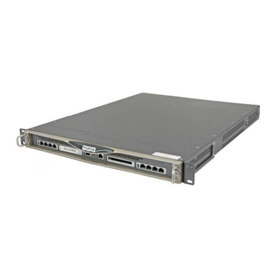
1 GB 2 GB The IP560 is a one rack-unit appliance that incorporates a serviceable slide- out tray into the chassis design. In its base configuration, the IP560 consists Solid state IDE compact flash storage, which stores the IPSO operating system... -
Page 21: Managing The Nokia Ip560 Security Platform
You can purchase optional 2.5-inch hard-disk drives to use for logging. You can also purchase an optional PC card for logging. The IP560 security platform is designed to meet other mid- to high-end availability requirements, including port density for connections to redundant internal, external, DMZ, and management networks. -
Page 22: Nokia Ip560 Security Platform Overview
Security Platform” on page 52. The IPSO command-line interface (CLI)—an SSHv2-secured interface that enables you to easily configure Nokia IP security platforms from the command line. Everything that you can accomplish with Network Voyager—manage, monitor, and configure the IP560 security platform—... -
Page 23: Four-Port 10/100/1000 Ethernet Nic
Nokia IP560 Security Platform Overview Figure 1 Component Locations Front View System status LEDs PMC NIC slots PC-card slot (slot 3) (slots 1 and 2)—unpopulated in base bundle IP560 SLOT 1 SLOT 2 SLOT 3 SLOT 4 00350 Console port... -
Page 24: Pmc Expansion Slots
Cables that connect to the Ethernet card must be compliant with IEEE 802.3ab, Cat 5E, or Cat 5 cables to prevent potential data loss. PMC Expansion Slots The IP560 security platform provides two additional PMC expansion slots for NIC options, as described in Table... -
Page 25: Console Port
Nokia products only support NICs purchased from Nokia or Nokia- approved resellers. The Nokia Global Support Services group can only provide support for Nokia products that use Nokia-approved accessories. For sales or reseller information, contact a Nokia service provider listed in “Nokia Contact Information” on page 3. -
Page 26: Auxiliary Port
One RJ-45 termination has a retractable shroud that releases or secures the RJ-45 tab. Use this end of the cable when connecting to the console port of the IP560. You can easily remove the console cable by pulling back on the shroud. -
Page 27: System Status Leds
DB-25 Pin Signal System Status LEDs You can visually monitor the status of the IP560 security platform by checking the system status LEDs. The system status LEDs are located on the center of the front panel, as shown in Figure... -
Page 28: Figure 5 Nokia Ip560 Security Platform System Status Leds
Overview Figure 5 Nokia IP560 Security Platform System Status LEDs Warning (yellow) Power indicator System OK Fault (red) (blue) (green) SLOT 2 SLOT 3 SLOT 4 00351 Table 5 shows the system status LEDs and describes their meaning. Table 5 System Status LEDs... -
Page 29: Logging Options
Each hard-disk drive provides 40 GB of disk storage. The hard-disk drives are not included in the standard package. When you purchase your IP560, you can order one or two hard disk drives for factory installation or order them later and install them yourself, as described in “Installing a Hard-Disk Drive”... -
Page 30: Using Pc Card For Logging
Overview Using PC Card for Logging The IP560 has a single PC-card slot that can support a PC card with 1 GB flash memory. The slot is labeled PCMCIA and is located on the front panel of the security platform, as Figure 6 shows. -
Page 31: Power Supply
Power supply Power Supply The IP560 supports one power supply. The power supply is autosensing and can accept input voltages between 47Hz-64Hz and 85VAC-264VAC. The power supply output is regulated to a tolerance of ± 5 percent of the specified output voltage. -
Page 32: Fan Unit
Fan Unit The IP560 fan is a single unit made up of four individual fans to provide the air flow required to maintain a proper operating temperature. The fan unit can provide proper airflow for a short time even if an individual fan fails. -
Page 33: Site Requirements, Warnings, And Cautions
“System Status LEDs” on page 27. Site Requirements, Warnings, and Cautions Before you install a Nokia IP560 security platform, ensure that your computer room or wiring closet conforms to the environmental specifications listed in Appendix A, “Technical Specifications.” Warning Excessive electromagnetic interference (EMI) can occur if you use controls, make performance adjustments, or follow procedures that are not described in this document. -
Page 34: Software Requirements
Warning On Nokia IP560 security platforms intended for shipment outside of the United States, the cord set might be optional. If a cord set is not provided, use a power cord rated at 10A, 250V, maximum 15 feet long, made of HAR cordage and IEC fittings approved by the country of end use. -
Page 35: Product Disposal
These devices contain materials and components that must be disposed of properly. Therefore, to help prevent damage to the environment, Nokia encourages you to dispose of these devices in an environmentally-friendly manner. - Page 36 Overview IP560 Security Platform Installation Guide...
-
Page 37: Installing The Nokia Ip560 Appliance
Installing the Nokia IP560 Appliance This chapter describes how to install the IP560 appliance. The following topic is discussed: Before You Begin Rack-Mounting the Appliance Before You Begin To rack-mount the appliance, you need: Phillips-head screwdriver Grounding wrist strap Suitable, grounded work surface on which to place the chassis tray... -
Page 38: Rack-Mounting The Appliance
Installing the Nokia IP560 Appliance Rack-Mounting the Appliance The Nokia IP560 security platform mounts in a standard 19-inch equipment rack with four mounting screws, as Figure 10 shows. Note To avoid damaging your equipment, Nokia recommends that you use all four rack-mounting bolts when you install your appliance on the rack. - Page 39 2. Optionally, remove the fan unit from the back of the appliance to lighten a. Locate the fan unit and the two retaining screws that secure it on the back of the IP560. 00353 Fan unit b. Loosen the retaining screws by turning them counterclockwise. IP560 Security Platform Installation Guide...
- Page 40 3. Optionally, remove the power supply from the rear of the appliance to lighten it, as shown in the illustration above. a. Locate the power supply on the back of the IP560 and the two screws that secure it. 00353...
- Page 41 4. Optionally, remove the chassis tray assembly from the appliance. a. Loosen the two chassis tray assembly retaining screws from the front panel of the appliance. IP560 SLOT 1 SLOT 2 SLOT 3 SLOT 4 00354 Chassis tray assembly retaining screws IP560 Security Platform Installation Guide...
- Page 42 Installing the Nokia IP560 Appliance b. Press the latch on the right to release the chassis tray assembly. SL OT SL OT SL OT SL OT 00520 c. Slide the chassis tray assembly forward and pull it entirely out of the appliance.
- Page 43 6. Mount the appliance into a standard 19-inch rack by using the mounting screws located on the mounting brackets. You can use the rear brackets for additional chassis support. For more information, see the Nokia IP560 Appliance Feature and Installation sheet that accompanied your IP560 appliance.
- Page 44 Installing the Nokia IP560 Appliance IP560 Security Platform Installation Guide...
-
Page 45: Performing The Initial Configuration
Performing the Initial Configuration The first time you turn on power to a Nokia IP560 security platform, the initial configuration process begins. This process enables you to configure the network settings and provides access to the admin account. You can perform the initial configuration in two ways: Configure a DHCP server to provide the initial configuration information the first time the appliance is started. -
Page 46: Using A Console Connection
Components.” Using a Console Connection If you do not use DHCP to perform the initial configuration of your Nokia IP560 security platform, you must use a serial console connection (cable included). After you perform the initial configuration, you no longer need the console connection. -
Page 47: Connecting Power And Turning The Power On
Connecting Power and Turning the Power On port of the IP560. You can easily remove the console cable by pulling back on the shroud. If you connect the console port to a data communications equipment (DCE) device, use a straight-through cable. - Page 48 (115 VAC or 220 VAC [85 to 264]) and configures itself appropriately. 4. Check the power LED (the Nokia logo) on the front panel of the appliance to ensure that the power supply is operating correctly.
-
Page 49: Performing The Initial Configuration
3 for technical support. Performing the Initial Configuration If you do not use DHCP to perform the initial configuration of your Nokia IP560 security platform, you must use a serial console connection (cable included). After you perform the initial configuration, you no longer need the console connection. - Page 50 Performing the Initial Configuration connections and still do not see either the BOOTMGR> or Hostname? prompts, verify that the terminal or terminal emulator program settings are correct. If the settings are correct, contact your Nokia service provider as listed in “Nokia Contact Information”...
-
Page 51: Connecting Network Interfaces
Voyager to configure the remaining network ports. Connecting Network Interfaces Connect at least one network interface to the network to use as the Nokia Network Voyager system-management interface. This interface is configured during the initial configuration process, which is described in Chapter 3, “Performing the Initial Configuration.”... -
Page 52: Using Nokia Network Voyager To Manage Your Security Platform
“Multi-Mode Fiber-Optic Gigabit Ethernet NIC Features” on page 77. Using Nokia Network Voyager to Manage Your Security Platform Use Nokia Network Voyager to configure and monitor your IP560. For additional information about how to use Network Voyager, see “Accessing Nokia Network Voyager Reference Information”... -
Page 53: Accessing Nokia Network Voyager Reference Information
Using Nokia Network Voyager to Manage Your Security Platform Accessing Nokia Network Voyager Reference Information As you use Nokia Network Voyager, the Nokia Network Voyager Reference Guide and Voyager inline help are available for you to use. You can access both information sources from the Network Voyager interface, Figure 12 shows. -
Page 54: Nokia Network Voyager Inline Help
(see the doc folder). Nokia Network Voyager Inline Help You can access inline help when you use Nokia Network Voyager. Inline help is the context-sensitive information source for Network Voyager. To access inline help for a specific subject, click the Help icon next to the subject. -
Page 55: Using Nokia Horizon Manager
For more information about how to access and use the CLI, see the Nokia CLI Reference Guide for the version of IPSO you are using. Using Nokia Horizon Manager Nokia Horizon Manager is an extension of the Network Voyager management functionality. - Page 56 (MSP), or hosted applications service provider network (ASP). For information about how to obtain Horizon Manager or to learn more about the Horizon Manager, see the “Nokia Contact Information” at the beginning of this document. IP560 Security Platform Installation Guide...
-
Page 57: Installing And Replacing Network Interface Cards
Installing and Replacing Network Interface Cards Your Nokia IP560 security platform comes with any network interface cards (NICs) you ordered already installed. All NICs installed in the appliance are housed in PMC expansion slots. You should have a working knowledge of networking equipment before you attempt to service a appliance. -
Page 58: Deactivating Configured Interfaces
Deactivating Configured Interfaces If you are removing or replacing an installed NIC, use Nokia Network Voyager to deactivate any configured ports on the NIC before removing it. Deactivate all of the logical interfaces on the NIC. -
Page 59: Before You Begin
Voyager. For additional information, see “Deactivating Configured Interfaces” on page 58. Use these instructions to install a NIC in the IP560. Some steps are not applicable to all procedures. The instructions point out steps appropriate to each procedure. Before You Begin... - Page 60 4. Slide the chassis tray assembly forward, pressing the release tab on the right side of the assembly, and completely remove the chassis to expose the motherboard components. SL OT SL OT SL OT SL OT 00520 5. Place the chassis tray assembly on a table top. IP560 Security Platform Installation Guide...
- Page 61 S L O S L O 00440 If you are installing a NIC in an unoccupied slot, remove the blank bezel that occupies the space in the appliance front panel and retain it for future use. IP560 Security Platform Installation Guide...
-
Page 62: Assembly
S L O 00443 b. Gently push the back of the NIC down toward the chassis tray assembly. Make sure that the NIC edge is completely seated into the connectors on the chassis tray assembly. IP560 Security Platform Installation Guide... - Page 63 8. From the top of the chassis tray assembly, screw the NIC retaining screws into the standoffs on the back of the NIC. S L O S L O 00441 9. From beneath the chassis tray assembly, screw in the bezel retaining screws. IP560 Security Platform Installation Guide...
-
Page 64: Configuring And Activating Interfaces
12. Turn the power on. Configuring and Activating Interfaces The IP560 appliance automatically detects any new NIC when the appliance is restarted. Use Nokia Network Voyager to configure and activate the logical and physical interfaces on the NIC. IP560 Security Platform Installation Guide... -
Page 65: Monitoring Network Interface Cards
Use Network Voyager to access detailed port information. For information about accessing Network Voyager, see “Accessing Nokia Network Voyager Reference Information” on page 53. You can also use the IPSO tcpdump command to examine the track on a specific port. IP560 Security Platform Installation Guide... - Page 66 Installing and Replacing Network Interface Cards IP560 Security Platform Installation Guide...
-
Page 67: Connecting Pmc Network Interface Cards
Connecting PMC Network Interface Cards This chapter describes the network interface cards available for the Nokia IP560 security platform and how to connect those NICs to your network. The following NICs are described: Four-Port 10/100 Ethernet NIC Four-Port and Two-Port Copper Gigabit Ethernet NIC (10/100/1000) -
Page 68: Four-Port 10/100 Ethernet Nic
The IP560 supports Nokia-approved, four-port UTP5 dual-mode (10-Mbps and 100-Mbps) Ethernet NICs installed in a PMC expansion slot. When you purchase a 10/100 Ethernet NIC with your IP560, the NIC is installed before the appliance is delivered to you. For information about how to add or replace a NIC, see Chapter 4, “Installing and Replacing Network Interface Cards.”... -
Page 69: Figure 13 Four-Port 10/100 Ethernet Nic Front Panel Details
Activity LED (blinking green) After the power is turned on and the cables are connected, the Ethernet link LEDs on both the IP560 and on the remote equipment illuminate to indicate the connection. As data is transmitted, the activity LEDs on the appliance illuminate. -
Page 70: Ethernet Nic Connectors And Cables
RJ-45 cable. The connector is numbered from right to left, with the copper tabs facing up and toward you. Figure 14 Output Connector for the Ethernet Cable Assignment TX + TX - 00270 RX + RX - IP560 Security Platform Installation Guide... -
Page 71: Four-Port And Two-Port Copper Gigabit Ethernet Nic (10/100/1000)
Gigabit Ethernet NICs installed on a PMC expansion slot. The IP560 can accommodate up to four Gigabit Ethernet NICs. When you purchase a copper Gigabit Ethernet NIC with your IP560, the NIC is installed before the appliance is delivered to you. For information about how to add or replace a NIC, see Chapter 4, “Installing and Replacing... -
Page 72: Figure 16 Four-Port Copper Gigabit Ethernet Nic Front Panel
Compliance with IEEE 802.3ab Gigabit Ethernet specifications Cable autosensing The copper Gigabit NICs in the IP560 run on Nokia IPSO v4.0.1 or higher. You can configure and monitor Gigabit Ethernet NIC interfaces with Nokia Network Voyager. Specifically, you can use Network Voyager to set the port speed and full-duplex mode to 1000, 100, or 10 Mbps. -
Page 73: Figure 17 Two-Port Copper Gigabit Ethernet Nic Front Panel
These NICs are sold by Nokia under the order code NIF4425. After the power is turned on and the cables are connected, the Ethernet Link LEDs on both the IP560 and on the remote equipment illuminate to indicate the connection. -
Page 74: Copper Gigabit Ethernet Nic Connectors And Cables
(Cat 5 or Cat 5e type cable, or as required by your network configuration). Note Nokia copper Gigabit Ethernet NICs support cable autosensing. You can use a straight-through or crossover cable to connect the NIC to a Gigabit Ethernet hub or switch or to connect directly to a host. -
Page 75: Figure 18 Gigabit Ethernet Cable Connector Output Pin
Figure 18 Gigabit Ethernet Cable Connector Output Pin Assignments 1000 Mbps 10/100 Mbps Pin# Assignment Assignment BI_DA+ 00270 BI_DA- BI_DB+ BI_DC+ BI_DC- BI_DB- BI_DD+ BI_DD- To connect directly to a host, use an RJ-45 crossover cable wired as Figure 19 shows. IP560 Security Platform Installation Guide... -
Page 76: Two-Port Fiber-Optic Gigabit Ethernet Nic
Two-Port Fiber-Optic Gigabit Ethernet NIC The IP560 supports Nokia-approved, two-port, fiber-optic Gigabit Ethernet NICs installed on a PMC expansion slot. The IP560 can accommodate up to four Gigabit Ethernet NICs. When you purchase a Gigabit Ethernet NIC with your IP560, the NIC is installed before the appliance is delivered to you. -
Page 77: Multi-Mode Fiber-Optic Gigabit Ethernet Nic Features
Link speed auto advertising Tracing through tcpdump Compliance with IEEE 802.3z Gigabit Ethernet specification The MMF fiber-optic Gigabit Ethernet NICs in the IP560 run on Nokia IPSO v4.0.1 or higher. You can configure and monitor Gigabit Ethernet NIC interfaces with Nokia Network Voyager. -
Page 78: Fiber-Optic Gigabit Ethernet Nic Connectors And Cables
NICs, and two LC-to-SC cables are included with two-port fiber-optic Gigabit Ethernet NICs. You can order additional cables from a cable vendor of your choice. Caution Cables that connect to the Gigabit Ethernet NIC must be IEEE 802.3z compliant to prevent potential data loss. IP560 Security Platform Installation Guide... -
Page 79: Using The Boot Manager
Using the Boot Manager The Nokia IP560 security platform incorporates a boot manager to control the boot-up process. The boot manager allows you to perform a number of tasks, including: Booting from IPSO kernel Installing new versions of Nokia IPSO (the operating system) -
Page 80: Variables
Default is three seconds. boot-file Name of the operating system kernel file. Default is /image/current/kernel. boot-flags String of flags passed to the kernel. Default is -x. boot-device Device from which the boot-file loads. Default is wd0. IP560 Security Platform Installation Guide... -
Page 81: Viewing The Variables And Other System Parameters
Verbose mode—verbose during device probing and thereafter. Viewing the Variables and Other System Parameters printenv Use the printenv command to view the values of variables currently stored in the boot manager nonvolatile memory. The command has the following syntax: printenv IP560 Security Platform Installation Guide... -
Page 82: Sysinfo
/image/current/kernel boot-flags: boot-device: vendor: Nokia model: bmslice: BOOTMGR[12]> sysinfo Use the sysinfo command to view system information such as CPU speed and memory size. This command has the following syntax: sysinfo IP560 Security Platform Installation Guide... - Page 83 0:a0:8e:a4:fa:f speed 1000M full duplex eth-s3p2: flags=130<BROADCAST,MULTICAST,PRESENT> ether 0:a0:8e:a4:fa:10 speed 1000M full duplex eth-s3p3: flags=130<BROADCAST,MULTICAST,PRESENT> ether 0:a0:8e:a4:fa:11 speed 1000M full duplex eth-s3p4: flags=131<LINK,BROADCAST,MULTICAST,PRESENT> ether 0:a0:8e:a4:fa:12 half duplex loop0: flags=10b<UP,LINK,LOOPBACK,PRESENT> soverf0: flags=2923<UP,LINK,MULTICAST,PRESENT,IPV6ONLY> stof0: flags=2903<UP,LINK,PRESENT,IPV6ONLY> tun0: flags=107<UP,LINK,POINTOPOINT,PRESENT> BOOTMGR[3]> IP560 Security Platform Installation Guide...
-
Page 84: Setting The Variables
Using the Boot Manager Use the ls command to view the contents of directories on the devices in your IP560. The command has the following syntax: ls device directory where device is the device that contains the directory you want to look at, and directory is the directory on that device. -
Page 85: Unsetenv
The command has the following syntax: set-defaults name where name is the name of the variable to be set to its factory default. If name is not specified, all variables are set to their factory defaults. IP560 Security Platform Installation Guide... -
Page 86: Setalias
Use the unsetalias command to clear an alias. The command has the following syntax: unsetalias name where name is the name of the alias to be cleared. For example, the following command deletes the alias from the list of disk aliases: BOOTMGR[2]> unsetalias disk IP560 Security Platform Installation Guide... -
Page 87: Other Commands
Booting the System The boot command lets you boot up the Nokia IPSO operating system. It allows you to set the boot device, boot file, and boot flags from the command line. The command has the following syntax:... -
Page 88: Using The Boot Manager To Install Nokia Ipso
(compact flash) boot-file /image/current/kernel boot-flags Using the Boot Manager to Install Nokia IPSO Use the install command to install Nokia IPSO. The syntax of the command install For complete installation procedures, see the appropriate version of release notes. Note Using the install command to perform a full installation deletes the... -
Page 89: Protecting The Boot Manager With A Password
Protecting the Boot Manager with a Password To prevent accidental or unauthorized access to the hard disk on your Nokia IP560 security platform, you can require that the user enter a password to access the boot manager install command. Use the... -
Page 90: Installing The Boot Manager
Nokia IPSO (the operating system), not from the boot manager. To install the new boot manager, at the Nokia IPSO command prompt enter: /etc/install_bootmgr wd1 /image/current/bootmgr/nkipflash The command installs the new boot manager image (nkipflash) into the flash device (wd1). - Page 91 Nokia Customer Support site as listed in “Nokia Contact Information” page 3. 2. At the Nokia IPSO command prompt, enter: /etc/upgrade_bootmgr wd0 /etc/nkipflash The command upgrades the boot manager with the new image (nkipflash), writing it into the internal compact flash (wd0). The upgrade takes some time to complete.
- Page 92 Using the Boot Manager IP560 Security Platform Installation Guide...
-
Page 93: Troubleshooting
IP560. If this is not possible using your laptop computer or terminal, the problem is with the terminal or cable and not the appliance. - Page 94 Solution Verify terminal settings: 8 data, 1 stop, no parity, 9600 bps. Problem Terminal set for flow control. Solution The IP560 does not use flow control. The terminal should be set for no flow control. Problem Defective IP560 or file system.
- Page 95 The two double quotation marks at the end of the command properly indicate a blank password. After you execute this command, the system reports that the password was not successfully changed. However, the password is changed and is now newpassword. IP560 Security Platform Installation Guide...
- Page 96 3. Create the new default configuration. Do Not Get a Login Prompt—Error Messages Appear Problem The IP560 is defective, or the file system on the IP560 is defective. Solution Contact the Nokia customer support site listed in “Nokia Contact...
- Page 97 Do Not See Interfaces that Should be Present Problem Local IP560 ports do not appear. Solution Your NIC might be defective. Contact the appropriate Nokia customer support site as listed in “Nokia Contact Information”...
- Page 98 Device Problem No link light. Solution You might have used the wrong cable. Use a crossover cable between an IP560 and a host, and a straight-through cable between an appliance and a hub. Problem Solid data and activity LED. Solution You might have set the wrong speed. Verify that the speeds match on each end of the Ethernet connection (10 Mbps or 100Mbps).
- Page 99 4. Click Delete for the entry you want to delete. 5. Click Apply. Problems with Multicast Use tcpdump to view packets. To display packets for a specific interface, use the following command: tcpdump . For more -i interface proto igmp IP560 Security Platform Installation Guide...
- Page 100 Troubleshooting information about how to use the tcpdump command, see the Nokia Network Voyager Reference Guide. Under Routing Options in the Routing Configuration section in Network Voyager, you can also enable several types of trace options for DVMRP. These traces are logged into /var/tmp/ipsrd.log...
- Page 101 Solution Set encapsulation to LLC/SNAP. Consult your 1483 device documentation. Problem The MTU size is not 1500. Solution The MTU size must be 1500. Nokia does not support larger MTU sizes. Appliance Not Receiving Power Problem Power cord is not properly plugged in.
- Page 102 Troubleshooting Appliance locks up after you upgrade Nokia IPSO with a console connection. No error messages appear, but the appliance stops responding to console and network. Problem During the upgrade process, some of the environment variables might not have updated correctly.
-
Page 103: Troubleshooting Routing Problems
ICLID (IPSRD command-line interface daemon) command. An example use of the ICLID command is shown below. For information about the ICLID command, see the Nokia Network Voyager Reference Guide. For information about how to access Network Voyager and the related reference materials, see “Accessing Nokia Network Voyager... - Page 104 0 172.16/16 via 10.1.1.225, eith-sp4p1c0,cost 3, age 3111 In addition, several trace options are available. You can enable these options under the routing options in Network Voyager. When a trace is enabled the output appears in /var/tmp/ipsrd.log. IP560 Security Platform Installation Guide...
- Page 105 -i interface proto ospf For more information about how to use the tcpdump command, see the Nokia Network Voyager Reference Guide. Under routing options in Network Voyager, you can also enable several types of trace options for OSPF.
- Page 106 -i interface proto rip For more information about how to use the tcpdump command, see the Nokia Network Voyager Reference Guide. Under routing options in Network Voyager, you can also enable several types of trace options for routing information protocol (RIP).
- Page 107 53. Problem Routing protocol is not functioning properly. Solution to ensure that each routing protocol is functioning properly, see “Common Problems with OSPF” on page 105 and “Common Problems with RIP” on page 106. IP560 Security Platform Installation Guide...
- Page 108 Troubleshooting IP560 Security Platform Installation Guide...
-
Page 109: Replacing Other Components
Chapter 4, “Installing and Replacing Network Interface Cards.” You should have a working knowledge of networking equipment before you attempt to service an IP560 appliance. Limit service of the appliance to the procedures described in this chapter. Note To protect the IP560 appliance and the memory modules from electrostatic discharge damage, make sure you are properly grounded before you touch these components. -
Page 110: Replacing The Compact Flash Memory Card
(slot B). Figure 21 shows the location of the compact flash memory card. Figure 21 Compact Flash Memory Card Slot SL O SL O SL O SL O 00523 IP560 Security Platform Installation Guide... - Page 111 You risk damage to the appliance or loss of data if you do not use the following procedure when you replace the compact flash memory. 1. Use Nokia Network Voyager or the command-line interface (CLI) to perform an orderly shutdown of the IP560 appliance.
- Page 112 4. Slide the chassis tray assembly forward, pressing the release tab on the right side of the assembly, and completely remove the chassis to expose the motherboard components. SL OT SL OT SL OT SL OT 00520 5. Place the chassis tray assembly on a table top. IP560 Security Platform Installation Guide...
- Page 113 6. Locate and remove the existing compact flash card from the slot by gently sliding it out of the slot. SL OT SL OT SL OT SL OT 00522 7. Gently insert the new compact flash card into the slot. IP560 Security Platform Installation Guide...
-
Page 114: Installing And Using A Pc Card
Installing and Using a PC Card Figure 22 shows the external PC card location. Figure 22 External PC Card Location IP560 SLOT 1 SLOT 2 SLOT 3 SLOT 4 00350 Eject PCMCIA PC button card slot IP560 Security Platform Installation Guide... - Page 115 2. Press gently on the card until it is firmly seated in the slot. The eject button to the left of the slot should be flush with the card. 3. Open Nokia Network Voyager and configure the PC card as an optional disk by using Network Voyager.
-
Page 116: Installing A Hard-Disk Drive
40 GB of storage space. The hard-disk drives are not included in the standard package. When you purchase your IP560, you can order one or two hard disk drive(s) for factory installation or order them later and install them yourself, as described in this chapter. -
Page 117: Before You Begin
To install or replace a hard-disk drive, you need: Physical access to the appliance or gateway Nokia hard-disk drive kit and accompanying supplement A Phillips-head screwdriver The following procedure requires removing the chassis tray assembly from the chassis. - Page 118 If you fail to use the following procedure when you remove the hard- disk drive, the drive might become damaged or you might lose data. 1. Use Nokia Network Voyager or the command-line interface (CLI) to perform an orderly shutdown of the IP560 appliance.
- Page 119 4. Slide the chassis tray assembly forward, pressing the release tab on the right side of the assembly, and completely remove the chassis to expose the motherboard components. SL OT SL OT SL OT SL OT 00520 5. Place the chassis tray assembly on a table top. IP560 Security Platform Installation Guide...
-
Page 120: Figure 23 Location Of Hard-Disk Drive On Chassis Tray
Figure 23 Location of Hard-Disk Drive on Chassis Tray Assembly Slot A SL OT SL OT Slot B SL OT SL OT 00352 Note In single hard-drive configurations, install the hard-disk in Slot A first. IP560 Security Platform Installation Guide... - Page 121 Installing a Hard-Disk Drive 6. Remove the four screws from the base of the hard-disk drive and remove the hard-disk drive. 00445 IP560 Security Platform Installation Guide...
- Page 122 Replacing Other Components 7. Slide the new hard-disk drive onto the mounting locations. 00355 IP560 Security Platform Installation Guide...
- Page 123 8. Replace the four screws. 00445 9. Slide the chassis tray assembly back into the appliance until it clicks into place. SL O SL O SL O SL O 00359 10. Resecure the two chassis tray assembly retaining screws. IP560 Security Platform Installation Guide...
-
Page 124: Replacing Or Upgrading Memory
Nokia-approved memory upgrade kit. The IP560 comes with 1 GB of RAM in two 512 MB DIMMs and can be upgraded to 2 GB of RAM by the addition of a pair of 512 MB DIMMs. -
Page 125: Figure 24 Dimm Socket Locations
You must install DIMMs in pairs starting from the left. Insert a pair of DIMMS into adjacent slots J1/J2 and/or J3/J4, otherwise the DIMMS do not work. You can also use all four slots at one time. IP560 Security Platform Installation Guide... -
Page 126: Before You Begin
To upgrade or replace your appliance memory, you need: Physical access to the appliance Nokia memory upgrade kit and accompanying supplement Access to the appliance by using Nokia Network Voyager or command- line interface (CLI) A Phillips-head screwdriver Grounding wrist strap... - Page 127 SL OT SL OT SL OT SL OT 00520 5. Remove the DIMM by pressing the two retaining clips outward and carefully pulling each DIMM upward. IP560 Security Platform Installation Guide...
- Page 128 The top of the DIMM is smooth. The bottom edge has two different- length sets of contacts, which mate with the slots on the socket. Be sure the contacts and slots are properly aligned before you insert the DIMM. IP560 Security Platform Installation Guide...
- Page 129 Replacing or Upgrading Memory The retaining clips move into the lock position as you press the DIMM into place. SL O SL O SL O SL O 00511 IP560 Security Platform Installation Guide...
-
Page 130: Replacing A Nokia Encryption Accelerator Card
VPN performance. The IP560 appliance uses a PMC format accelerator card. The accelerator card has no external connections and requires no cables. The accelerator card software package is part of IPSO, so the appliance automatically detects and configures the card. -
Page 131: Before You Begin
Replacing a Nokia Encryption Accelerator Card Use Nokia Network Voyager to configure your software applications (IPSec or Check Point VPN) to make use of the available hardware accelerator. For information about how to configure software applications, see “Configuring Software to Use Hardware Acceleration”... - Page 132 Replacing Other Components To replace the accelerator card 1. Use Nokia Network Voyager or the command-line interface (CLI) to perform an orderly shutdown of the IP560. For information about how to access Network Voyager and the related reference materials, see “To open Nokia Network Voyager”...
- Page 133 Replacing a Nokia Encryption Accelerator Card 4. Slide the chassis tray assembly forward, pressing the release tab on the right side of the assembly, and completely remove the chassis to expose the motherboard components. SL OT SL OT SL OT...
- Page 134 5. Locate the PMC encryption accelerator card on the motherboard. The encryption card is located on the back left side of the motherboard. SL O SL O SL O SL O 00361 6. Loosen the four retaining screws and remove the card. 00517 IP560 Security Platform Installation Guide...
- Page 135 Replacing a Nokia Encryption Accelerator Card Caution Do not use the PMC connectors located at the front of the motherboard for the acceleration card. Those connectors are for the NICs. 7. Position the three male PMC connectors on the card over the three female PMC connectors on the motherboard.
- Page 136 SL O SL O SL O SL O 00359 12. Configure your software to use hardware acceleration by following the instructions in “Configuring Software to Use Hardware Acceleration” page 137. IP560 Security Platform Installation Guide...
-
Page 137: Configuring Software To Use Hardware Acceleration
Replacing a Nokia Encryption Accelerator Card Configuring Software to Use Hardware Acceleration Use Nokia Network Voyager to configure virtual private network (VPN) tunnels to use hardware acceleration. This step is necessary for the optional encryption accelerator card on the IP560 appliance. -
Page 138: Replacing A Fan Unit
To replace a fan unit 1. Use Nokia Network Voyager or the command-line interface (CLI) to perform an orderly shutdown of the IP560. For information about how to access Network Voyager and the related reference materials, see “To open Nokia Network Voyager”... - Page 139 Replacing a Fan Unit 3. Locate the fan unit on the back of the IP560 appliance and the two retaining screws that secure it. 00353 Retaining screws 4. Loosen the retaining screws by turning them counterclockwise. 5. Slowly pull the fan unit out of the chassis toward the rear.
-
Page 140: Replacing A Power Supply
Integrated power supply Power supply switch cooling fan Caution You should have working knowledge of networking equipment before you attempt to service an appliance or gateway. Limit service to the procedures described in this document. IP560 Security Platform Installation Guide... - Page 141 To replace a power supply 1. Use Nokia Network Voyager or command-line interface (CLI) to perform an orderly shutdown of the IP560 appliance. For information about how to access Network Voyager, see...
-
Page 142: Monitoring The Ip560 Appliance Power Supply
10. Reinstall the two retaining screws. 11. Turn on the power. Monitoring the IP560 Appliance Power Supply You can monitor the status of the IP560 appliance power supply with Nokia Network Voyager. Similarly, you can also use the command-line interface IP560 Security Platform Installation Guide... -
Page 143: Replacing The Battery
Network Voyager, see the Nokia Network Voyager Reference Guide or use the Network Voyager inline help. To monitor the IP560 appliance power supply by using Nokia Network Voyager 1. Log on to the IP560 appliance with Network Voyager. - Page 144 To install the battery, perform the following tasks: 1. Use Nokia Network Voyager or the command-line interface (CLI) to perform an orderly shutdown of the IP560. For information about how to access Network Voyager and the related reference materials, see “To open Nokia Network Voyager”...
- Page 145 SL OT SL OT SL OT SL OT 00520 5. Place the chassis tray assembly on a table top. 6. Locate the battery on the motherboard. IP560 Security Platform Installation Guide...
- Page 146 8. With the positive side facing up, slide the new battery through the cutout in the battery holder. Caution You must place the new battery into the battery holder observing the correct polarity. The positive terminal of the battery must be facing up. IP560 Security Platform Installation Guide...
- Page 147 “Nokia Contact Information” on page 3. 12. Reset the appliance date and time information by using Nokia Network Voyager or the command-line interface. The battery is required to maintain the date and time whenever you shut down the appliance.
- Page 148 Replacing Other Components IP560 Security Platform Installation Guide...
-
Page 149: A Technical Specifications
3.5 in. (8.89 cm) Width: 17 in. (44 cm) 19 in. (48 cm) rack-mountable Depth: 26 in. (53.34 cm) Operational 0° C to +40° C (32° F to 104° F) Temperature Humidity 5% to 85% IP560 Security Platform Installation Guide... -
Page 150: Space Requirements
19-inch rack. Each IP560 requires the following space in a rack: 3.5 inches (8.89 centimeters) of vertical space 28 inches (71 centimeters) behind the front-panel of the rack 6 inches (15 centimeters) behind the IP560 to allow the back exit fan to move air through the appliances Caution Do not block the ventilation holes on the IP560. -
Page 151: B Compliance Information
Declaration of Conformity According to ISO/IEC Guide 22 and EN 45014: Manufacturer’s Name: Nokia, Inc. Manufacturer’s Address: 313 Fairchild Drive Mountain View, CA 94043-2215 declares that the product: Product Name: IP560 Model Number: EM7800 Product Options: IP560 Security Platform Installation Guide... - Page 152 Directive 89/336/EEC with Amendment 93/68/EEC. Christopher Saleem Compliance & Reliability Engineering Manager Security & Mobile Connectivity, Enterprise Solutions Mountain View, California November 2005 Elie Habib Senior Vice President Security & Mobile Connectivity, Enterprise Solutions Mountain View, CA IP560 Security Platform Installation Guide...
-
Page 153: Compliance Statements
European Community (CE) EN61000-4-5 European Community (CE) EN61000-4-6 European Community (CE) EN61000-4-11 European Community (CE) Harmonics and Voltage Fluctuation EN61000-3-2 European Community (CE) EN61000-3-3 European Community (CE) Safety Standards UL60950/EN60950 US/European Community(CE) CAN/CSA-C22.2 No.60950 Canada IP560 Security Platform Installation Guide... -
Page 154: Fcc Notice (Us)
Consult the dealer or an experienced radio/TV technician for help. Caution Any changes or modifications not expressly approved by the grantee of this device could void the user’s authority to operate the equipment. 050316 www.anatel.gov.br IP560 Security Platform Installation Guide... - Page 155 26 setenv 84 sysinfo 82 unsetalias 86 unsetenv 85 base bundle 20 compact flash card 20 battery replacing 110 holder 146 compliance information 151 location 146 compliance statements 153 replacing 143 IP560 Security Platform Installation Guide Index - 155...
- Page 156 129 front panel 22 socket locations 125 disk storage 29 diskless 29 green LED 32 DMZ 21 grounding cable 141 document structure 13 dual inline memory-module sockets (DIMMs) 124 halt command 87 Index - 156 IP560 Security Platform Installation Guide...
- Page 157 LC connector 51, 78 Nokia Horizon Manager 22 LEDs null-modem cable 46 power supply 32 system status 27 log files, storing 116 opening Network Voyager 52 logging 21 operating system requirements 34 hard-disk drives 29 IP560 Security Platform Installation Guide Index - 157...
- Page 158 Gigabit Ethernet 24 recycling retired equipment 35 two-port fiber-optic Gigabit Ethernet 24, 77 red LED 28, 32 release tab 112 reset button 20 unicast traffic 21 retaining clips, DIMM 129 unsetalias command 86 RJ-45 Index - 158 IP560 Security Platform Installation Guide...
- Page 159 34 ventilation holes 150 vertical space requirements 150 virtual private network 137 voltage 31 voltage fluctuation 153 VPN performance 130 VT100-compatible terminal 46 warning notices 14 width 149 yellow LED 28, 32 IP560 Security Platform Installation Guide Index - 159...
- Page 160 Index - 160 IP560 Security Platform Installation Guide...
Need help?
Do you have a question about the IP560 and is the answer not in the manual?
Questions and answers