Table of Contents
Advertisement
InstallatIon InstructIons and owner's Manual
Model 3651-372
Installation Instructions
and owner's Manual
IMportant notIce!
read the enclosed instructions carefully before installing/
operating this garage door opener. pay close attention to all
warnings and notes. this manual Must be attached to the
wall in close proximity to the garage door opener.
© Copyright 2004, 2005, 2006 Wayne-Dalton Corp.
Part No. 305871
Rev 7
6/6/2006
Advertisement
Table of Contents
Troubleshooting

Related Manuals for Wayne-Dalton IDrive 3651-372


Summary of Contents for Wayne-Dalton IDrive 3651-372
- Page 1 InstallatIon InstructIons and owner’s Manual Model 3651-372 Installation Instructions and owner’s Manual IMportant notIce! read the enclosed instructions carefully before installing/ operating this garage door opener. pay close attention to all warnings and notes. this manual Must be attached to the wall in close proximity to the garage door opener.
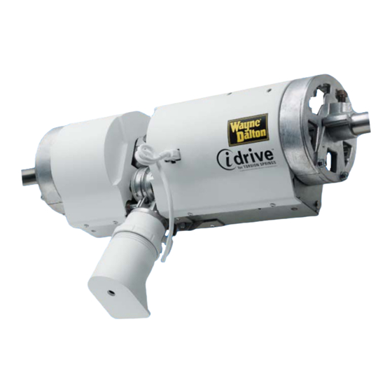
- Page 2 How idrive worKs idrive mounts to the lift cables raise door security arm manually locks counterbalance above door. from bottom. closed door. Mounts on tHe wall Instead oF clutterInG tHe ceIlInG...
-
Page 3: Package Contents
Package Contents Opener Cable Keeper Assemblies Safety Sensors with Hardware 5 Button Wireless (2: 1 Sender + 1 (2: 1 Right + 1 Left) Keyless Entry Receiver) Three labels & Three manual labels & not shown manual Three not shown labels &... - Page 4 By design, this opener will detect obstructions and reverse rather than force the door through obstructions. to ensure your new idrive® opener works as intended, your garage door must be installed and balanced properly. Before installing your garage door opener, open and close your door manually to ensure that it operates smoothly from top to bottom.
- Page 5 30-3/8” Track Top of door Pre-Installation Inspection Two electrical outlets are recommended for the idrive installation. One of these outlets needs to be located less than 6’ from the Before installing the torsion idrive Opener, ensure your door system ®...
-
Page 6: Tools Needed
Note: If your Torsion Spring does not match one of the Pre-Installation Inspection following Torsion Springs you may not install this idrive. Possible Spring Locations 30-3/8” NOTE: Option 4 depicts an EZ-Set™ torsion spring system. EZ-Set™ torsion spring system is a registered trademark of Clopay Building ®... - Page 7 SEVERE OR FATAL INJURY. Pre-Installation Inspection ..............II-III. FOLLOW THESE INSTRUCTIONS Tools Needed ..................III. CAREFULLY. Important Safety Instructions .............. IV. IMPORTANT SAFETY Torsion idrive Installation ..............1-16. INSTRUCTIONS Pre-Operation Installation ..............17-25. 1. READ AND FOLLOW ALL INSTALLATION INSTRUCTIONS. Operation .................... 26-31. 2. D o not connect the Opener to electrical power until Maintenance ..................31.
-
Page 8: Preparing For Installation
Mounting Surface Preparing for Installation (2’ x 6” Recommended) a. If the header does not provide a Tools Needed: Tools Needed: mounting surface for the Opener, a None proper mounting surface will need to be installed. Securely fasten a wood mounting surface (2”... - Page 9 Lubricating Gear Assemblies Lubricate both right hand and left Tools Needed: Grease Torsion hand Gear Assembly teeth with the Packet Tube None grease provided. Apply grease along the Torsion Tube where the Opener will mount. Installing Opener Place the Opener over the Torsion Tube Tools Needed: and between the two Gear Assemblies.
- Page 10 Positioning Opener Lift the Opener slightly and slide the Tools Needed: Right Hand Gear Assembly over so the 3/8” Wrench Right Hand Drive Gear meshes with and Square rests on the teeth of the Right Hand Gear Head Bolt Assembly. Position Gear Assembly so it is 1/8”...
- Page 11 Securing Mounting Bracket Secure the Mounting Bracket to the Tools Needed: Mounting Surface by first pre-drilling the Drill with 3/16” bit Lag Screw locations with a 3/16” 7/16” Socket Driver diameter bit and fastening with (2) 5/16” x 1-5/8” Lag Screws. (2) 5/16”...
- Page 12 Attaching Disconnect Cables Attach the loose Disconnect Cable, from Tools Needed: the hardware kit, to the attached Pliers Disconnect Cable using the “S” Hook. Close both ends of the “S” Hook to lock the cables together. Close S-Hook Threading Disconnect Cable Guide Bracket Thread the Disconnect Cable Guide Tools Needed:...
- Page 13 Attaching Disconnect Cable Guide Bracket Tools Needed: Position the flange of the Disconnect Cable Guide Bracket just inside the Cable Drill with 1/8” bit Drum. Align the Disconnect Cable so it 7/16” Socket remains parallel to the Torsion Tube. Driver When installing Opener, ensure there is at least 6”...
- Page 14 Mounting Disconnect Handle Bracket Mark a location on the right jamb, 6 feet Opener Tools Needed: Tools Needed: above the floor to mount the Disconnect Pencil Handle Bracket. Align top of the Bracket Tape measure with the mark. Drill pilot holes using 1/8” drill bit.
- Page 15 Positioning Safety Sensor Wall Mounting Brackets Select and mark with a pencil, a Tools Needed: mounting position no more than 5 inches Pencil above the floor to center line of wall Tape measure mounting bracket. The Safety Sensors should be mounted as close to the door Wall Mounting Bracket track or inside edge of the door as...
- Page 16 Attaching Safety Sensors Attach the Sending and Receiving Safety Tools Needed: Sensors to the “U” Brackets by inserting None all three tabs into the respective holes. IMPORTANT! Identify which side of the garage door is exposed to the most sunlight. Mount the Sending Unit (Unit without LED) on the side which is exposed to the most sun.
- Page 17 Connecting Safety Sensor Wires to Opener Tools Needed: Expose the Terminal Block by sliding the right hand Gear Assembly to the right. Wire cutters Using a pair of Needle Nose Pliers, gently Flat Tip pull terminal block from right hand side of Screwdriver opener.
- Page 18 Positioning Wall Station WARNING Tools Needed: TO PREVENT POSSIBLE INJURY, INSTALL Tape Measure ALL WALL CONTROLS OUT OF THE Drill REACH OF CHILDREN AND IN A 3/32” Drill Bit LOCATION WHERE THE OPENER CAN BE SAFELY ACTIVATED, WHILE KEEPING 3/16” Drill Bit DOOR IN SIGHT.
- Page 19 Mounting Wall Station (Continued) CAUTION: Over tightening the upper Tools Needed: screw could deform plastic case and may Phillips Head affect operation. Screwdriver Once wall station is snuggly onto lower screw, install upper screw. Do not over tighten. Phillips Head Screw Installing Battery Wall Station Remove the Battery Cover (right-hand side...
- Page 20 Installing Cable Keepers Carefully inspect the cables on your door. Tools Needed: If they are worn, frayed or broken, contact None a qualified door service company to replace the cables before installing the cable keepers. WARNING OPERATING A DOOR WITH FRAYED OR Spacer BROKEN COUNTERBALANCE CABLES CAN RESULT IN SEVERE OR FATAL INJURY.
- Page 21 Installing Cable Keepers Cable Keeper Assembly (Continued) Tools Needed: Fasten the Cable Keeper Assemblies with Drill with 1/8” bit (2) 1/4 x 11/16” self drilling screws (wood doors will use (2) 1/4 x 1” lag screws). 7/16” Socket Driver Once the Cable Keeper Assemblies are secured to the section, place the Plastic (2) 1/4 x 11/16”...
- Page 22 Positioning the Light Fixture WARNING Tools Needed: Phillips head TO AVOID ELECTRICAL SHOCK screwdriver DISCONNECT POWER TO THE RECEPTACLE AT THE FUSE/BREAKER Flat Tip BOX, BEFORE PROCEEDING WITH THE Screwdriver INSTALLATION OF THE LIGHT FIXTURE. Receptacle Cover IMPORTANT! This light fixture has a grounding type plug with a third (grounding) pin.
- Page 23 Attaching Diffuser Power Outlet Light Fixture Tools Needed: Screw a 75W (maximum) light bulb into Light Socket and snap Diffuser into Light None Mating Slots Fixture. When assembling Diffuser, make sure all three Snap Tabs are aligned and fully snapped into the three Mating Slots of the Light Fixture.
- Page 24 Programming Wall Station Handle In Manual Door Operated WARNING Position Red Program Tools Needed: Button TO AVOID POSSIBLE SEVERE OR FATAL None INJURY, MANUALLY DISCONNECT THE OPENER, USING THE EMERGENCY HANDLE PRIOR TO PROGRAMMING REMOTE CONTROLS. WARNING THE OPENER SHOULD ONLY BE DISCONNECTED WHEN THE DOOR IS IN THE CLOSED (DOWN) POSITION.
- Page 25 Programming the Light Fixture a. Press the Red Program Button on the Tools Needed: light fixture. The LED on the light None Program Button fixture will turn on and remain on for 30 seconds or until a Wall Station is learned.
- Page 26 Checking for Obstructions Handle In Manual Door Operated Position Tools Needed: Move the Emergency Disconnect Handle to the Manual Operated Position (lower). Ratchet wrench WARNING THE OPENER SHOULD ONLY BE DISCONNECTED WHEN THE DOOR IS IN THE CLOSED (DOWN) POSITION. OTHERWISE, IN CASE OF WEAK OR BROKEN SPRING(S), THE DOOR COULD FALL, CAUSING SEVERE OR FATAL...
- Page 27 Top View Aligning the Safety Sensors Align the Safety Sensors by moving the Tools Needed: Sending and Receiving Units in or out until 7/16” Wrench the Alignment Light on the Receiving Unit comes on. The 1/4-20 Carriage Bolt can be loosened to move the Safety Sensor in or out, as required.
- Page 28 Install Custom Upper Limit Routine WARNING Tools Needed: None TO AVOID INJURY, NO ONE SHOULD CROSS PATH OF A MOVING DOOR. NOTE: If Step 32 was completed. Skip this step. NOTE: The door must be in its fully closed position and the disconnect handle must be in the motor operated position (upper position) to initiate the install routine.
- Page 29 Adjusting Detent (Continued) a. If the Motor does not pivot down, or only Tools Needed: pivots down partially, the Detent Pin is set too hard. Flat Tip Screwdriver Using a Flat Tip Screwdriver, turn the Detent Pin counterclockwise in 1/8 turn increments.
- Page 30 Testing the Safety Sensors Tools Needed: WARNING 6” High Object WHEN PERFORMING THIS PART OF THE TEST, DO NOT PLACE YOURSELF UNDER DESCENDING DOOR, OR SEVERE OR FATAL INJURY MAY RESULT. 12” Starting with the door fully open, place a 6”...
- Page 31 Programming Transmitter Handle In Manual WARNING Door Operated Tools Needed: Position Red Program Button TO AVOID POSSIBLE SEVERE OR FATAL INJURY, MANUALLY DISCONNECT THE OPENER, USING THE EMERGENCY HANDLE PRIOR TO PROGRAMMING REMOTE CONTROLS. WARNING THE OPENER SHOULD ONLY BE DISCONNECTED WHEN THE DOOR IS IN THE CLOSED (DOWN) POSITION.
- Page 32 Remove Cover Opener Permanent Wiring WARNING Motor Power Cable Tools Needed: Phillips Head FAILURE TO DISCONNECT ELECTRICAL Screwdriver POWER AT FUSE/BREAKER BOX BEFORE PROCEEDING COULD RESULT IN Flat Tip Screwdriver ELECTRICAL SHOCK. Important! Disconnect electrical power Wire Cutters/ Stripper at fuse/breaker box. Pliers If required by local codes, the Opener can (2) Screws...
-
Page 33: Important Safety Instructions
IMPORTANT SAFETY INSTRUCTIONS WARNING WARNING TO REDUCE THE RISK OF SEVERE ALWAYS KEEP MOVING DOOR IN SIGHT AND KEEP PEOPLE AND OBJECTS AWAY UNTIL IT IS COMPLETELY CLOSED. TO PREVENT INJURY OR DEATH: A SEVERE OR FATAL INJURY, AVOID STANDING IN A OPEN DOOR WAY OR WALKING THROUGH THE DOORWAY WHILE THE DOOR IS 1. - Page 34 Operating the Wireless Wall Station Backlit LED Lights: Up-Down Button: The Up/Down arrows backlit red LEDs blink intermittently to help you Momentarily pressing the up/down button activates the door. If an locate the wall station in a dark garage. This blink rate can be changed out-of-balance condition causes the door to stop while opening or for longer battery life or can be turned off.
- Page 35 Note: If this procedure is unsuccessful, perform Alternate procedure on next page. Teaching HomeLink to the idrive Motorhead Unit ® ® 6. Press the red program button on the idrive ® Opener. The idrive ® unit will beep once, indicating that it is ready to learn. Note: The idrive will remain in the learn mode for ®...
- Page 36 ® indicates successful programming of the new frequency signal. 7. Press the red program button on the idrive™ Opener. The idrive™ unit will beep once, indicating that it is ready to learn. Note: The idrive™ will remain in the learn mode for 30 seconds.
- Page 37 Customizing the Settings Custom pet position: Normal install routine sets the pet position to approximately 8 inches NORMAL above the ground. The pet opening height may be changed to open anywhere between 8” and 30” above the ground. To change the automatic pet opening height refer to the following procedure: a.
- Page 38 Customizing the Settings Continued Erasing Remote Controls: Red Program Button Caution: Manually disconnect the door from Opener using the Emergency Disconnect Handle prior to erasing remote controls. To clear programming of all remote control devices, press and hold the Opener’s Red Program Button for approximately 10 seconds.
-
Page 39: Troubleshooting
Troubleshooting Symptom Probable Cause Corrective Action Opener does not respond to the Wall Station or Transmitter. No power to the Opener. Check the Opener power cord to outlet connection. Controls are not programmed. See Steps 28 (Wall Station) Step 38 (Transmitter). Opener works from the Wall Station but not from the Transmitter is not programmed. -
Page 40: Troubleshooting Continued
Step 13 and 14 of this manual, ensuring proper cable tension between the Opener and the Handle. LIFETIME LIMITED WARRANTY Wayne-Dalton Corp. (The Manufacturer) warrants that the idrive Garage Door Opener will be free from defects in materials and workmanship including electronic components for a period of ®... - Page 41 Cut-Out Template to Aid Installation Pre-drill 3/32” pilot hole Pre-drill 5/64” pilot hole Keyless Entry Template Wall Station Template Please Do Not Return This Product To The Store Call Us Toll-Free: Call Us Directly! Our Trained Technicians Will Answer (888) 827-3667 Your Questions and /or Ship Any Parts You May Need Thank you for your purchase www.wayne-dalton.com...
- Page 42 Patent Information Models: 3651-372 Covered by one or more of the following Patents D413,055; D413,579; D413,867; D421,031; D466,141; D472,568; D472,910; D473,573; D473,574; D474,215; 6,078,249; 6,145,570; 6,164,014; 6,253,824; 6,263,947; 6,325,134; 6,326,751; 6,326,754; 6,401,792; 6,561,255; 6,561,256; 6,568,454; 6,588,156; 6,605,910; 6,667,591; 5,929,580; 5,931,212; 6,739,372; 6,845,804.