
Related Manuals for Kyocera ECOSYS M3040dn


Summary of Contents for Kyocera ECOSYS M3040dn
-
Page 1: Service Manual
ECOSYS M3040dn ECOSYS M3540dn ECOSYS M3040idn ECOSYS M3540idn ECOSYS M3550idn ECOSYS M3560idn SERVICE MANUAL Published in April 2014 842NM112 2NMSM062 Rev.2... - Page 2 Notation of products in the manual For the purpose of this service manual, products are identified to the following type. ECOSYS M3040dn (40 ppm / LED / without FAX) : 40L model...
-
Page 3: Revision History
Revision history Revision Date Pages Revised contents 14 February 2014 1-1-2 Correction: Power source → Rated input 1-1-3, 1-1-4 Correction: sheets/min → ppm, images/min → ipm 1-1-5 Correction: 18.Left cover → controller cover 1-1-12 Correction: (2)ECOSYS ... → 50/60 ppm model ... 1-2-1 Correction: 120V60Hz 10.0A →12.0A 1-2-3... - Page 4 Revision Date Pages Revised contents 14 February 2014 1-5-40 Correction: Main/engine → control 1-5-71 Added: (37) “Check ...” 1-5-81 Deleted: (8) “Check...” 1-5-90 to 93 Deleted: The procedure linked to the procedure of other pages 1-5-99 Correction: Names of fan motor Deleted: Center and rear fan motor (Japan only) 2-1-1 Changed: Item number (6 to 3 , 3 to 7)
-
Page 5: Safety Precautions
Safety precautions This booklet provides safety warnings and precautions for our service personnel to ensure the safety of their customers, their machines as well as themselves during maintenance activities. Service personnel are advised to read this booklet carefully to familiarize themselves with the warnings and precautions described here before engaging in maintenance activities. - Page 6 Safety warnings and precautions Various symbols are used to protect our service personnel and customers from physical danger and to prevent damage to their property. These symbols are described below: DANGER: High risk of serious bodily injury or death may result from insufficient attention to or incorrect compliance with warning messages using this symbol.
-
Page 7: Installation Precautions
1. Installation Precautions WARNING • Do not use a power supply with a voltage other than that specified. Avoid multiple connections to one outlet: they may cause fire or electric shock. When using an extension cable, always check that it is adequate for the rated current...................... •... - Page 8 2. Precautions for Maintenance WARNING • Always remove the power plug from the wall outlet before starting machine disassembly....• Always follow the procedures for maintenance described in the service manual and other related brochures............................• Under no circumstances attempt to bypass or disable safety features including safety mechanisms and protective circuits.
- Page 9 • Do not remove the ozone filter, if any, from the copier except for routine replacement....... • Do not pull on the AC power cord or connector wires on high-voltage components when removing them; always hold the plug itself......................•...
- Page 10 This page is intentionally left blank.
-
Page 11: Specifications
2NM/2NX/2NY/2NZ/2P0/2P6 CONTENTS 1-1 Specifications 1-1-1 Specifications ........................1-1-1 (1) Common function ......................1-1-1 (2) Copy function........................1-1-3 (3) Printer function ......................... 1-1-3 (4) Scanner function....................... 1-1-4 (5) Document processor ......................1-1-4 1-1-2 Parts names .......................... 1-1-5 (1) Main part appearance....................... 1-1-5 (2) A connector and an inside .................... - Page 12 2NM/2NX/2NY/2NZ/2P0/2P6 1-4-3 Self-diagnostic function ....................... 1-4-20 (1) Self-diagnostic function ....................1-4-20 (2) Self diagnostic codes...................... 1-4-20 1-4-4 Image formation problems ....................1-4-43 1-4-5 Poor image (due to DP and scanner reading) ..............1-4-44 (1) No image appears (entirely white).................. 1-4-45 (2) No image appears (entirely black)..................
- Page 13 (1) Precautions........................1-5-1 (2) Drum unit .......................... 1-5-1 (3) Toner ..........................1-5-1 (4) How to tell a genuine Kyocera toner container..............1-5-2 1-5-2 Paper feed / conveying section ..................... 1-5-3 (1) Cassette paper feed section..................... 1-5-3 (1-1) Detaching and refitting the primary paper feed unit and the pickup roller ....1-5-5 (1-2) Detaching and refitting the retard roller ..............
- Page 14 2NM/2NX/2NY/2NZ/2P0/2P6 1-5-8 Eject section ........................1-5-48 (1) 50/60 ppm model......................1-5-48 (2) 40 ppm model......................... 1-5-50 (2-1) Detaching and refitting the eject unit ..............1-5-52 1-5-9 Duplex conveying section ....................1-5-62 (1) Duplex conveying unit ....................1-5-62 (1-1) Detaching and refitting the duplex conveying unit..........1-5-64 1-5-10 Document processer ......................
- Page 15 2NM/2NX/2NY/2NZ/2P0/2P6 2-2 Operation of the PWBs 2-2-1 Upgrading the firmware ......................2-2-1 2-2-2 Control PWB (CONPWB) ...................... 2-2-3 (1) Connector position......................2-2-3 (2) PWB photograph ......................2-2-3 (3) Connector lists........................2-2-4 (4) Detaching and refitting the PWB. (CONPWB)..............2-2-12 (5) Remarks on Control PWB replacement................2-2-15 2-2-3 Connect Left PWB (CLPWB) ....................
- Page 16 2NM/2NX/2NY/2NZ/2P0/2P6 Installation Guide PF-320 (Paper Feeder) ....................2-4-1...
- Page 17 2NM/2NX/2NY/2NZ/2P0/2P6 1-1 Specifications 1-1-1 Specifications (1) Common function Description Item 40 ppm 50 ppm 60 ppm Type Desktop Printing Method Electrophotography by semiconductor laser, single drum system Paper Cassette 60 to 120 g/m Weight Multi Purpose 60 to 220 g/m , 230 g/m (Cardstock) Tray...
- Page 18 2NM/2NX/2NY/2NZ/2P0/2P6-1 Description Item 40 ppm 50 ppm 60 ppm Charge erasing system Exposure by cleaning lamp (LED) Fusing system Heat and pressure fusing with the heat roller and the press roller Heat source: halogen heater Abnormally high temperature protection devices: thermostat Operating Temperature 10 to 32.5°C/50 to 90.5°F...
- Page 19 2NM/2NX/2NY/2NZ/2P0/2P6-1 (2) Copy function Description Item 40 ppm 50 ppm 60 ppm Copy Speed A4-R 40 ppm 50 ppm 60 ppm (from Cassette) Letter-R 42 ppm 52 ppm 62 ppm (with DP) Legal 33 ppm 42 ppm 50 ppm B5-R 33 ppm 40 ppm 48 ppm...
- Page 20 2NM/2NX/2NY/2NZ/2P0/2P6-1 (4) Scanner function Description Item 40 ppm 50 ppm 60 ppm Resolution 600 dpi, 400 dpi, 300 dpi, 200 dpi, 200×400 dpi, 200×100 dpi File Format TIFF (MMR/JPEG compression), JPEG, PDF (MMR/JPEG compres- sion), XPS, PDF/A, PDF(high compression) Scanning Speed *3 (A4 landscape,300 dpi, Image quality: Text/Photo original) Simplex 40 ipm (B/W)
-
Page 21: Parts Names
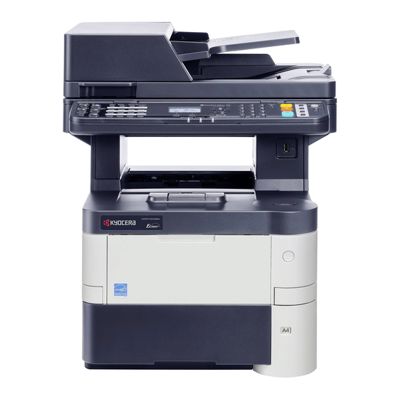
2NM/2NX/2NY/2NZ/2P0/2P6-1 1-1-2 Parts names (1) Main part appearance Figure 1-1-1 1. Document Processor 11. USB Memory Slot 2. Original Width Guides 12. Front Cover Open Button 3. Original Tray 13. Slit Glass 4. Original Eject Table 14. Original Size Indicator Plates 5. - Page 22 2NM/2NX/2NY/2NZ/2P0/2P6 (2) A connector and an inside Figure 1-1-2 1. Option Interface Slot 8. MP Tray 2. Network Interface Connector 9. Paper Length Guide 3. USB Interface Connector 10. Paper Width Guide 4. Envelope Lever 11. Bottom Plate 5. Fuser Cover 12.
- Page 23 2NM/2NX/2NY/2NZ/2P0/2P6 Figure 1-1-3 14. Toner Container 15. Toner Container Lock Lever 16. Registration roller 17. Waste Toner Box 1-1-7...
- Page 24 2NM/2NX/2NY/2NZ/2P0/2P6 (3) Option Figure 1-1-4 1. Card Reader 5. Cassette 5 2. Cassette 2 6. Rear Tray 3. Cassette 3 7. Eject Paper Stopper 4. Cassette 4 1-1-8...
- Page 25 2NM/2NX/2NY/2NZ/2P0/2P6 (4) Operation panel (4-1) Basic model 25 24 Figure 1-1-5 1. LCD 17. Power Indication 2. Arrow key 18. Energy Saver key 3. OK key 19. Authentication/Logout key 4. Function Menu key 20. Status/Job Cancel key 5. Select key(Left) 21.
- Page 26 2NM/2NX/2NY/2NZ/2P0/2P6 (4-2) HyPAS model 3 4 5 Figure 1-1-6 1. Home Key 11. Quick No. Search key 2. Status/Job Cancel key 12. Enter key 3. Copy key 13. Energy Saver key 4. Send key 14. Reset key 5. FAX key 15.
- Page 27 2NM/2NX/2NY/2NZ/2P0/2P6 1-1-3 Machine cross section [ DP ] [ Main UNIT ] Original path Paper path Optical path Paper path (Option) Figure 1-1-7 1. Cassette paper feed section 9. Transfer/Separation section 2. MP tray paper feed section 10. Fuser and eject/feed shift section 3.
- Page 28 2NM/2NX/2NY/2NZ/2P0/2P6-1 1-1-4 Option composition The following optional equipment is available for the machine. (3) Card Authentication Kit (B) (1) PF-320 (5) SD Memory Card SDHC Memory Card (2) PT-320 (50/60 ppm model only) (4) Expansion Memory Software option (6) HD-6/HD-7 (7) IB-50 (8) IB-51 (9) Data Security Kit (E)
-
Page 29: Installation Environment
2NM/2NX/2NY/2NZ/2P0/2P6-1 1-2 Installation 1-2-1 Installation environment 1. Temperature: 10 to 32.5°C/50 to 90.5°F 2. Humidity: 15 to 80% RH 3. Power supply: 120 V AC, 12.0 A 220 - 240 V AC, 6.0 A 4. Power supply frequency: 50 Hz ±2%/60 Hz ±2% 5. -
Page 30: Unpacking And Installation
2NM/2NX/2NY/2NZ/2P0/2P6 1-2-2 Unpacking and installation (1) Installation procedure Start Unpacking Setting of the fuser pressure release lever Precaution for carrying the machine (40 ppm model only) Remove the tapes and spacer Connecting the power code Power on Install the paper feeder (option) Installing software Setup of a toner container Output an own-status report... - Page 31 2NM/2NX/2NY/2NZ/2P0/2P6-1 Unpacking Figure 1-2-2 1. Hinge joints 7. Power code 13. Plastic bag 2. Outer case 8. Operation guide etc. 14. Plastic bag 3. Upper front pad 9. Plastic bag 15. Lower left pad 4. Upper left pad 10. Document tray 16.
- Page 32 2NM/2NX/2NY/2NZ/2P0/2P6-1 Precaution for carrying the machine *: Be sure to hold the both side of the lower part of the machine by two persons when carrying it, as shown in the figure. *: Don't have the operation panel part, because there is fear of breakage. Figure 1-2-3 Remove the tapes and spacer *: Removed the packing components that a fixed tape and shock absorbing material etc.
- Page 33 2NM/2NX/2NY/2NZ/2P0/2P6 Setup of a toner container 1. Push the release button down and open the front cover. Release button Front cover Figure 1-2-5 Lock position Unlock position 2. Rotate the toner container lock lever to the lock position and then the unlock position.
- Page 34 2NM/2NX/2NY/2NZ/2P0/2P6 3. Remove the toner container from the main unit. Main unit Toner container Figure 1-2-7 *: Caution:Do not press too firmly on the center of the toner container or touch the toner feed slot or the terminal parts. Toner container Terminal part Toner feed slot Figure 1-2-8...
- Page 35 2NM/2NX/2NY/2NZ/2P0/2P6 4. Shake the turned toner container 10 times or more as shown in the figure in order to distribute the toner evenly inside the container. Figure 1-2-9 5. Set the toner container to the main unit Lock position and then turn the toner container lock lever to the lock position.
- Page 36 2NM/2NX/2NY/2NZ/2P0/2P6-1 Installing the waste toner box 1. Openthe controller cover. 2. Open the cap of the waste toner box. 3. Install the waste toner box. 4. Close the controller cover. Waste toner box Controller cover Figure 1-2-11 Connecting the cable Network [Connecting at Network] 1.
- Page 37 2NM/2NX/2NY/2NZ/2P0/2P6 Figure 1-2-12 Loading paper 1. Pull the cassette from the main unit out. Main unit Cassette Figure 1-2-13 *: Push the bottom plate down. (40 ppm model only) Cassette Botom plate Figure 1-2-14 Paper width guides 2. Push the lock lever on the right side guide and slide to the desired paper size.
- Page 38 2NM/2NX/2NY/2NZ/2P0/2P6 Paper length guide 3. Push the lock lever and slide the paper length guide to the desired paper size. 4. Turn the cassette size dial so that the size of the paper you are going to use appears in the cassette size window. Lock lever Cassette size dial Figure 1-2-16...
- Page 39 2NM/2NX/2NY/2NZ/2P0/2P6-1 Before loading paper When you open a new package of paper, fan the sheets to separate them slightly prior to loading in the following steps. (1)Bend the whole set of sheets to swell them in the middle. (2)Hold the stack at both ends and stretch it while keeping the entire stack swelled.
- Page 40 2NM/2NX/2NY/2NZ/2P0/2P6 Replace the operation panel sheet (except 240V AC model) 1. Slide the right operation lid and the left operation lid. 2. Remove the their lids. Right operation lid Left operation lid Figure 1-2-20 3. Remove the operation panel cover. 4.
- Page 41 2NM/2NX/2NY/2NZ/2P0/2P6 Setting of the fuser pressure release lever (40 ppm model only) 1. Open the rear cover. Release lever 2. Push the release lever down for (Shipment position) changing the lever position to a normal position from a shipment position. 3.
-
Page 42: Installing Software
2NM/2NX/2NY/2NZ/2P0/2P6 Power on 1. Turn the power switch on. Power switch Figure 1-2-24 *: At the first time when turning on the System Menu/Counter. 10:10 power switch, the machine runs Startup Machine Setup Wizard to set the following: 1. Date/Time 2. - Page 43 2NM/2NX/2NY/2NZ/2P0/2P6-1 Output an own-status report (maintenance item U000) *: For servise setup only 1. Enter the maintenance mode by entering 10871087 using the numeric keys. 2. Enter 000 using the numeric keys and press the start key. 3. Select Maintenance and press the start key to output a list of the current settings of the maintenance items.
- Page 44 2NM/2NX/2NY/2NZ/2P0/2P6 1-2-3 Installing an accessories option (1) Installing the SD card. Procedure 1. Open the rear cover. 2. Remove the upper interface cover and Upper the lower interface cover. interface cover Rear cover Lower interface cover Figure 1-2-26 3. Remove two screws and the Slot cover. Slot cover SD card slot 4.
- Page 45 2NM/2NX/2NY/2NZ/2P0/2P6 (2) Installing the expansion memory Procedure 1. Remove the controller cover. Controller cover Figure 1-2-28 2. Open the shield plate by rotating. Shield plate Figure 1-2-29 Memory socket 3. Insert the expansion memory into the memory socket so that the notches on the memory align with the correspond- ing protrusions in the slot.
- Page 46 2NM/2NX/2NY/2NZ/2P0/2P6 (3) Installing the HD-6/HD-7(SSD) Procedure 1. It checks that the indicator has disap- Indicator peared. 2. Turn the power switch off. 3. Unplug the power cord from the wall outlet. Wall outlet Power switch Power cord Figure 1-2-31 Upper 4.
- Page 47 2NM/2NX/2NY/2NZ/2P0/2P6 7. Insert the SSD in an option slot. 8. Fix the SSD with using two screws to main unit. Option slot Screws Figure 1-2-34 9. Refit two interface covers. 10. Close the rear cover. Rear cover Upper interface cover Lower interface cover Figure 1-2-35 11.
- Page 48 2NM/2NX/2NY/2NZ/2P0/2P6 (4) Installing the IC card reader holder (50/60 ppm model only) IC card reader holder installation requires the following parts): Parts Quantity Part.No. IC card reader holder 10 1702P6UN1 Supplied parts of IC card reader holder 10 (1702P6UN1): Parts Quantity Part.No.
- Page 49 2NM/2NX/2NY/2NZ/2P0/2P6 2. Route the USB cable from the IC card USB cable reader through the IC card reader holder ribs, wind around its back and route through another rib. IC card reder holder Figure 1-2-38 3. Slide the left operation lid and then Left Left operation remove it.
- Page 50 2NM/2NX/2NY/2NZ/2P0/2P6 6. Connect the USB connector to the USB Screw interface slot. 7. Fix the IC card reader holder using a IC card reader holder screw. 8. Refit all the removed parts. USB connector Operation panel assembly Figure 1-2-40 9. Affix a label on the ICcar reader cover aligning it with the positioning mark.
- Page 51 2NM/2NX/2NY/2NZ/2P0/2P6 Enabling IC Card Authentication Precautions To install the optional function, you need the License Key. Please access the designated website of your dealer or service representative, and register “Machine No.” indicated on your machine and “Product ID” indi- cated on the License Certificate supplied with the product to issue the License Key. 1.
- Page 52 2NM/2NX/2NY/2NZ/2P0/2P6 This page is intentionally left blank. 1-2-24...
- Page 53 2NM/2NX/2NY/2NZ/2P0/2P6 1-3 Maintenance Mode 1-3-1 Maintenance Mode The machine is equipped with a maintenance function which can be used to maintain and service the machine. (1) Executing a maintenance item Start Enter “10871087” using Maintenance mode is entered. the numeric keys. Enter the maintenance item number using the cursor up/down keys The maintenance item is selected.
- Page 54 2NM/2NX/2NY/2NZ/2P0/2P6 (2) Maintenance modes item list Item Section Content of maintenance item Summary General U000 Mainte Report It outputs to printing of each report, and USB. U001 Exit Mainte Maintenance mode is canceled. U002 Set Factory Def A factory-shipments setup (initialization) and packing mode are set up.
- Page 55 2NM/2NX/2NY/2NZ/2P0/2P6 Item Section Content of maintenance item Summary Operation U201 Init Touch Panel (HyPAS only) It adjusts, when the detection position of panel and the touch panel has shifted. support U203 Chk DP Ope Each simulation is operated with DP simple equipment substance.
- Page 56 2NM/2NX/2NY/2NZ/2P0/2P6 Item Section Content of maintenance item Summary U600 Init All Data According to the country code and the OEM code which were inputted, all the softswitches, backup data, and an image memory are initialized. U601 Init Keep Data Softswitches other than machine data are initialized according to the country code and the OEM code which were inputted.
- Page 57 2NM/2NX/2NY/2NZ/2P0/2P6 Item Section Content of maintenance item Summary U633 Comm Ctrl 4 It is whether communication by V.34 is per- mitted, and transmission and reception -- it sets up individually. It is set up whether 3429 Hz in V.34 symbol speed is used.
- Page 58 2NM/2NX/2NY/2NZ/2P0/2P6 Item Section Content of maintenance item Summary Others U901 Clr Paper FD Cnt The feed number of sheets count accord- ing to feed stage are displayed and cleared. U905 Option Cnt The each counter of DP and a sorter are displayed and cleared.
- Page 59 2NM/2NX/2NY/2NZ/2P0/2P6 (3) Contents of the maintenance mode items U000 Mainte Report Description Outputs lists of the current settings of the maintenance items and paper jam and service call occurrences. Outputs the event log. Also sends output data to the SD card. Purpose To check the current setting of the maintenance items, or paper jam or service call occurrences.
-
Page 60: Event Log
2NM/2NX/2NY/2NZ/2P0/2P6 [Event log] Event Log 2013/02/19 15:15 ECOSYS M3550idn Firmware version 2NM_2000.000.000 2013.02.19 [XXXXXXXX] [XXXXXXXX] [XXXXXXXX] (11) Paper Jam Log Counter Log Count. Event Descriprions Date and Time J0000: J4209: 5555555 0501.01.08.01.00 2013/02/12 17:30 J0100: J4211: 4444444 4002.01.08.01.00 2013/02/12 17:30 J0101: J4212: 3333333... - Page 61 2NM/2NX/2NY/2NZ/2P0/2P6 [Detail of event log] Items Description System version System date Engine software version Engine boot software version Operation panel software version Machine serial number Paper Jam Count. Event Remembers 1 to 16 of The total page count at the Log code (hexadecimal, 5 occurrence.
- Page 62 2NM/2NX/2NY/2NZ/2P0/2P6-2 Items Description Paper Jam (d) Detail of paper type (Hexadecimal) cont. 01: Plain 0A: Color 15: Custom 1 02: Transparency 0B: Prepunched 16: Custom 2 03: Preprinted 0C: Envelope 17: Custom 3 04: Labels 0D: Cardstock 18: Custom 4 05: Bond 0E: Coated 19: Custom 5...
- Page 63 2NM/2NX/2NY/2NZ/2P0/2P6-2 Items Description (10) Unknown Count. item Toner Log Remembers 1 to 5 of The total page count at the Unknown toner log code occurrence of unknown time of the toner empty (1 byte, 2 categories) toner detection. If the error with using an occurrence of the previous unknown toner container.
-
Page 64: Service Status Page
2NM/2NX/2NY/2NZ/2P0/2P6 [Service status page] Service Status Page 2013/02/19 15:15 Firmware version 2NM_2000.000.000 2013.02.19 [XXXXXXXX] [XXXXXXXX] [XXXXXXXX] Controller Information FAX Information Memory status (29) Rings (Normal) Total Size 2.0 GB (30) Rings (FAX/TEL) (31) Rings (TAD) Time (32) Option DIMM Size 16 MB Local Time Zone +01:00 Amsterdam... -
Page 65: Engine Information
2NM/2NX/2NY/2NZ/2P0/2P6 Service Status Page 2013/02/19 15:15 Firmware version 2NM_2000.000.000 2013.02.19 [XXXXXXXX] [XXXXXXXX] [XXXXXXXX] Engine Information Send Information (38) (42) NVRAM Version _1F31225_1F31225 Date and Time 2013/02/19 15:30 (39) (43) Scanner Version 2NM_1200.001.089 Address mail@bjd.ne.jp (40) FAX Slot1 FAX BOOT Version 2NM_5000.001.001 FAX APL Version 2NM_5100.001.001... - Page 66 2NM/2NX/2NY/2NZ/2P0/2P6 [Detail of service status page] Description Supplement Firmware version System date Engine soft version Engine boot version Operation panel mask version Machine serial number Standard memory size Local time zone Report output date Day/Month/Year hour:minute (10) NTP server name (11) Presence or absence of the optional Installed/Not Installed...
- Page 67 2NM/2NX/2NY/2NZ/2P0/2P6 Description Supplement (29) Number of rings 0 to 15 (30) Number of rings before automatic 0 to 15 switching (31) Number of rings before connecting to 0 to 15 answering machine (32) Optional DIMM size (33) FRPO setting (34) RP code Code the engine software version and the date of update.
- Page 68 2NM/2NX/2NY/2NZ/2P0/2P6-1 Description Supplement (49) Panel lock information 0: OFF/1: Partial lock/2: Full lock (50) USB information U00: Not installed/U01: Full speed/U02: Hi speed (51) Paper handling information 0: Paper source unit select/1: Paper source unit (52) Black and white printing double count 0: All single counts mode 1: A3, Single count, Less than 420 mm (length)
- Page 69 2NM/2NX/2NY/2NZ/2P0/2P6-1 Description Supplement FAX Board (Port1)/FAX Board (Port2)/FAX Memory/ (75) Data Sanitization information Main Memory/Panel Memory/Performed time 1: Success 0: Failure - : Not performed or Not installed (76) Toner low setting 0: Enabled 1: Disabled (77) Toner low detection level 0 to 100 (%) 1 to 65535 (78)
- Page 70 2NM/2NX/2NY/2NZ/2P0/2P6 U001 Exit Mainte Description Exits the maintenance mode and returns to the normal copy mode. Purpose To exit the maintenance mode. Method 1. Press the start key. The normal copy mode is entered. U002 Set Factory Def Description Restores the machine conditions to the factory default settings. Purpose To move the mirror frame of the scanner to the position for transport.
- Page 71 2NM/2NX/2NY/2NZ/2P0/2P6 U004 Machine No. Description Sets or displays the machine number. Purpose To check or set the machine number. Method Press the start key. If the machine serial number of engine PWB matches with that of main PWB. Display Description Machine No.
- Page 72 2NM/2NX/2NY/2NZ/2P0/2P6 U010 Set Mainte ID Description Sets the maintenance mode ID. Purpose Modify maintenance mode ID for more security. Method 1. Press the start key. 2. Select [Change] or [Initialize]. Display Description Change Changes the maintenance mode ID at the market. Initialize Initializes the maintenance mode ID at the market.
- Page 73 2NM/2NX/2NY/2NZ/2P0/2P6 U019 Firm Version Description Displays the part number of the ROM fitted to each board. Purpose To check the part number or to decide, if the newest version of ROM is installed. Method 1. Press the start key. The ROM version are displayed. 2.
- Page 74 2NM/2NX/2NY/2NZ/2P0/2P6 U021 Init memory Description Initializes all settings, except those pertinent to the type of machine, namely each counter, service call history and mode setting. Also initializes backup RAM according to region specification selected in maintenance item U252 Setting the destination. Purpose To return the machine settings to their factory default.
- Page 75 2NM/2NX/2NY/2NZ/2P0/2P6 U025 Firm Update(S) Description Used to execute FW-Update from the USB flash device while Very High is selected in the Security Level settings under the System Menu. Purpose Firmware upgrading is initiated by a service person to conduct U025 while a USB flash device is inserted.
- Page 76 2NM/2NX/2NY/2NZ/2P0/2P6 U034 Adj Paper Timing Description Adjusts the leading edge registration or center line. Purpose Make the adjustment if there is a regular error between the leading edges of the copy image and original. Make the adjustment if there is a regular error between the center lines of the copy image and original.
- Page 77 2NM/2NX/2NY/2NZ/2P0/2P6 5. Change the setting value using the cursor right/left keys or numeric keys. For output example 1, increase the value. For output example 2, decrease the value Leading edge registration (20 ± 1.0 mm) Correct image Output Output example 1 example 2 Figure 1-3-4 6.
- Page 78 2NM/2NX/2NY/2NZ/2P0/2P6 5. Change the setting value using the cursor right/left keys or numeric keys. For output example 1, increase the value. For output example 2, decrease the value. Center line of printing (within ± 2.0 mm) Correct image Output Output example 1 example 2 6.
- Page 79 2NM/2NX/2NY/2NZ/2P0/2P6 U065 Adj Scn Description Adjusts the magnification of the original scanning. Purpose Make the adjustment if the magnification in the main scanning direction is incorrect. Make the adjustment if the magnification in the auxiliary scanning direction is incorrect. Caution The magnification adjustment along the main scanning direction could cause black streaks depending on the content of the original document.
- Page 80 2NM/2NX/2NY/2NZ/2P0/2P6 Adjustment: Sub Scan 1. Change the setting value using the cursor right/left keys or numeric keys. For copy example 1, increase the value. For copy example 2, decrease the value. Increasing the value makes the image longer, while decreasing the value makes the image shorter.
- Page 81 2NM/2NX/2NY/2NZ/2P0/2P6 U066 Table Timing Description Adjusts the scanner leading edge registration of the original scanning. Purpose Make the adjustment if there is a regular error between the leading edges of the copy image and original. Adjustment 1. Press the start key. 2.
- Page 82 2NM/2NX/2NY/2NZ/2P0/2P6 U067 Table Center Description Adjusts the scanner center line of the original scanning. Purpose Make the adjustment if there is a regular error between the center lines of the copy image and original. Adjustment 1. Press the start key. 2.
- Page 83 2NM/2NX/2NY/2NZ/2P0/2P6 U068 DP Scn Start Pos Description Adjusts the position for scanning originals from the DP. Performs the test copy at the four scanning positions after adjusting. Purpose Used when the image fogging occurs because the scanning position is not proper when the DP is used.
- Page 84 2NM/2NX/2NY/2NZ/2P0/2P6-1 U070 Adj DP Motor Description Adjusts the DP original scanning speed. Purpose Make the adjustment if the magnification is incorrect in the auxiliary scanning direction when the DP is used. Adjustment 1. Press the start key. 2. Press the system menu key. 3.
- Page 85 2NM/2NX/2NY/2NZ/2P0/2P6 U071 DP Timing Description Adjusts the DP original scanning timing. Purpose Make the adjustment if there is a regular error between the leading or trailing edges of the original and the copy image when the DP is used. Method 1.
- Page 86 2NM/2NX/2NY/2NZ/2P0/2P6 Adjustment: Trailing edge registration 1. Change the setting value using the cursor right/left keys or numeric keys. For copy example 1, increase the value. For copy example 2, decrease the value. Original Copy Copy example 1 example 2 Figure 1-3-11 2.
- Page 87 2NM/2NX/2NY/2NZ/2P0/2P6 U072 DP Center Description Adjusts the scanning start position for the DP original. Purpose Make the adjustment if there is a regular error between the centers of the original and the copy image when the DP is used. Adjustment 1.
- Page 88 2NM/2NX/2NY/2NZ/2P0/2P6 U130 Set Toner Install Description To set ON/OFF of the toner installation mode. Purpose Toner installation is performed at the time of a machine setup. Setting 1. Press the start key. 2. Select [Mode]. 3. Set at On or Off. 4.
- Page 89 2NM/2NX/2NY/2NZ/2P0/2P6 U147 Set Toner Apply Description A mode setup of the operation which removes the toner in the development unit which carried out the charge rise is performed. Purpose The basic target does not need to change a setup. However, the mode is changed when outputting a manuscript with an always low printing rate in large quantities.
- Page 90 2NM/2NX/2NY/2NZ/2P0/2P6-1 U201 Init Touch Panel (HyPAS only) Description Adjust touch panel detecting positions. Purpose When the panel PWB or the operation panel is replaced or if the detecting positions are not aligned, perform this simulation to correct and confirm. Method 1.
- Page 91 2NM/2NX/2NY/2NZ/2P0/2P6 U203 Chk DP Ope Description Simulates the original conveying operation separately in the DP. Purpose To check the DP operation. Method 1. Press the start key. 2. Place an original in the DP if running this simulation with paper. 3.
-
Page 92: Display Description
2NM/2NX/2NY/2NZ/2P0/2P6-1 U207 Chk Panel Key Description Checks operation of the operation panel keys. Purpose To check operation of all the keys on the operation panel. Method 1. Press the start key. The screen for executing is displayed. 2. [Count0] is displayed and the left most LED on the operation panel lights. Display Description Keypress counter. - Page 93 2NM/2NX/2NY/2NZ/2P0/2P6 U222 Set IC Card Type Setting the IC card type Description Sets the type of IC card. Purpose To change the type of IC card. Setting 1. Press the start key. 2. Select the item. Display Description Other The type of IC card is not SSFC SSFC The type of IC card is SSFC * : Initial setting: Other...
- Page 94 2NM/2NX/2NY/2NZ/2P0/2P6 U250 Mnt Cnt Pre-set Description Changes preset values for maintenance cycle. Purpose Provides changing the time when the message to acknowledge to conduct maintenance adjust- ment is periodically displayed. Setting 1. Press the start key. 2. Select the item to be set. 3.
- Page 95 2NM/2NX/2NY/2NZ/2P0/2P6 U251 Clr Mnt Cnt Description Displays and clears or changes the maintenance count. Purpose To verify the maintenance counter count. Also to clear the count during maintenance service. Setting 1. Press the start key. 2. Select the item to be changed. 3.
- Page 96 2NM/2NX/2NY/2NZ/2P0/2P6-1 U252 Set Dest Description Switches the operations and screens of the machine according to the destination. Purpose To be executed after initializing the backup RAM, in order to return the setting to the value before replacement or initialization. Method 1.
- Page 97 2NM/2NX/2NY/2NZ/2P0/2P6 U253 Sel D/S Count Description Switches the count system for the total counter and other counters. Purpose Used to select, according to the preference of the user (copy service provider), if folio size paper is to be counted as one sheet (single count) or two sheets (double count). Setting 1.
- Page 98 2NM/2NX/2NY/2NZ/2P0/2P6 U265 Set Model Dest Description Sets the OEM purchaser code. Purpose Sets the code when replacing the main board and the like. Setting 1. Press the start key. 2. Change the setting using the +- keys or numeric keys. Display Description Sets the OEM purchaser code.
- Page 99 2NM/2NX/2NY/2NZ/2P0/2P6 U332 Adj Calc Rate Description Sets the coefficient of nonstandard sizes in relation to the A4/Letter size. The coefficient set here is used to convert the black ratio in relation to the A4/Letter size and to display the result in user simulation.
- Page 100 2NM/2NX/2NY/2NZ/2P0/2P6 U339 Chk Drum Heater Description The change of a system menu display of a drum heater setup is set up. Purpose A setup of a drum heater is performed at the time of the change of a display on a system menu. 1.
- Page 101 2NM/2NX/2NY/2NZ/2P0/2P6 U345 Set Mnt Time Disp Description Sets when to display a message notifying that the time for maintenance is about to be reached,by setting the number of copies that can be made before the current maintenance cycle ends. When the difference between the number of copies of the maintenance cycle and that of the main- tenance count reaches the set value, the message is displayed.
- Page 102 2NM/2NX/2NY/2NZ/2P0/2P6 U346 Slct Sleep Mode Description A sleep mode-related setting change is performed. Purpose It uses in order to perform a sleep mode-related setting change. Method 1. Press the start key. 2. Select the item tobe set. Display Description Timer/Sleep Level BAM conformity country setup Auto sleep An On/Off setup of an AutoSleep function...
- Page 103 2NM/2NX/2NY/2NZ/2P0/2P6 U402 Adjust Margin Description Adjusts margins for image printing. Purpose Make the adjustment if margins are incorrect. Adjustment 1. Press the start key. 2. Press the system menu key. 3. Press the start key to output a test pattern. 4.
- Page 104 2NM/2NX/2NY/2NZ/2P0/2P6 U403 Scan Margin Tbl Description Adjusts margins for scanning the original on the contact glass. Purpose Make the adjustment if margins are incorrect. Adjustment 1. Press the start key. 2. Press the system menu key. 3. Place an original and press the start key to make a test copy. 4.
- Page 105 2NM/2NX/2NY/2NZ/2P0/2P6 U404 Scan Margin DP Description Adjusts margins for scanning the original from the DP. Purpose Make the adjustment if margins are incorrect. Adjustment 1. Press the start key. 2. Press the system menu key. 3. Place an original on the DP and press the start key to make a test copy. 4.
- Page 106 2NM/2NX/2NY/2NZ/2P0/2P6-1 U411 Auto Adj Scn Description Uses a specified original and automatically adjusts the following items in the scanner and the DP scanning sections. Scanner section: Original size magnification, leading edge timing, center line, input gamma, input gamma in monochrome mode and matrix. DP scanning section: Original size magnification, leading edge timing, center line.
- Page 107 2NM/2NX/2NY/2NZ/2P0/2P6-1 Method: Table To Automaticary enter the target value : Usually, it adjusts here. 1. Set a specified original (P/N: 302NM94340) on the platen. 2. Enter maintenance item U411. 3. Select [Target]. 4. Select [Auto] and press the start key. 5.
- Page 108 2NM/2NX/2NY/2NZ/2P0/2P6-1 Codes Description Corrective Action Black band is not detected (DP main scan- 1. Check the attachment position of ning direction far end) 2. Check a lighting of the lamp or Black band is not detected (DP main scan- replace. ning direction near end) 3.
- Page 109 2NM/2NX/2NY/2NZ/2P0/2P6-1 Codes Description Corrective Action Lab value searching error Check the following and perform again. - Isn't the bar code dirty? - Is the position of a original right? - Is a bar code position right? Lab value comparing error Check the following and perform again.
- Page 110 2NM/2NX/2NY/2NZ/2P0/2P6-1 U425 Set Target Description Enters the lab values that is indicated on the back of the chart (P/N: 302NM94340) used for adjustment. Purpose Performs data input in order to correct for differences in originals during automatic adjustment. Method 1. Press the start key. 2.
- Page 111 2NM/2NX/2NY/2NZ/2P0/2P6-1 Setting: [Adjust Original] *: This setting is usually unnecessary. Display Description Setting range Initial setting Dist1 Sets the adjustment value of a leading 4.0 to 6.0 edge. Dist2 Sets the adjustment value of a left edge. 9.0 to 11.0 10.0 Dist3 Sets the adjustment value of a trailing...
- Page 112 2NM/2NX/2NY/2NZ/2P0/2P6-1 Setting: [DP] *: This setting is usually unnecessary. Display Description Setting range Initial setting Lead A value of length of detecting the leading 14.0 to 16.0 15.0 edge. Main Scan A value of width of main scan. 14.0 to 16.0 15.0 Sub Scan A value of length of sub scan.
- Page 113 2NM/2NX/2NY/2NZ/2P0/2P6 U520 Set TDRS Description Perform TDRS settings and information views. Purpose Perform TDRS settings and information views. Method 1. Press the start key. 2. Select the item. Display Description Registration Transition to the TDRS Manager registering dialog Information Transition to the Device Agent description dialog On/Off Config Transition to the TDRS features dialog Setting: [Registration]...
- Page 114 2NM/2NX/2NY/2NZ/2P0/2P6-1 Error Codes Codes Description Codes Description e0001 t0001 HDD is unavailable. Fatal error. e0002 t0002 USB memory is unavailable. Error in processing the network. e0003 The file to import does not exist t0003 An illegal parameter error. in the USB. e0004 t0004 Reading from the USB has...
- Page 115 2NM/2NX/2NY/2NZ/2P0/2P6-1 U600 Init All Data Description Initializes software switches and all data in the backup data on the FAX control board, according to the destination and OEM. Executes the check of the file system, when abnormality of the file system is detected, initializes the file system, communication past record and register setting contents.
- Page 116 2NM/2NX/2NY/2NZ/2P0/2P6 Code Destination Code Destination Russia Austria CTR21 (European nations) ↑ Switzerland ↑ Italy ↑ Belgium ↑ Germany ↑ Denmark ↑ Spain ↑ Finland ↑ U.K. ↑ Portugal ↑ Netherlands ↑ Ireland ↑ Sweden ↑ Norway ↑ France Taiwan 1-3-64...
- Page 117 2NM/2NX/2NY/2NZ/2P0/2P6-1 U601 Init Keep Data Description Initializes software switches on the FAX control board according to the destination and OEM. Purpose To initialize the FAX control board without changing user registration data. 1. Press the start key. The screen for entering the destination code and OEM code is displayed. 2.
- Page 118 2NM/2NX/2NY/2NZ/2P0/2P6 U603 User Data 1 Description Makes user settings to enable the use of the machine as a fax. Purpose To be executed as required. Method 1. Press the start key. 2. Select [Line Type] and press the start key. Display Description Line Type...
- Page 119 2NM/2NX/2NY/2NZ/2P0/2P6 U604 User Data 2 Description Makes user settings to enable the use of the machine as a fax. Purpose Use this if the user wishes to adjust the number of rings that occur before the unit switches into fax receiving mode when fax/telephone auto-select is enabled.
- Page 120 2NM/2NX/2NY/2NZ/2P0/2P6 U610 System Setting 1 Description Makes settings for fax reception regarding the sizes of the fax paper and received images and automatic printing of the protocol list. Method 1. Press the start key. 2. Select the item to be set. Display Description Cut Line:A4...
- Page 121 2NM/2NX/2NY/2NZ/2P0/2P6 Setting the number of lines to be ignored when receiving a fax in the auto reduction mode Sets the maximum number of lines to be ignored if the received data volume exceeds the record- ing capacity when the data is recorded in the auto reduction mode. If the number of excess lines is below the setting, those lines are ignored.
- Page 122 2NM/2NX/2NY/2NZ/2P0/2P6 U611 System Setting 2 Description Sets the number of adjustment lines for automatic reduction. Purpose It carries out to set up the number of adjustment lines of automatic reduction. Method 1. Press the start key. 2. Select the item to be set. Display Description ADJ LINES...
- Page 123 2NM/2NX/2NY/2NZ/2P0/2P6 U612 System Setting 3 Description Makes settings for fax transmission regarding operation and automatic printing of the protocol list. Method 1. Press the start key. 2. Select the item to be set. Display Description Auto Reduct Selects if auto reduction in the auxiliary direction is to be performed. Protocol List Sets the automatic printing of the protocol list.
- Page 124 2NM/2NX/2NY/2NZ/2P0/2P6 U620 FAX System Description Sets the signal detection method for remote switching. Be sure to change the setting according to the type of telephone connected to the machine. Purpose The decision system of a remote change is set up to compensate for a user's telephone classifica- tion, peculiarity.
- Page 125 2NM/2NX/2NY/2NZ/2P0/2P6 U625 Set Comm Description Makes settings for the auto redialing interval and the number of times of auto redialing. Purpose Change the setting to prevent the following problems: fax transmission is not possible due to too short redial interval, or fax transmission takes too much time to complete due to too long redial interval.
- Page 126 2NM/2NX/2NY/2NZ/2P0/2P6 U630 Comm Ctrl 1 Description Makes settings for fax transmission regarding the communication. Purpose The event of a request for user. Reduce transmission time and the reception of accuracy when using poor quality line. Improve the accuracy of communication at international communication. Method 1.
- Page 127 2NM/2NX/2NY/2NZ/2P0/2P6 Setting the waiting period to prevent echo problems at the sender Sets the period before a DCS signal is sent after a DIS signal is received. Used when problems occur due to echoes at the sender. 1. Select the setting. Display Description Sends a DCS 500 ms after receiving a DIS.
- Page 128 2NM/2NX/2NY/2NZ/2P0/2P6 U631 Comm Ctrl 2 Description Makes settings regarding fax transmission. Purpose Transmission and reception of ECM are set up. The frequency of CED is set up. 1. Press the start key. 2. Select the item to be set. Display Description ECM TX Sets ECM transmission.
- Page 129 2NM/2NX/2NY/2NZ/2P0/2P6 Setting: Freq. Sets the frequency of the CED signal. Used as one of the measures to improve transmission per- formance for international communications. 1. Select the setting. Display Description 2100 2100Hz 1100 1100Hz * : Initial setting: 2100 2. Press the start key. The setting is set. Completion Press the stop key.
- Page 130 2NM/2NX/2NY/2NZ/2P0/2P6 U632 Comm Ctrl 3 Description Makes settings for fax transmission regarding the communication. Purpose Reduction of error communication when a low quality circuit is used. When changing a FAX/TEL automatic change. Method 1. Press the start key. 2. Select the item to be set. Display Description DIS 4Byte...
- Page 131 2NM/2NX/2NY/2NZ/2P0/2P6 U633 Comm Ctrl 4 Description Makes settings for fax transmission regarding the communication. Purpose To reduce transmission errors when a low quality line is used. Method 1. Press the start key. 2. Select the item to be set. Display Description V.34 Enables or disables V.34 communication.
- Page 132 2NM/2NX/2NY/2NZ/2P0/2P6 Setting the number of times of DIS signal reception Sets the number of times to receive the DIS signal to once or twice. Used as one of the correction measures for transmission errors and other problems. 1. Select the setting. Display Description Once...
- Page 133 2NM/2NX/2NY/2NZ/2P0/2P6 U634 Comm Ctrl 5 Description Sets the maximum number of error bytes judged acceptable when receiving a TCF signal. Used as a measure to ease transmission conditions if transmission errors occur. Purpose Do to alleviate the communication conditions. Setting 1.
- Page 134 2NM/2NX/2NY/2NZ/2P0/2P6 U640 Comm Time 1 Description Sets the detection time when one-shot detection is selected for remote switching. (This setting item will be displayed, but the setting made is ineffective.) Sets the detection time when continuous detection is selected for remote switching. (This setting item will be displayed, but the setting made is ineffective.) Purpose The decision system of a remote change is set up to compensate for a user's telephone classifica-...
- Page 135 2NM/2NX/2NY/2NZ/2P0/2P6 U641 Comm Time 2 Description Sets the time-out time for fax transmission. Purpose To improve transmission performance for international communications mainly. Method 1. Press the start key. 2. Select the item to be set. Display Description T0 TIME OUT Sets the T0 time-out time.
- Page 136 2NM/2NX/2NY/2NZ/2P0/2P6 Setting: T2 time out The T2 time-out time decides the following. From CFR signal output to image data reception From image data reception to the next signal reception In ECM, from RNR signal detection to the next signal reception 1.
- Page 137 2NM/2NX/2NY/2NZ/2P0/2P6 Setting: Tb2 time out In the fax/telephone auto select mode, sets the time to start ringing an operator through the con- nected telephone after receiving a call as a fax machine (see figure 1-3-18). In the fax/telephone auto select mode, change the setting when fax reception is unsuccessful or a telephone fails to receive a call.
- Page 138 2NM/2NX/2NY/2NZ/2P0/2P6 U650 Modem 1 Description Sets the G3 cable equalizer. Sets the modem detection level. Purpose Perform the following adjustment to make the equalizer compatible with the line characteristics. To improve the transmission performance when a low quality line is used. Method 1.
- Page 139 2NM/2NX/2NY/2NZ/2P0/2P6 U651 Modem 2 Description Sets the modem output level. Sets the DTMF output level of a push-button dial telephone. Purpose Used if problems occur when sending a signal with a push-button dial telephone. Setting 1. Press the start key. 2.
- Page 140 2NM/2NX/2NY/2NZ/2P0/2P6 U660 Set Calls Description Makes setting regarding the network control unit (NCU). Purpose To be executed as required. Method 1. Press the start key. 2. Select the item to be set. Display Description Exchange Sets the connection to PBX/PSTN. Dial Tone Sets PSTN dial tone detection.
- Page 141 2NM/2NX/2NY/2NZ/2P0/2P6 Setting: Busy tone When a fax signal is sent, sets whether the line is disconnected immediately after a busy tone is detected, or the busy tone is not detected and the line remains connected until T0 time-out time. Fax transmission may fail due to incorrect busy tone detection. When set to 2, this problem may be prevented.
- Page 142 2NM/2NX/2NY/2NZ/2P0/2P6 U670 Output List Description Outputs a list of data regarding fax transmissions. Printing a list is disabled either when a job is remaining in the buffer or when [Pause All Print Jobs] is pressed to halt printing. Purpose To check conditions of use, settings and transmission procedures of the fax. Method 1.
- Page 143 2NM/2NX/2NY/2NZ/2P0/2P6 U695 Custom FAX Func Description Sets fax batch transmission ON/OFF. Also changes the print size priority at the time of small size reception. Purpose To be executed as required. Setting * : Select the setting. Display Description FAX Bulk TX fax batch transmission On/Off A5 Pt Pri Chg Change of print size priority at the time of small size reception...
- Page 144 2NM/2NX/2NY/2NZ/2P0/2P6 U699 Set Soft SW Description Sets the software switches on the FAX control board individually. Purpose To change the setting when a problem such as split output of received originals occurs. Since the communication performance is largely affected, normally this setting need not be changed.
- Page 145 2NM/2NX/2NY/2NZ/2P0/2P6 Description 0 2400bps/V34 3 FSK detection in V.8 4 4800 bps when low-speed setting is active 2 FIF length in transmission of more than 4 times of DIS/DTC signal <Communication time setting> Description 76543210 T3 timeout setting 76543210 T4 timeout setting (automatic equipment) 76543210 T5 timeout setting 76543210 Time before transmission of CNG (1100 Hz) signal 76543210 T0 timeout setting (manual equipment)
- Page 146 2NM/2NX/2NY/2NZ/2P0/2P6 Description 76543210 Allowable dial tone interruption time 76543210 Time for transmitting selection signal after closing the DC circuit 76543210 Ringer frequency detection invalid time 1-3-94...
- Page 147 2NM/2NX/2NY/2NZ/2P0/2P6 U901 Clr Paper FD Cnt Description Displays copy counts by paper feed locations. Purpose To check the time to replace consumable parts. Method 1. Press the start key. The counts by paper feed locations are displayed. Display Description MP tray Cass1 Cassette 1 Cass2...
- Page 148 2NM/2NX/2NY/2NZ/2P0/2P6 U905 Option Cnt Description Displays the counts of DP. Purpose To check the use of DP. Method 1. Press the start key. 2. Select [DP]. The count is displayed. Display Description Counts of DP Method: [DP] Display Description Counts of single-sided originals that has passed through the DP. RADP Counts of double-sided originals that has passed through the DP.
- Page 149 2NM/2NX/2NY/2NZ/2P0/2P6 U910 Clr Coverage Dat Description Clears the accumulated data for the print coverage per A4 size paper and its period of time (as shown on the service status report). Purpose To clear data as required at times such as during maintenance service. Method 1.
- Page 150 2NM/2NX/2NY/2NZ/2P0/2P6-1 U917 R/W Bkup Data Description Retrieves the backup data to a USB memory from the machine; or writes the data from the USB memory to the machine. Purpose Machine information is backed up and restored. Method 1. Press the power key on the operation panel, and after verifying the power indicator has gone off, switch off the main power switch.
- Page 151 2NM/2NX/2NY/2NZ/2P0/2P6 7. Select [On] using the cursor right/left keys. 8. Press the start key. Starts reading or writing. The progress of selected item is displayed in %. When an error occurs, the operation is canceled and an error code is displayed. 9.
- Page 152 2NM/2NX/2NY/2NZ/2P0/2P6 U920 Chg Cnt Description Checks the copy counts. Purpose To check the copy counts. Method 1. Press the start key. 2. Select the item to be set. Display Description Main Function Counts of main function Sub Function Counts of sub function [Setting: Main Function] 1.
- Page 153 2NM/2NX/2NY/2NZ/2P0/2P6 U927 Clr Chg/Life Cnt Description Resets all of the counts back to zero. Purpose The total account counter and the machine life counter can be cleared only once if all count values are 1000 or less. Method 1. Press the start key. 2.
- Page 154 2NM/2NX/2NY/2NZ/2P0/2P6 U969 Toner Area Code Description Displays the toner area code. Purpose To check the toner area code. Method 1. Press the start key. The toner area code is displayed. Display Description (Code) Toner area code is displayed. Completion Press the stop/clear key. The screen for selecting a maintenance item No. is displayed. U995 Mem Data Indi Description...
-
Page 155: Service Mode
2NM/2NX/2NY/2NZ/2P0/2P6 1-3-2 Service mode The machine is equipped with a maintenance function which can be used to maintain and service the machine. (1) Executing a service mode [Message Display] Ready to copy 1. Press the System Menu Key. System Menu: Quick Setup Wisard Language Report... - Page 156 2NM/2NX/2NY/2NZ/2P0/2P6 Service setting Description Display Page Test page The test page is printed with halftones. P.1-3-105 Developer Installs the toner to the developer unit. P.1-3-106 FAX Country Code Initializes software switches and all data. P.1-3-107 FAX Call Settings Sets FAX for connection. P.1-3-108 Alutitude Adjustment Sets the altitude adjustment mode.
- Page 157 2NM/2NX/2NY/2NZ/2P0/2P6 (2) Description of service mode Service items Description Test Page Printing a test page Description The halftones of sixteen different levels are printed for test. Purpose The developmental time of image error, the test print is performed for judgement of the engine-side or the scanner-side.
- Page 158 2NM/2NX/2NY/2NZ/2P0/2P6-1 Service items Description Initializing the developer unit (toner install mode) Developer Description The new developer unit is shipped from the factory with no toner contained. The devel- oper unit can be automatically replete with toner when a toner container is installed onto it and the printer is turned on.
- Page 159 2NM/2NX/2NY/2NZ/2P0/2P6-1 Service items Description FAX country FAX Country Code code Description Initializes software switches and all data in the backup data on the FAX control PWB, according to the destination. Purpose To initialize the FAX control PWB. Method 1. Enter the Service Setting menu. 2.
- Page 160 2NM/2NX/2NY/2NZ/2P0/2P6 Service items Description FAX call Setting FAX call setting Description Selects if a fax is to be connected to either a PBX or public switched telephone network. Selects the mode to connect an outside call when connected to a PBX. Access code registration for connection to PSTN.
- Page 161 2NM/2NX/2NY/2NZ/2P0/2P6-1 Service items Description Altitude adjust- Setting altitude adjustment ment Description Sets the altitude adjustment mode. Purpose Used when print quality deteriorates in an installation at the altitude of 1,500 meters or higher. Method 1. Enter the Service Setting menu. 2.
- Page 162 2NM/2NX/2NY/2NZ/2P0/2P6-1 Service items Description Memory Perform a memory diagnostic Diagnostics Description Diagnose memory at power up (whether reading and writing are executable). Purpose Execute memory check in purpose of rectifying a defective memory device which may possibly cause an unresolvable F call, locking, or abnormal images. Method 1.
-
Page 163: Paper Misfeed Detection
2NM/2NX/2NY/2NZ/2P0/2P6 1-4 Troubleshooting 1-4-1 Paper misfeed detection (1) Paper misfeed indication When a paper misfeed occurs, the machine immediately stops printing and displays the paper misfeed mes- sage on the operation panel. To remove paper misfed in the machine, pull out the cassette, open the paper conveying unit or paper conveying cover. - Page 164 2NM/2NX/2NY/2NZ/2P0/2P6 (2) Paper misfeed detection condition Machine + PF (Option) DPTS DPOS DPRS MPPS DUS2 DUS1 PS1/2 PFFS1 PFPS1 PFFS2 PFPS2 PFFS3 PFPS3 PFFS4 PFPS4 Figure 1-4-2 1-4-2...
- Page 165 2NM/2NX/2NY/2NZ/2P0/2P6 List of JAM Code Code Contents Conditions location* 0000 Initial jam The power is turned on when a sensor in the con- veying system is on. 0100 Secondary feeding timeout Secondary paper feed request given by the con- troller is unreachable. 0101 Wait for ready of print-process Process package won’t become ready.
- Page 166 2NM/2NX/2NY/2NZ/2P0/2P6 Code Contents Conditions location* 0511 Multiple sheets of jam The registration sensor 1 (RS1)*1 or registration sensor 3 (RS3)*2 does not turn off during paper feed from cassette 1. 0512 PF feed sensor 1 (PFFS1) does not turn off dur- ing paper feed from cassette 2.
- Page 167 2NM/2NX/2NY/2NZ/2P0/2P6 Code Contents Conditions location* 4002 Registration sensor 1 or 3 non The registration sensor 1 (RS1)*1 or registration arrival jam sensor 3 (RS3)*2 does not turn on during paper feed from cassette 2. 4003 The registration sensor 1 (RS1)*1 or registration sensor 3 (RS3)*2 does not turn on during paper feed from cassette 3.
- Page 168 2NM/2NX/2NY/2NZ/2P0/2P6 Code Contents Conditions location* 4111 Registration sensor 2 stay jam The registration sensor 2 (RS2) does not turn off during paper feed from cassette 1. 4112 The registration sensor 2 (RS2) does not turn off during paper feed from cassette 2. 4113 The registration sensor 2 (RS2) does not turn off during paper feed from cassette 3.
- Page 169 2NM/2NX/2NY/2NZ/2P0/2P6 Code Contents Conditions location* 4301 Duplex sensor 1 non arrival The duplex sensor 1 (DUS1) does not turn on during paper feed from cassette 1. 4302 The duplex sensor 1 (DUS1) does not turn on during paper feed from cassette 2. 4303 The duplex sensor 1 (DUS1) does not turn on during paper feed from cassette 3.
- Page 170 2NM/2NX/2NY/2NZ/2P0/2P6 Code Contents Conditions location* 9220 Initial jam of DP registration When DP reading is begun in the state where the sensor manuscript remains in the conveyance way *1: 40 ppm model only *2: 50/60 ppm model only *: Refer to figure 1-4-1 for paper misfeed indication (see page 1-4-1). 1-4-8...
- Page 171 2NM/2NX/2NY/2NZ/2P0/2P6 1-4-2 Troubleshooting (1) First check items If the paper is fed askew, jammed, curled, or leading-edge dog-eared, first perform to check the following items. Check items Check description Corrective measures Paper 1. Check the paper delivered is If a dog-ear has happened, check there are no objects dog-eared, skewed or existing in the conveying paths and, if any, fix.
- Page 172 2NM/2NX/2NY/2NZ/2P0/2P6 Check items Check description Corrective measures Settings/ 1. Check if the margin is If the check line is not situated at 20mm±1mm from the Detection 4.0±2.5mm from the leading leading edge, adjust the leading margin by U402. (see edge of paper. page 1-3-51) 2.
- Page 173 2NM/2NX/2NY/2NZ/2P0/2P6 Check items Check description Corrective measures Conveying 1. Check the conveying rollers Clean the conveying rollers or the pollyes. roller, feed have no paper dusts, toner, If variation in the external diameter or abrasion is roller or foreign objects observed, replace.
- Page 174 2NM/2NX/2NY/2NZ/2P0/2P6 (2) Items and corrective actions relating to the device that will cause paper jam Jam types Check description Corrective measures No-paper-feed jam or 1. Check if the jammed Replace the paper feed roller.(Service life of rubber the leading edge of paper or the printed roller is 300000 images *1) paper is curled back at...
- Page 175 2NM/2NX/2NY/2NZ/2P0/2P6 Jam types Check description Corrective measures Multiple-feed Jam 1. Check if the cutting If the cutting edge of the paper bundle is crumpled or (J0511, J0512, J0513, edge of the paper the cassette is loaded with multiple times of J0514, J0515, J0519) bundle is crumpled or replenishing paper, load new paper.
- Page 176 2NM/2NX/2NY/2NZ/2P0/2P6 Jam types Check description Corrective measures PF conveying sensor 1. Check to see if the If it won't operate without hinderance, re-assemble or stay jam actuator is operative replace the actuator's return spring. (J1413, J1414, J1415, without hinderance. J1614, J1615, J1815) 2.
- Page 177 2NM/2NX/2NY/2NZ/2P0/2P6 (3) Paper jam at feeding from cassette 1 Electrical parts that could cause paper jam during paper travelling at the primary feeding (to regist roller) Timing of detection Jam code J0501, J0511, J4101 *2, J4111 *2 Measures Related parts Registration sensor (RS) Control PWB (CONPWB) Paper feed clutch (PFCL)
- Page 178 2NM/2NX/2NY/2NZ/2P0/2P6 (4) Paper jam at feeding from cassette 2 (paper feerder) Electrical parts that could cause paper jam during paper travelling at the primary feeding ( to regist roller) Timing of detection Jam code J0502, J0512, J4002, J4012, J4102 2*, J4112 *2 Corrective Action Related parts PF main PWB (PF PWB)
- Page 179 2NM/2NX/2NY/2NZ/2P0/2P6 Checking procedure at the On/Off control signal output connector occurrence of Corrective action at the occurrence (terminal), point of checking connection J4002/J4012 J4102/J4112 *2 Paper feed clutch (PFCL): Operation C-RPWB YC12-4 check Main motor : Operation check C-RPWB YC10-1/2/3/4 Connect right PWB : Replace *2: 50/60 ppm model only (5) Paper jam at feeding from multi paper feed...
- Page 180 2NM/2NX/2NY/2NZ/2P0/2P6 (6) Paper jam at the duplex re-feeding part Electrical parts that could cause paper jam during paper travelling at the primary feeding ( to regist roller) Timing of detection Jam code J0508,J0518 Corrective Action Related parts Registration sensor (RS) Control PWB (CONPWB) Duplex clutch (DUCL) *2 Connect right PWB (C-RPWB)
- Page 181 2NM/2NX/2NY/2NZ/2P0/2P6 (7) Electrical parts that could cause paper jam at the transfer , the fuser and the eject parts Timing of detection Jam code J4201,J4211 Corrective Action Related parts Eject sensor (ES) Control PWB (CONPWB) Registration clutch (RCL) Connect right PWB (C-RPWB) Connect left PWB (C-LPWB) Main motor (MM) Eject motor (EM)
- Page 182 2NM/2NX/2NY/2NZ/2P0/2P6 1-4-3 Self-diagnostic function (1) Self-diagnostic function This machine is equipped with self-diagnostic function. When a problem is detected, the machine stops print- ing and display an error message on the operation panel. An error message consists of a message prompting a contact to service personnel and a four-digit error code indicating the type of the error.
- Page 183 2NM/2NX/2NY/2NZ/2P0/2P6 Check procedures/ Code Contents Related parts corrective measures 1. Turn the main power swtch off and after 0110 Backup memory data error EEPROM (Control PWB) 5 seconds, then turn power on. 2. Check that the EEPROM on the main circuit PWB is peroperly installed on the main circuit PWB and, if not, re-install it.
- Page 184 2NM/2NX/2NY/2NZ/2P0/2P6 Check procedures/ Code Contents Related parts corrective measures 1. Check that the EEPROMs installed in 0170 Billing counting error EEPROM The values on the main circuit the control PWB are correct and, if not, PWB and on the engine do use the correct EEPROM for the model.
- Page 185 2NM/2NX/2NY/2NZ/2P0/2P6 Check procedures/ Code Contents Related parts corrective measures FAX control PWB 1. Turn the main power swtch off and after 0870 PCFAX control PWB to main PWB high capacity data 5 seconds, re-mount the FAX controller transfer error PWB, then turn power on. High-capacity data transfer 2.
- Page 186 2NM/2NX/2NY/2NZ/2P0/2P6 Check procedures/ Code Contents Related parts corrective measures 1020 PF lift motor 1 error Bottom plate ele- Check to see if the bottom plate can move (paper feeder) vation mechanism smoothly and repair it if any problem is in the cassette found.
- Page 187 2NM/2NX/2NY/2NZ/2P0/2P6 Check procedures/ Code Contents Related parts corrective measures 1050 PF lift motor 4 error Bottom plate ele- Check to see if the bottom plate can move (paper feeder) vation mechanism smoothly and repair it if any problem is in the cassette found.
- Page 188 2NM/2NX/2NY/2NZ/2P0/2P6 Check procedures/ Code Contents Related parts corrective measures Paper feeder 1820 Paper feeder 3 communica- Check the wiring connection status with tion error paper feeder unit 2 and, if necessary, try A communication error from connecting it again. paper feeder is detected 10 PF main PWB 1.
- Page 189 2NM/2NX/2NY/2NZ/2P0/2P6 Check procedures/ Code Contents Related parts corrective measures 1. Confirm that the wiring connector is 1930 Paper feeder 4 EEPROM PF main PWB error (EEPROM) firmly connected and, if necessary, When writing the data, read connect the connector all the way in. and write data does not match 2.
- Page 190 2NM/2NX/2NY/2NZ/2P0/2P6 Check procedures/ Code Contents Related parts corrective measures 2200 Drum motor drive error Connector cable or Reinsert the connector. Also check for conti- (50/60 ppm model only) poor contact in the nuity within the connector cable. If none, connector replace the cable.
- Page 191 2NM/2NX/2NY/2NZ/2P0/2P6 Check procedures/ Code Contents Related parts corrective measures 2340 Envelope motor error Connector cable or Reinsert the connector. Also check for conti- (Timeout) poor contact in the nuity within the connector cable. If none, (50/60 ppm model only) connector replace the cable.
- Page 192 2NM/2NX/2NY/2NZ/2P0/2P6 Check procedures/ Code Contents Related parts corrective measures 2620 PF drive motor 3 error Connector cable or Reinsert the connector. Also check for conti- (paper feeder 3) poor contact in the nuity within the connector cable. If none, connector replace the cable.
- Page 193 2NM/2NX/2NY/2NZ/2P0/2P6 Check procedures/ Code Contents Related parts corrective measures Image scanner 3100 Scanner carriage error 1. Move the scanner by the hand to check The home position is not cor- motor whether it is unusually difficult to move. rect when the power is turned 2.
- Page 194 2NM/2NX/2NY/2NZ/2P0/2P6 Check procedures/ Code Contents Related parts corrective measures Polygon motor 1. Confirm that the wiring connector is 4000 Polygon motor steady-state error (LSU) firmly connected and, if necessary, After Polygon motor is stabi- connect the connector all the way in. lized, the ready signal is at the Laser scanner unit and control PWB H level for 20 s continuously.
- Page 195 2NM/2NX/2NY/2NZ/2P0/2P6 Check procedures/ Code Contents Related parts corrective measures Fuser unit 1. Check that no paper jam is present. 6000 Broken fuser heater wire (Center) 2. Confirm that the wiring connector is firmly connected and, if necessary, (50/60 ppm model) connect the connector all the way in.
- Page 196 2NM/2NX/2NY/2NZ/2P0/2P6 Check procedures/ Code Contents Related parts corrective measures Fuser unit 1. Confirm that the wiring connector is 6020 Abnormally high fuser thermistor 2 temperature firmly connected and, if necessary, (Center) connect the connector all the way in. (50/60 ppm model only) Fuser unit and fuser thermistor connect PWB (YC2) Fuser thermistor 2 detects a...
- Page 197 2NM/2NX/2NY/2NZ/2P0/2P6 Check procedures/ Code Contents Related parts corrective measures Fuser unit 1. Check that no paper jam is present. 6030 Broken fuser thermistor 2 wire (Center) 2. Confirm that the wiring connector is (50/60 ppm model only) firmly connected and, if necessary, connect the connector all the way in.
- Page 198 2NM/2NX/2NY/2NZ/2P0/2P6 Check procedures/ Code Contents Related parts corrective measures 6000/ Broken fuser heater wire Connector pin If the I/F connector pins of the fuser unit and 6020/ Abnormally high fuser the main unit are deformed owing to foreign thermistor 2 temperature matters, replace the connectors or the units 6030/ Broken fuser thermistor 2...
- Page 199 2NM/2NX/2NY/2NZ/2P0/2P6 Check procedures/ Code Contents Related parts corrective measures 6120 Abnormally high fuser Connector pin See page 1-4-36. thermistor 1 temperature Triac See page 1-4-36. Fuser thermistor Replace the fuser unit (see page 1-5-44). (50/60 ppm model) The detection temperature of Contrl PWB Replace the control PWB and check for cor- fuser thermistor 1 is higher...
- Page 200 2NM/2NX/2NY/2NZ/2P0/2P6 Check procedures/ Code Contents Related parts corrective measures Zero-cross signal error Fuser unit 1. Confirm that the wiring connector is 6400 While fuser heater ON/OFF firmly connected and, if necessary, control is performed, the zero- connect the connector all the way in. cross signal is not input within Power source PWB and connect right 2 s.
- Page 201 2NM/2NX/2NY/2NZ/2P0/2P6 Check procedures/ Code Contents Related parts corrective measures 1. Check the toner sensor output. 7100 Toner sensor error Toner sensor 2. Confirm that the wiring connector is Sensor output value of 930 or firmly connected and, if necessary, more continuously for 5 s. connect the connector all the way in.
- Page 202 2NM/2NX/2NY/2NZ/2P0/2P6 Check procedures/ Code Contents Related parts corrective measures 7400 Developer unit non-install- Connector cable or Reinsert the connector. Also check for conti- ing error poor contact in the nuity within the connector cable. If none, connector replace the cable. Sensor output value of 31 or Developer unit and drum PWB (YC3) less continuously for 5 s.
- Page 203 2NM/2NX/2NY/2NZ/2P0/2P6 Check procedures/ Code Contents Related parts corrective measures 1. Confirm that the wiring connector is 7810 Short-circuited tempera- Temperature ture sensor wire firmly connected and, if necessary, sensor connect the connector all the way in. Input from temperature sensor Temperature sensor and control PWB is 31 or less continuously for 5 (YC30)
- Page 204 2NM/2NX/2NY/2NZ/2P0/2P6 Check procedures/ Code Contents Related parts corrective measures F010 Control PWB checksum Control PWB Turn the main power switch off/on to restart error the machine. If the error is not resolved, replace control PWB and check for correct operation (see page 2-2-12). F020 Control PWB RAM check Main memory...
-
Page 205: Image Formation Problems
2NM/2NX/2NY/2NZ/2P0/2P6 1-4-4 Image formation problems Isolate the component an image defect has occurred from. <A guide to isolate the component of the cause.> Print a test page and check whether an image defect happens. (System Menu > Adjustment/Maintenance > Service setting) YES: Main unit as the cause of defect NO: Scanner as the cause of defect Perform enlarged or reduced copying and verify if the defective images are enlarged or reduced, accordingly. - Page 206 2NM/2NX/2NY/2NZ/2P0/2P6 1-4-5 Poor image (due to DP and scanner reading) (1) No image (2) No image (3) Image is too (4) The back- (5) White streaks appears appears light. ground is col- are printed ver- (entirely white). (entirely black). ored. tically.
- Page 207 2NM/2NX/2NY/2NZ/2P0/2P6 (1) No image appears (entirely white). Print example 1. Table scanning Defective part Check description Corrective Action Contact glass assy Check the location the contact Re-mount the contact glass if it is hanged off. glass is mounted. FFC cable CCD Reinsert the connector if it its connection is Check the FFC cable between loose.
- Page 208 2NM/2NX/2NY/2NZ/2P0/2P6 2. DP-scanning Defective part Check description Corrective Action Original document Verify the sides of the original If the sides of the original document are document. reversed, place the original document properly. Contact glass assy Check the location the contact Re-mount the contact glass if it is hanged off.
- Page 209 2NM/2NX/2NY/2NZ/2P0/2P6 (2) No image appears (entirely black). Print example 1. Table scanning Defective part Check description Corrective Action FFC cable CCD Check the FFC cable between Reinsert the connector if its connection is the CCD and control PWB is loose. Or, if conduction is lot, replace the wire. properly connected.
- Page 210 2NM/2NX/2NY/2NZ/2P0/2P6 (3) Image is too light. Print example 1. Table scanning Defective part Check description Corrective Action The settings of the Check the settings of the adjust- 1. Deactivate EcoPrint if it is activated. Or, if adjustment of den- ment of density. the density is too low, chosse an image sity quality that suits the original docuemt in...
- Page 211 2NM/2NX/2NY/2NZ/2P0/2P6 2. DP-scanning Defective part Check description Corrective Action The settings of the Check the settings of the adjust- 1. Deactivate EcoPrint if it is activated. Or, if adjustment of den- ment of density. the density is too low, chosse an image sity quality that suits the original docuemt in type.
- Page 212 2NM/2NX/2NY/2NZ/2P0/2P6 (4) The background is colored. Print example 1. Table scanning Defective part Check description Corrective Action Original document 1. Check if the background 1. If the background density of the original density of the original document is too dense, perform automatic document is too dense.
- Page 213 2NM/2NX/2NY/2NZ/2P0/2P6 2. DP-scanning Defective part Check description Corrective Action Original document 1. Check if the background 1. If the background density of the original density of the original document is too dense, perform automatic document is too dense. background adjustment.Or, adjust density 2.
- Page 214 2NM/2NX/2NY/2NZ/2P0/2P6 (5) White streaks are printed vertically. Print example 1. Table scanning Defective part Check description Corrective Action Original document Check whether the original If the original document is dirty, replace. document is dirty. Contact glass Check whether the contact glass If the contact glass is dirty, clean the contact is dirty.
- Page 215 2NM/2NX/2NY/2NZ/2P0/2P6 Defective part Check description Corrective Action Check whether the lens cover is Re-mount the lens cover if it is hanged off. hanged off. Shading plate Check whether the shading plate If the shading plate is dirty, perform is dirty. maintenance mode U063 to modify the shading position.
- Page 216 2NM/2NX/2NY/2NZ/2P0/2P6 (6) Black streaks appear longitudinally. Print example 1. Table scanning Defective part Check description Corrective Action Original document Check whether the original If the original document is dirty, replace. document is dirty. Original document Check if the size of the original If the size of the original document and its document and its reference size reference size do not match, set the correct...
- Page 217 2NM/2NX/2NY/2NZ/2P0/2P6 2. DP-scanning Defective part Check description Corrective Action Original document Check whether the original If the original document is dirty, replace. document is dirty. Original document Check if the size of the original If the size of the original document and its document and its reference size reference size do not match, set the correct match.
- Page 218 2NM/2NX/2NY/2NZ/2P0/2P6 (7) Streaks are printed horizontally. Print example 1. Table scanning Defective part Check description Corrective Action Original document Check whether the original If the original document is dirty, replace. document is dirty. Contact glass Check whether the contact glass If the contact glass is dirty, clean the contact is dirty.
- Page 219 2NM/2NX/2NY/2NZ/2P0/2P6 Defective part Check description Corrective Action Control PWB The control PWB is defective. Replace the control PWB.(see page 2-2-12) 1-4-57...
- Page 220 2NM/2NX/2NY/2NZ/2P0/2P6 (8) One side of the print image is darker or brighter than the other. Print example 1. Table scanning Defective part Check description Corrective Action Original document Check whether the original If the original document is dirty, replace. document is dirty. Original document Check if the original document If the original document has foldings or...
- Page 221 2NM/2NX/2NY/2NZ/2P0/2P6 Defective part Check description Corrective Action Contact glass Check whether the contact glass If the contact glass is dirty, clean the contact is dirty. glass, and the bottom part of the shading plate. Contact glass assy Check the location the contact Re-mount the contact glass if it is hanged off.
- Page 222 2NM/2NX/2NY/2NZ/2P0/2P6 (9) Black dots appear on the image. Print example 1. Table scanning Defective part Check description Corrective Action Original document Check whether the original If the original document is dirty, replace. document is dirty. Contact glass Check whether the contact glass If the contact glass is dirty, clean the contact is dirty.
- Page 223 2NM/2NX/2NY/2NZ/2P0/2P6 (10) Image is blurred. Print example 1. Table scanning Defective part Check description Corrective Action Rail Check that the carriage is If the carriage does not travel smoothly, smoothly operative. remove foreign objects on the front and back optical rails. Lamp unit Check that the carriage is If the carriage does not travel smoothly...
- Page 224 2NM/2NX/2NY/2NZ/2P0/2P6 Defective part Check description Corrective Action Scopper guide Check that the scopper guide is If the scopper guide does not rotate smoothly, smoothly operative. re-install. Conveying roller Check whether the conveying If the conveying roller is dirty, clean. (before and after roller is dirty.
- Page 225 2NM/2NX/2NY/2NZ/2P0/2P6 (11) The leading edge of the image is consistently misaligned with the original. Print example 1. Table scanning Defective part Check description Corrective Action Original document Check if the original document is If the original document is not properly placed loaded correctly on the contact on the contact glass, place it correctly.
- Page 226 2NM/2NX/2NY/2NZ/2P0/2P6 (12) Part of image is missing. Print example 1. Table scanning Defective part Check description Corrective Action Original document Check if the original document is If the original document is not properly placed loaded correctly on the contact on the contact glass, place it correctly. glass.
- Page 227 2NM/2NX/2NY/2NZ/2P0/2P6 Defective part Check description Corrective Action Original document 1. Check that the size of the 1. If the sizes of the original document and original document and the the paper size do not match, manually set paper size match on the the proper paper size for the original panel.
- Page 228 2NM/2NX/2NY/2NZ/2P0/2P6 (13) Image is out of focus. Print example 1. Table scanning Defective part Check description Corrective Action Original document Check whether the original If the original document is wavy, straighten.Or, document is wavy. replace the original document. Contact glass Check whether the contact glass If the contact glass is dew condensed, remove is dew condensed.
- Page 229 2NM/2NX/2NY/2NZ/2P0/2P6 Defective part Check description Corrective Action CCD sensor Check whether the CCD sensor If the CCD sensor glass is dew condensed, glass is dew condensed. remove the dew. Adjustment of the Check the automatic adjustment Perform maintenance mode U411, scanner of the scanner.
- Page 230 2NM/2NX/2NY/2NZ/2P0/2P6 (14) Image center does not align with the original center. Print example 1. Table scanning Defective part Check description Corrective Action Original document Check if the original document is If the original document is not properly placed loaded correctly on the contact on the contact glass, place it correctly.
- Page 231 2NM/2NX/2NY/2NZ/2P0/2P6 (15) Moires Print example 1. Table scanning Defective part Check description Corrective Action Settings of print Confirm whether the moire Switch print quality mode if the moire varies quality mode varies depending on print quality depending on print quality mode. mode.
- Page 232 2NM/2NX/2NY/2NZ/2P0/2P6 (16) Skewed image Print example 1. Table scanning Defective part Check description Corrective Action Original document Check if the original document is If the original document is not placed askew on fed askew. the contact glass, place it correctly. Adjustment of Check the scanner unit is quite If the scanner unit is not quite level, perform...
- Page 233 2NM/2NX/2NY/2NZ/2P0/2P6 (17) Abnormal image Print example 1. Table scanning Defective part Check description Corrective Action FFC cable CCD Check the FFC cable between Reinsert the connector if its connection is the CCD and control PWB is loose. Or, if conduction is lot, replace the wire. properly connected.
- Page 234 2NM/2NX/2NY/2NZ/2P0/2P6 1-4-6 Poor image (Image rendering problems: printer engine (1) No image (2) No image (3) Image is too (4) The back- (5) White streaks appears appears light. ground is col- are printed ver- (entirely white). (entirely black). ored. tically. See page1-4-74 See page1-4-75 See page1-4-76...
- Page 235 2NM/2NX/2NY/2NZ/2P0/2P6 (16) mage is blurred (18) The leading (19) Paper is wrin- (17)The leading (20)Fusing is loose. (Shifted edge of the edge of the kled. image is con- transferring). image is spo- sistently mis- radically mis- aligned with the aligned with original.
- Page 236 2NM/2NX/2NY/2NZ/2P0/2P6 (1) No image appears (entirely white). Print example Cause of trouble 1. No or defective developing bias output. 2. Failure of the rotation of the developing roller. 3. Defective transfer. 4. Laser is not dispersed from the laser scanner unit (LSU). 5.
- Page 237 2NM/2NX/2NY/2NZ/2P0/2P6 (2) No image appears (entirely black). Print example Cause of trouble 1. No main charging. 2. The laser from the LSU is activated simultaneously. Defective part Check description Corrective Action Charging roller Check whether the charging If the charging roller is not fixed properly, fix the roller is properly mounted.
- Page 238 2NM/2NX/2NY/2NZ/2P0/2P6 (3) Image is too light. Print example Cause of trouble 1. Variance in environments (dew formation). 2. Toner is under supplied, or deteriorated in quality.(Under charged) 3. The volatage of the developing bias is too low. 4. The volatage of the transfer current is too low. 5.
- Page 239 2NM/2NX/2NY/2NZ/2P0/2P6 Defective part Check description Corrective Action 1. The laser diode on the LSU Replace the LSU. (see page 1-5-25) APC PWB is out of control. 2. Check whether the internal mirrors are contaminated. Control PWB The control PWB is detective. Replace the control PWB.(see page 2-2-12) 1-4-77...
- Page 240 2NM/2NX/2NY/2NZ/2P0/2P6 (4) The background is colored. Print example Cause of trouble 1. Toner is deteriorated in quality (under-charged). 2. Toner is over-supplied. 3. Developing bias is too high. 4. The layer of toner is too thick on the developing roller (too much toner). 5.
- Page 241 2NM/2NX/2NY/2NZ/2P0/2P6 (5) White streaks are printed vertically. Print example Cause of trouble 1. Dirty LSU slit glass. 2. Foreign objects inside the developer unit. 3. Internal contamination 4. Dirty drum inside. Defective part Check description Corrective Action Developer unit Generate PGs by service mode. Replace the developer unit.
- Page 242 2NM/2NX/2NY/2NZ/2P0/2P6 (6) Black streaks appear longitudinally. Print example Cause of trouble 1. Dirty charging roller 2. Flawed or dirty drum unit 3. Damaged or paper dust bitten cleaning blade Defective part Check description Corrective Action Separation brush Check if the separation brush is If the separation brush is dirty, clean it using a dirty with paper dusts and waste brush.
- Page 243 2NM/2NX/2NY/2NZ/2P0/2P6 Defective part Check description Corrective Action Eject guide The Rib is contaminated with If it is duty,clean. toner. 1-4-81...
- Page 244 2NM/2NX/2NY/2NZ/2P0/2P6 (7) Black or white streaks appear horizontally. Print example Cause of trouble 1. Dirty developer unit or terminals 2. Flawed or dirty drum unit Improper grounding 3. Dirty transfer roller terminals Defective part Check description Corrective Action Developer unit 1.
- Page 245 2NM/2NX/2NY/2NZ/2P0/2P6-1 (8) Uneven density longitudinally. Print example Cause of trouble 1. Dirty LSU inside 2. The transfer roller is not pressed against the drum properly. 3. Drum condensation. Defective part Check description Corrective Action Transfer roller unit Check that the transfer roller unit 1.
- Page 246 2NM/2NX/2NY/2NZ/2P0/2P6 (9) Uneven density horizontally. Print example Cause of trouble 1. Defective laser scanner unit. 2. Improper charging roller rotation 3. Improper contact on the developer unit terminals Defective part Check description Corrective Action Check the emission of laser is Replace the LSU.
- Page 247 2NM/2NX/2NY/2NZ/2P0/2P6 (10) Black dots appear on the image. Print example Cause of trouble 1. Dirty charging roller 2. Flawed or dirty drum unit 3. Damaged or paper dust bitten cleaning blade Defective part Check description Corrective Action Drum unit Check the print image on paper If the drum has scratches, replace the drum has a problem at an interval unit.
- Page 248 2NM/2NX/2NY/2NZ/2P0/2P6 (11) Offset occurs. Print example Cause of trouble 1. Flawed or dirty drum unit 2. Developing bias leakage. Defective part Check description Corrective Action Paper 1. If the type of the paper being used falls Check that the type of the paper used falls within the range of outside the requirements, replace and use specifications.
- Page 249 2NM/2NX/2NY/2NZ/2P0/2P6 (12) Image is partly missing. Print example Cause of trouble 1. Flawed or dirty drum unit. 2. Deformed or dirty transfer roller on its surface. Defective part Check description Corrective Action Paper 1. If the paper is damp, replace.Choose a dry 1.
- Page 250 2NM/2NX/2NY/2NZ/2P0/2P6 (13) Image is out of focus. Print example Cause of trouble 1. Drum condensation. 2. Dirty LSU slit glass. Defective part Check description Corrective Action Paper 1. If the paper is damp, replace.Choose a dry 1. Check that the paper has moisture absorbed.
- Page 251 2NM/2NX/2NY/2NZ/2P0/2P6 (15) Unevenly repeating horizontal streaks in the printed objects. Spots in the printed objects. Print example Cause of trouble 1. Installation at a high altitude. 2. Using the paper with high surface resistance. Defective part Check description Corrective Action Developer unit The device is installed in an If the device is installed in an altitude greater...
- Page 252 2NM/2NX/2NY/2NZ/2P0/2P6 (16) mage is blurred (Shifted transferring). Print example Cause of trouble 1. The paper used does not conform to the requirement. 2. Imbalanced fuser unit pressures. Defective part Check description Corrective Action Paper 1. Check that the type of the 1.
- Page 253 2NM/2NX/2NY/2NZ/2P0/2P6 (17) The leading edge of the image is consistently misaligned with the original. Print example Cause of trouble 1. Improperly adjusted leading edge timing. 2. Improper amount of slack of the original document in front of the registration. Defective part Check description Corrective Action Regist roller...
- Page 254 2NM/2NX/2NY/2NZ/2P0/2P6 (18) The leading edge of the image is sporadically misaligned with the original. Print example Defective part Check description Corrective Action Paper feed clutch, Check that the clutches are 1. If it is not fixed properly, fix it properly. Registration clutch properly fit.IOr, check they are 2.
- Page 255 2NM/2NX/2NY/2NZ/2P0/2P6 (20) Fusing is loose. Print example Defective part Check description Corrective Action Paper 1. Check that the type of the 1. If the type of the paper being used falls paper used falls within the outside the requirements, replace and use range of specifications.
- Page 256 2NM/2NX/2NY/2NZ/2P0/2P6 (21) Image center does not align with the original center. Print example Defective part Check description Corrective Action Paper setting Check if paper is set correctly. Reload paper if the paper was not loaded correctly. Image position Perform adjustment if the value of U034 Center Excute U034 to check the center adjustment Line Adjustment is inadequate.
- Page 257 2NM/2NX/2NY/2NZ/2P0/2P6 (23) Dirty reverse side of paper. Print example Defective part Check description Corrective Action Conveying guide Check if the conveying guide is If the conveying guide is dirty with toner, clean dirty with toner. the conveying guide, the developer unit and the cooling ducts.
-
Page 258: Electric Problems
2NM/2NX/2NY/2NZ/2P0/2P6 1-4-7 Electric problems If the part causing the problem was not supplied, use the unit including the part for replacement. Troubleshooting to each failure must be in the order of the numbered symptoms. Problem Causes Check procedures/corrective measures 1. No electricity at the Measure the input voltage. - Page 259 2NM/2NX/2NY/2NZ/2P0/2P6 Problem Causes Check procedures/corrective measures 1. Defective connector Reinsert the connector. Also check for continuity within the Toner motor does cable or poor con- connector cable. If none, replace the cable. not operate. tact in the connector. Toner motor and drum PWB (YC4) Drum PWB and connect left PWB (YC3) Connect left PWB and control PWB (YC2) 2.
- Page 260 2NM/2NX/2NY/2NZ/2P0/2P6 Problem Causes Check procedures/corrective measures 1. Defective connector Reinsert the connector. Also check for continuity within the Registration clutch cable or poor con- connector cable. If none, replace the cable. does not operate. tact in the connector. Registration clutch and connect right PWB (YC12) Connect right PWB and control PWB (YC29) 2.
- Page 261 2NM/2NX/2NY/2NZ/2P0/2P6 Problem Causes Check procedures/corrective measures (13) 1. Defective connector Reinsert the connector. Also check for continuity within the MP solenoid does cable or poor con- connector cable. If none, replace the cable. not operate. tact in the connector. MP solenoid and connect right PWB (YC11) Connect right PWB and control PWB (YC29) 2.
- Page 262 2NM/2NX/2NY/2NZ/2P0/2P6 Problem Causes Check procedures/corrective measures (17) 1. Defective connector Reinsert the connector. Also check for continuity within the The size of paper cable or poor con- connector cable. If none, replace the cable. on the cassette is tact in the connector. Cassette size switch and connect right PWB (YC2) not displayed cor- Connect right PWB and control PWB (YC29)
- Page 263 2NM/2NX/2NY/2NZ/2P0/2P6 Problem Causes Check procedures/corrective measures (20) 1. Defective connector Reinsert the connector. Also check for continuity within the A message indicat- cable or poor con- connector cable. If none, replace the cable. ing cover open is tact in the connector. Rear cover switch and connect left PWB (YC10) displayed when the Connect left PWB and control PWB (YC2)
- Page 264 2NM/2NX/2NY/2NZ/2P0/2P6 Problem Causes Check procedures/corrective measures (25) 1. Defective connector Reinsert the connector. Also check for continuity within the A message indicat- cable or poor con- connector cable. If none, remedy or replace the cable. ing cover open is tact in the connector. DP open/close sensor and control PWB (YC1001) displayed when the 2.
-
Page 265: Mechanical Problems
2NM/2NX/2NY/2NZ/2P0/2P6 1-4-8 Mechanical problems If the part causing the problem was not supplied, use the unit including the part for replacement. Problem Causes/check procedures Corrective measures 1. Check if the surfaces of the following Clean with isopropyl alcohol. No primary paper rollers are dirty with paper powder. - Page 266 2NM/2NX/2NY/2NZ/2P0/2P6 Problem Causes/check procedures Corrective measures 1. Check if the rollers, pulleys and Grease the bushes and gears. Abnormal noise is gears operate smoothly. heard. 2. Check if the following clutches are Check visually and remedy if necessary. installed correctly. Paper feed clutch Registration clutch Duplex clutch...
-
Page 267: Send Error Code
2NM/2NX/2NY/2NZ/2P0/2P6 1-4-9 Send error code This section describes the scanning errors and descriptions, preventive actions, as well as corrective actions. Error codes not described here could fall within software errors. If such an error is encountered, turn power off then on, and advise the service representative. (1) Scan to SMB error codes Code Contents... - Page 268 2NM/2NX/2NY/2NZ/2P0/2P6 (2) Scan to FTP error codes Code Contents Check procedures/corrective measures 1101 FTP server does not exist on the net- 1. Check the FTP server name. work. 2. Confirm device's network parameters. 3. Confirm the network parameters the device is con- nected.
- Page 269 2NM/2NX/2NY/2NZ/2P0/2P6 Code Contents Check procedures/corrective measures 2231 Connection with the FTP server has 1. Confirm device's network parameters. failed. 2. Confirm the network parameters the device is con- (FTPS communication) nected. 3101 FTP server responded with an error. 1. Confirm device's network parameters. 2.
- Page 270 2NM/2NX/2NY/2NZ/2P0/2P6-1 (3) Scan to E-mail error codes Code Contents Check procedures/corrective measures 1101 SMTP/POP3 server does not exist on 1. Check the SMTP/POP3 server name. the network. 2. Confirm device's network parameters. 3. Confirm the network parameters the device is con- nected.
- Page 271 2NM/2NX/2NY/2NZ/2P0/2P6 Code Contents Check procedures/corrective measures 3201 No SMTP authentication is found. 1. Check the SMTP server. The device supports SMTP authentication services including CRAM-MD5, DIGEST-MD5, PLAIN and LOGIN. 4803 Failed to establish the SSL session. 1. Verify the self certificate of the device. 2.
-
Page 272: Error Codes
2NM/2NX/2NY/2NZ/2P0/2P6 1-4-10 Error codes (1) Error code Error codes are listed on the communication reports, activity report, etc. The codes consist of an error code indication U followed by a 5-digit number. (Error codes for V34 communication errors start with an E indica- tion, followed by five digits.) The upper three of the five digits indicate general classification of the error and its cause, while the lower two indicate the detailed classification. - Page 273 2NM/2NX/2NY/2NZ/2P0/2P6 (2) Table of general classification Error code Description U00000 No response or busy after the set number of redials. U00100 Transmission was interrupted by a press of the stop/clear key. U00200 Reception was interrupted by a press of the stop/clear key. U00300 Recording paper on the destination unit has run out during transmission.
- Page 274 2NM/2NX/2NY/2NZ/2P0/2P6 Error code Description U03300 In polling reception from a unit of our make, operation was interrupted due to a mismatch in permit ID or telephone number. Or, in interoffice subaddress-based bulletin board reception, operation was interrupted due to a mismatch in permit ID or telephone num- ber.
- Page 275 2NM/2NX/2NY/2NZ/2P0/2P6 Error code Description U12000 Relay broadcast was requested from a command station but memory overflowed during reception. Or, in subaddress-based relay reception, memory overflowed. U12100 Relay was commanded but memory overflowed in the destination unit (relay station). U14000 Memory overflowed during confidential reception. Or, in subaddress-based confidential reception, memory overflowed.
- Page 276 2NM/2NX/2NY/2NZ/2P0/2P6 (2-1) U004XX error code table: Interrupted phase B Error code Description U00420 A relay request was received from the host center but interrupted because of a mismatch in permit ID or telephone number. U00421 Subaddress-based relay reception was interrupted because of a mismatch in the speci- fied subaddress relay box number.
- Page 277 2NM/2NX/2NY/2NZ/2P0/2P6 (2-2) U006XX error code table: Problems with the unit Error code Description U00600 The document processor cover is open. U00601 Document jam or the document length exceeds the maximum. U00602 Image scanning section problem. U00603 No document feed. U00604 Document length exceeded the limit of the bitmap memory capacity.
- Page 278 2NM/2NX/2NY/2NZ/2P0/2P6 (2-5) U010XX error code table: G3 transmission Error code Description U01000 An FTT signal was received for a set number of times after TCF signal transmission at 2400 bps. Or, an RTN signal was received in response to a Q signal (excluding EOP) after transmission at 2400 bps.
- Page 279 2NM/2NX/2NY/2NZ/2P0/2P6 Error code Description U01040 A DCN or other inappropriate signal was received during standby for DIS signal recep- tion. U01041 A DCN signal was received after transmission of a DNL (MPS or EOM) signal (between units of our make). U01042 A DCN signal was received after transmission of a DCS, TCF signal.
- Page 280 2NM/2NX/2NY/2NZ/2P0/2P6 (2-6) U011XX error code table: G3 reception Error code Description U01100 Function of the unit differs from that indicated by a DCS signal. U01101 Function of the unit (excl. communication mode select) differs from that indicated by an NSS signal. U01102 A DTC (NSC) signal was received when no transmission data was in the unit.
- Page 281 2NM/2NX/2NY/2NZ/2P0/2P6 Error code Description U01152 A DCN signal was received after transmission of a CTR signal (ECM). U01153 A DCN signal was received after transmission of an ERR signal (ECM). U01154 A DCN signal was received after transmission of an RNR signal (ECM). U01155 A DCN signal was received after transmission of an SPA signal (short protocol).
- Page 282 2NM/2NX/2NY/2NZ/2P0/2P6 (2-8) U018XX error code table: V.34 reception Error code Description U01800 A communication error occurred in phase 2 (line probing). U01810 A communication error occurred in phase 3 (primary channel equivalent device training). U01820 A communication error occurred in phase 4 (modem parameter exchange). U01821 Operation was interrupted due to the absence of a common communication speed between units.
-
Page 283: Precautions For Assembly And Disassembly
2NM/2NX/2NY/2NZ/2P0/2P6 1-5 Sectional Construction 1-5-1 Precautions for assembly and disassembly (1) Precautions Before starting disassembly, press the Power key on the operation panel to off. Make sure that the Power lamp is off before turning off the main power switch. Unplug the power cable from the wall outlet. When the fax kit is installed, be sure to disconnect the modular code before starting disassembly. - Page 284 A black-colored band when seen through the left side window ( A shiny or gold-colored band when seen through the right side window ( The above will reveal that the toner container is a genuine Kyocera branded toner container, otherwise, it is a counterfeit.
- Page 285 2NM/2NX/2NY/2NZ/2P0/2P6 1-5-2 Paper feed / conveying section Paper feed/conveying section consists of the paper feed unit that feeds paper from the cassette and the MP tray paper feed unit that feeds paper from the MP tray, and the paper conveying section that conveys the fed paper to the transfer/separation section.
-
Page 286: Control Block Diagram
2NM/2NX/2NY/2NZ/2P0/2P6 [Control block diagram] CONPWB PAPER SEN1N YC19-11 HVPWB PAPER SEN2N YC19-10 LSENS LS *2 YC14-3 C-RPWB MMOTCW YC10-1 MMOTRDYN YC10-2 MMOTCLKN YC10-3 MMOTONN YC10-4 LIFTMOTOR LM *2 YC9-1 FEEDCLN PFCL YC12-4 CAS3 YC2-1 CAS2 YC2-2 CSSW CAS1 YC2-4 Figure 1-5-5 *2: 50/60 ppm model only 1-5-4... - Page 287 2NM/2NX/2NY/2NZ/2P0/2P6 (1-1) Detaching and refitting the primary paper feed unit and the pickup roller Procedure 1. Pull out the cassette. 2. Release the lock by pulling the lever. 3. Remove the paper feed roller assembly Holder Paper feed roller assembly by pulling and raising and then sliding forward.
- Page 288 2NM/2NX/2NY/2NZ/2P0/2P6 2. Remove the spring. 3. Remove the retard roller holder by rotating. Retard roller guide 4. Check or replace the retard roller and refit all the removed parts. Retard roller holder Spring Figure 1-5-8 1-5-6...
- Page 289 2NM/2NX/2NY/2NZ/2P0/2P6 (2) MP tray paper feed section The MP tray can contain 100 sheets. Feeding from the MP tray is performed by the rotation of the MP paper feed roller. Also, function of the MP separation pad prevents paper from multiple feeding. [Component formation] 1.
- Page 290 2NM/2NX/2NY/2NZ/2P0/2P6 [Control block diagram] C-LPWB CONPWB MPFSENS MPFSENS YC2-12 MPPS YC8-3 C-RPWB MMOTCW YC10-1 MMOTRDYN YC10-2 MMOTCLKN YC10-3 MMOTONN YC10-4 MPFSOLN MPSOL YC11-2 Figure 1-5-11 1-5-8...
- Page 291 2NM/2NX/2NY/2NZ/2P0/2P6 (2-1) Detaching and refitting the MP paper feed pulley Procedure 1. Push the button and open the front cover. Figure 1-5-12 2. Remove the MP tray from the printer Strap Strap while bending it. 3. Remove two screws and two straps. Screw Screw MP tray...
- Page 292 2NM/2NX/2NY/2NZ/2P0/2P6 4. Remove the fulcrum of leftside by extending a cover. 5. Remove the fulcrum of rightside during twisting a cover. 6. Remove the front cover forward. Front cover Front cover Figure 1-5-14 1-5-10...
- Page 293 2NM/2NX/2NY/2NZ/2P0/2P6-1 7. Remove two screws on the MP paper feed unit. 8. Remove the MP paper feed unit from the main unit. Screw Main unit Screw MP paper feed unit Figure 1-5-15 9. Release the lock lever and then slide the MP paper feed pulley axis.
- Page 294 2NM/2NX/2NY/2NZ/2P0/2P6 (3) Conveying section The conveying section conveys paper to the transfer/separation section as paper feeding from the cassette or MP tray, or as paper refeeding for duplex printing. Paper by feeding is conveyed by the paper feed roller to the position where the registration sensor (RS) is turned on, and then sent to the transfer/separation section by the upper registration roller and lower registration roller.
- Page 295 2NM/2NX/2NY/2NZ/2P0/2P6 [Control block diagram] CONPWB REGSENSN YC19-12 RS1 *1 / RS3 *2 HVPWB DRPWB REGSEN2 C-LPWB RS2 *2 YC6-2 REGSEN2 YC3-9 YC2-21 DRRPWB C-RPWB MMOTCW YC10-1 MMOTRDYN YC10-2 MMOTCLKN YC10-3 MMOTONN YC10-4 REGCLN YC12-1 MIDCLN MIDCL *2 YC12-8 Figure 1-5-19 *1: 40 ppm model only *2: 50/60 ppm model only 1-5-13...
-
Page 296: Optical Section
2NM/2NX/2NY/2NZ/2P0/2P6 1-5-3 Optical section The optical section consists of the image scanner section for scanning and the laser scanner section for print- ing. (1) Image scanner section The original image is illuminated by the exposure lamp (EL) and scanned by the CCD, the reflected light being converted to an electrical signal. - Page 297 2NM/2NX/2NY/2NZ/2P0/2P6 [Control block diagram] CONP W B CCDPWB Reading image data Y C 1000 LEDPWB HP_SWN S C MOTB2 Y C 1002-1 S CMOTA1 Y C 1002-2 S C MOTB1 IS UM Y C 1002-3 S C MOTA2 Y C 1002-4 Figure 1-5-22 1-5-15...
- Page 298 2NM/2NX/2NY/2NZ/2P0/2P6-1 (1-1) Detaching and refitting the exposure lamp Procedure 1. Slide the right operation lid and the left operation lid. 2. Remove the their lids. Right operation lid Left operation lid Figure 1-5-23 3. Remove the operation panel cover. 4. Replace it to the operation panel sheet of the corresponding language.
- Page 299 2NM/2NX/2NY/2NZ/2P0/2P6 Screw 5. Remove the card reader cover and LCD lower cover. 6. Remove two screws. Operation panel assembly Screw Card reder cover LCD lower cover Figure 1-5-25 7. Pull the LCD up forward during pressing the lock lever and bending the LCD cover.
- Page 300 2NM/2NX/2NY/2NZ/2P0/2P6 9. Release two hooks and remove the left Screw key cover forward. Left key cover 10. Remove two FFCs from the Key Right PWB. Hooks 11. Release the hook and remove the right Screw Right key cover key cover forward. Hook Key-Right FFCs...
- Page 301 2NM/2NX/2NY/2NZ/2P0/2P6 Carriage 14. Remove the drive belt from two pulleys. ISU shaft assembly 15. Remove the carriage assembly , ISU shaft and the lower ISU frame upward. Lower ISU frame Pulley Drive belt Pulley Drive belt Figure 1-5-29 16. Pull the carriage assembly out. 17.
- Page 302 2NM/2NX/2NY/2NZ/2P0/2P6-1 (1-2) Detaching and refitting the image scanner unit Procedure 1. Remove the upper interface cover. 2. Release two hooks using a flat screw driver and remove the right stay cover. Right stay cover Hooks Flat screw driver Upper interface cover Figure 1-5-31 3.
- Page 303 2NM/2NX/2NY/2NZ/2P0/2P6-1 7. Release two hooks using a flat screw driver and remove the left upper cover. Hooks Hook Flat screw driver Left upper cover Figure 1-5-33 8. Remove the screw from the center stay cover. 9. Release two hooks using a flat screw Hooks driver and remove the center stay cover.
- Page 304 2NM/2NX/2NY/2NZ/2P0/2P6 10. Remove the front right cover forward. Front right cover Figure 1-5-35 Image scanner 11. Remove three connectors, two FFCs unit and two USB connectors from the Con- trol PWB. 12. Remove three screws and grounding terminal from the image scanner unit. 13.
- Page 305 2NM/2NX/2NY/2NZ/2P0/2P6 (2) Laser scanner section The charged surface of the drum is then scanned by the laser beam from the laser scanner unit. The laser beam is dispersed as the polygon motor (PM) revolves to reflect the laser beam over the drum. Various lenses and mirror are housed in the laser scanner unit, adjust the diameter of the laser beam, and focalize it at the drum surface.
- Page 306 2NM/2NX/2NY/2NZ/2P0/2P6 [Control block diagram] CONPWB PLGDRN YC15-3 PLGRDYN YC15-4 2 PM POLCLK YC15-5 Laser light VDATA1P YC16-2 Laser Photo VDATA1N YC16-3 diode sensor VDATA2P YC16-4 VDATA2N YC16-5 SAMPLEN1 YC16-6 YC2-2 PDPWB SAMPLEN2 YC16-7 OUTPEN Drum YC16-8 APCPWB VCONT1 YC16-9 YC16-10 VCONT2 Figure 1-5-39 1-5-24...
- Page 307 2NM/2NX/2NY/2NZ/2P0/2P6 (2-1) Detaching and refitting the laser scanner unit Procedure Screw 1. Remove the image scanner unit. Left inner 2. Remove two screws. spacer 3. (50/60 ppm model only) Slide the right inner spacer and the left inner spacer forward and then remove it Right inner upward.
- Page 308 2NM/2NX/2NY/2NZ/2P0/2P6 Screw 6. Remove four screws. Upper stay 7. Remove the upper stay assembly assembly upward. Screw Screw Screw Figure 1-5-42 Left inner 8. Remove the screw and then remove the cover right inner cover by leaning it inside and lifting it.
- Page 309 2NM/2NX/2NY/2NZ/2P0/2P6 Screw 10. Remove two screws. 11. Remove the top tray cover upward. Top tray cover Screw Figure 1-5-44 Screw Screw 12. Pull the connector and FFC from control PWB out. Laser Screw scanner unit 13. Pull the connector and FFC out through the apertures.
-
Page 310: Developer Section
2NM/2NX/2NY/2NZ/2P0/2P6 1-5-4 Developer section (1) Develolper unit The developing unit consists of the developing roller that forms the magnetic brush, the developing blade and the developing screws that agitate the toner.Also, the toner sensor (TS) checks whether or not toner remains in the developing unit. - Page 311 2NM/2NX/2NY/2NZ/2P0/2P6 [Control block diagram] CPWB DRPWB CONPWB EECLK EECLK YC2-1 YC2-2 EESIO CRPWB EESIO YC2-3 YC2-3 C-LPWB TSENS YC2-6 TMOT TSENS YC2-15 YC3-2 TMOT YC4-1 DRCPWB HVCLK YC19-7 Developer bias BDCNT HVPWB YC19-8 BACNT YC19-9 Drum C-RPWB DLPCLN YC12-2 DEVSCL MMOTCW YC10-1 MMOTRDYN...
- Page 312 2NM/2NX/2NY/2NZ/2P0/2P6 (1-1) Detaching and refitting the developer unit Procedure 1. Open the front cover. Figure 1-5-49 2. Release the lock lever by rotating and then remove the toner container. Toner container Lock lever Figure 1-5-50 1-5-30...
- Page 313 2NM/2NX/2NY/2NZ/2P0/2P6 3. Pull the imaging unit forward. Container guide 4. Release the hook and then remove the container guide by sliding backwards. Hook Imaging unit Figure 1-5-51 Developer unit 5. Pull the connector out. 6. Release the lock lever and then remove the developer unit upward.
-
Page 314: Drum Section
2NM/2NX/2NY/2NZ/2P0/2P6 1-5-5 Drum section (1) Chager roller unit The drum section consists of the drum, the charger roller unit, and the cleaning unit, and the drum surface is uniformly charged in preparation for formation of residual image by laser beam. After transfer is complete, toner remaining on the drum surface is chipped off with the cleaning blade and is collected to the waste toner box with the drum screw. - Page 315 2NM/2NX/2NY/2NZ/2P0/2P6 [Control block diagram] CONPWB EECLK YC2-1 C-LPWB DRCPWB DRPWB EESIO YC2-3 MHVCLK YC19-4 Main charger roller MACCNT YC19-5 HVPWB MDCCNT YC19-6 Drum C-RPWB Ground DMOTCW YC10-7 DMOTRDYN YC10-8 DMOTCLKN YC10-9 DMOTONN YC10-10 Figure 1-5-55 1-5-33...
- Page 316 2NM/2NX/2NY/2NZ/2P0/2P6 (1-1) Detaching and refitting the drum unit Procedure Drum unit 1. Remove the developer unit. (See page 1-5-30) 2. Remove the lock lever L. 3. Remove the lock lever R by sliding backward. 4. Remove the drum unit by sliding for- ward.
- Page 317 2NM/2NX/2NY/2NZ/2P0/2P6 (2) Cleaning unit The drum section consists of the drum, the charger roller unit, and the cleaning unit, and the drum surface is uniformly charged in preparation for formation of residual image by laser beam. After transfer is complete, toner remaining on the drum surface is chipped off with the cleaning blade and is collected to the waste toner box with the drum screw.
- Page 318 2NM/2NX/2NY/2NZ/2P0/2P6 1-5-6 [Transfer/Separation section (1) Transfer/Separation The transfer and separation section consists mainly of the transfer roller, separation electrode and drum sep- aration claws. A high voltage generated by the high voltage PWB (HVPWB) is applied to the transfer roller for transfer charg- ing.
- Page 319 2NM/2NX/2NY/2NZ/2P0/2P6 [Control block diagram] CONPWB Separation bias SCNT YC19-15 TRREM YC19-16 HVPWB TCNT Transfer bias YC19-17 Transfer roller Figure 1-5-62 1-5-37...
- Page 320 2NM/2NX/2NY/2NZ/2P0/2P6 (1-1) Detaching and refitting the transfer roller Procedure 1. Remove the drum unit. (See page 1-5-34) 2. Release four hooks by sliding to left the paper chute guide. 3. Remove the paper chute guide upward. Paper shute guide Hooks Figure 1-5-63 4.
- Page 321 2NM/2NX/2NY/2NZ/2P0/2P6 (1-2) Detaching and refitting the separation needle holder Procedure 1. Remove the transfer roller unit. 2. Release four hooks of separation nee- Separation needle unit dle unit by rotating and then remove the separation needle unit upward. 3. Check or replace the separation needle unit and refit all the removed parts.
- Page 322 2NM/2NX/2NY/2NZ/2P0/2P6-1 1-5-7 Fuser and eject/feedshift section The paper sent from the transfer/separation section is interleaved between the heat roller and the press roller. The heat roller is heated by the fuser heater (FUH), and the toner is fused by heat and pressure and fixed onto the paper because the press roller is pressed by the fuser press spring.
- Page 323 2NM/2NX/2NY/2NZ/2P0/2P6 [Control block diagram] PSPWB C-RPWB Fuser unit HEART2REM YC4-1 YC2-1 HEART1REM YC4-2 YC2-2 FTS1 FTS2 YC2-3 CONPWB HEART1REM YC29-19 HEART2REM YC29-30 FTHCPWB FTH2 YC21-1 YC2-2 YC21-2 YC1-2 FTH1 EXITSENSN YC26-3 Figure 1-5-68 1-5-41...
- Page 324 2NM/2NX/2NY/2NZ/2P0/2P6 (2) 40 ppm model [Component formation] 1. Heat roller 2. Fuser heater (FUH) 3. Fuser thermostat (FUTS) 4. Fuser thermistor (FUTH) 5. Separators 6. Press roller 7. Actuater (Eject sensor (ES)) 8. Fuser eject roller 9. Fuser eject pulley 10.
- Page 325 2NM/2NX/2NY/2NZ/2P0/2P6 [Control block diagram] C-RPWB PSPWB Fuser unit HEART2REM YC4-1 YC2-1 HEART1REM YC4-2 YC2-2 CONPWB HEART1REM YC29-19 HEART2REM YC29-30 FTHCPWB FTH2 YC21-1 YC2-2 YC21-2 YC1-2 FTH1 EXITSENSN YC26-3 Figure 1-5-71 1-5-43...
- Page 326 2NM/2NX/2NY/2NZ/2P0/2P6 (2-1) Detaching and refitting the fuser unit Procedure 1. Open the rear cover. Rear left cover 2. Release two hooks of the rear left cover while pulling forward. 3. Remove the rear left cover by rotating. Hooks Figure 1-5-72 (50/60 ppm model only) Grounding wire (1)Remove the screw and then the ground-...
- Page 327 2NM/2NX/2NY/2NZ/2P0/2P6 Flucrum axis 4. Remove the fulcrum axis by sliding the (Rear cover assembly) rear cover assembly while avoiding rear cover and then remove the rear cover assembly. Rear cover Rear cover assembly Figure 1-5-74 5. Remove the screw and then remove the connector cover A.
- Page 328 2NM/2NX/2NY/2NZ/2P0/2P6 7. Remove the connector cover B by Connector cover B releasing the hook. Screw 8. Remove the screw of connector cover 9. Remove the connector cover C by releasing the hook. 10. Pull two connectors out. Hook Hook Connector cover C Connectors Figure 1-5-76 [50/60 ppm model]...
- Page 329 2NM/2NX/2NY/2NZ/2P0/2P6 [40 ppm model] 11. Pull up the release lever of fixing pres- sure. 12. Remove the screw and then remove the fuser unit forward. 13. Check or replace the fuser unit and refit all the removed parts. Caution: Pull down the release lever of fix- Screw ing pressure after refitting the fuser unit.(pressurization state)
- Page 330 2NM/2NX/2NY/2NZ/2P0/2P6 1-5-8 Eject section The duplex conveying section consists of conveying path which sends the paper sent from the eject/feedshift section to the paper feed/conveying section when duplex printing. (1) 50/60 ppm model [Component formation] 1. Upper eject pulley 2. Upper eject roller 3.
- Page 331 2NM/2NX/2NY/2NZ/2P0/2P6 [Control block diagram] C-LPWB OUTB3 YC12-1 OUTB1 YC12-2 OUTA3 YC12-3 OUTA1 YC12-4 FACEDDRN YC13-1 FSSOL FACEUDRN YC13-3 CONPWB PAPFULN YC12-3 Figure 1-5-81 1-5-49...
- Page 332 2NM/2NX/2NY/2NZ/2P0/2P6 (2) 40 ppm model [Component formation] 1. Upper eject pulley 2. Upper eject roller 3. Actuater (Paper full sensor (PFS)) 4. LowerEject roller 5. Lower eject pulley 6. Eject upper cover 7. DU feed pulley Figure 1-5-82 Figure 1-5-83 1-5-50...
- Page 333 2NM/2NX/2NY/2NZ/2P0/2P6 [Control block diagram] C-LPWB OUTB3 YC12-1 OUTB1 YC12-2 OUTA3 YC12-3 OUTA1 YC12-4 FACEDDRN YC13-1 FSSOL FACEUDRN YC13-3 CONPWB PAPFULN YC12-3 Figure 1-5-84 1-5-51...
- Page 334 2NM/2NX/2NY/2NZ/2P0/2P6-1 (2-1) Detaching and refitting the eject unit Procedure 1. Remove the upper interface cover. 2. Release two hooks using a flat screw driver and remove the right stay cover. Right stay cover Hooks Flat screw driver Upper interface cover Figure 1-5-85 3.
- Page 335 2NM/2NX/2NY/2NZ/2P0/2P6-1 7. Release two hooks using a flat screw driver and remove the left upper cover. Hooks Hook Flat screw driver Left upper cover Figure 1-5-87 8. Remove the screw from the center stay cover. 9. Release two hooks using a flat screw Hooks driver and remove the center stay cover.
- Page 336 2NM/2NX/2NY/2NZ/2P0/2P6 10. Remove the front right cover forward. Front right cover Figure 1-5-89 Image scanner 11. Remove three connectors, two FFCs unit and two USB connectors from the Con- trol PWB. 12. Remove three screws and grounding terminal from the image scanner unit. 13.
- Page 337 2NM/2NX/2NY/2NZ/2P0/2P6 Screw 14. Remove two screws. Left inner spacer (50/60 ppm model only) (1)Slide the right inner spacer and the left inner spacer forward and then remove it Right inner upward. spacer Screw Figure 1-5-91 Screw 15. Remove two screws. 16.
- Page 338 2NM/2NX/2NY/2NZ/2P0/2P6 Screw 17. Remove four screws. Upper stay 18. Remove the upper stay assembly assembly upward. Screw Screw Screw Figure 1-5-93 Left inner 19. Remove the screw and then remove the cover right inner cover by leaning it inside and lifting it.
- Page 339 2NM/2NX/2NY/2NZ/2P0/2P6 21. Open the rear cover. 22. Remove the lower interface cover and the inlet cover. Hook Lower interface cover Rear cover Inlet cover Figure 1-5-95 23. Remove two screws. 24. Release the hooks by bending both- side of the right middle cover and then remove it by pulling and lifting up for- ward.
- Page 340 2NM/2NX/2NY/2NZ/2P0/2P6 25. Pull out the cassette. Hooks 26. Remove three screws. 27. Release two hooks by sliding the right lower cover upward and then remove the right lower cover. Screw Right lower cover Screw Screw Figure 1-5-97 28. Release two hooks of the rear left cover Rear left cover while pulling forward.
- Page 341 2NM/2NX/2NY/2NZ/2P0/2P6-1 30. Release the hook A by sliding the left Left middle cover Hook C middle cover upward. 31. Release the hook B and hook C and Hooks B then remove the left middle cover and the waste toner box cover. Hook A Waste toner box cover...
- Page 342 2NM/2NX/2NY/2NZ/2P0/2P6 34. Remove all connectors and FFCs from the control PWB. 35. Remove six screws and control PWB from the main unit. Control PWB Connector Screw Screw Screw Screw Screw Screw Figure 1-5-101 (50/60 ppm model) 36. Pull the connector out and then release Exit unit the wires from Hooks.
- Page 343 2NM/2NX/2NY/2NZ/2P0/2P6 (40 ppm model) Exit unit Screws Screw Hooks Wire Connector Figure 1-5-103 1-5-61...
-
Page 344: Duplex Conveying Section
2NM/2NX/2NY/2NZ/2P0/2P6 1-5-9 Duplex conveying section (1) Duplex conveying unit The duplex conveying section consists of conveying path which sends the paper sent from the eject/feedshift section to the paper feed/conveying section when duplex printing. [Component formation] 1. DU conveying roller 2. - Page 345 2NM/2NX/2NY/2NZ/2P0/2P6 [Control block diagram] CONPWB C-LPWB DUJAMSEN1N YC2-20 DUJAMSEN1N YC9-3 DUS1 *2 DUJAMSEN2N YC19-13 HVPWB DUS2 DUCL YC29-29 C-RPWB DUCLN YC12-10 DUCL *2 Figure 1-5-106 *2: 50/60 ppm model only 1-5-63...
- Page 346 2NM/2NX/2NY/2NZ/2P0/2P6-1 (1-1) Detaching and refitting the duplex conveying unit Procedure 1. Remove the upper interface cover. 2. Release two hooks using a flat screw driver and remove the right stay cover. Right stay cover Hooks Flat screw driver Upper interface cover Figure 1-5-107 3.
- Page 347 2NM/2NX/2NY/2NZ/2P0/2P6-1 7. Release two hooks using a flat screw driver and remove the left upper cover. Hooks Hook Flat screw driver Left upper cover Figure 1-5-109 8. Open the rear cover. 9. Remove the lower interface cover and the inlet cover. Hook Lower interface cover...
- Page 348 2NM/2NX/2NY/2NZ/2P0/2P6 10. Remove two screws. 11. Release the hooks by bending both- side of the right middle cover and then remove it by pulling and lifting up for- ward. Screw Hook Right middle cover Screw Figure 1-5-111 12. Pull out the cassette. Hooks 13.
- Page 349 2NM/2NX/2NY/2NZ/2P0/2P6-1 15. Release two hooks of the rear left cover Rear left cover while pulling forward. 16. Remove the rear left cover by rotating. Hooks Figure 1-5-113 17. Release the hook A by sliding the left Left middle cover Hook C middle cover upward.
- Page 350 2NM/2NX/2NY/2NZ/2P0/2P6 19. Remove the screw. 20. Release the hook A. Hook A 21. Release two hooks B by sliding the left Hook B lower cover upward and then remove the left lower cover. Hook B Screw Left lower cover Figure 1-5-115 22.
- Page 351 2NM/2NX/2NY/2NZ/2P0/2P6 24. Remove the connector cover B by Connector cover B releasing the hook. Screw 25. Remove the screw of connector cover 26. Remove the connector cover C by releasing the hook. 27. Pull two connectors out. Hook Hook Connector cover C Connectors Figure 1-5-117 28.
- Page 352 2NM/2NX/2NY/2NZ/2P0/2P6 32. Stand the main unit front side up. 33. Remove four screws each and then Screw remove the bottom plate 1 and the bot- tom plate 2. Screw Bottom plate 1 Screw Screw Screw Screw Screw Botom plate 2 Screw Figure 1-5-119 (50/60 ppm model only)
- Page 353 2NM/2NX/2NY/2NZ/2P0/2P6-1 34. Remove seven screws. 35. Extract the feed roller axis by pushing the joint part. Screw 36. Remove the duplex conveying unit to the front. 37. Check or replace the duplex conveying Screw unit and refit all the removed parts. Screw Joint part Screw...
-
Page 354: Document Processer
2NM/2NX/2NY/2NZ/2P0/2P6 1-5-10 Document processer (1) Original feed section The original feed section consists of the parts shown in figure. An original placed on the original tray is con- veyed to the original conveying section. Original is fed by the rotation of the DP forwarding pulley and DP paper feed roller. - Page 355 2NM/2NX/2NY/2NZ/2P0/2P6 [Control block diagram] CONP W B TIMING _ S W Y C 1003-15 D P TS S E T _ S W Y C 1003-3 D P O S F E E D M O T B2 Y C 1001-9 F E E D M O T B1 Y C 1001-10 D P PF M...
- Page 356 2NM/2NX/2NY/2NZ/2P0/2P6 (1-1) Detaching and refitting DP paper feed roller or DP pickup pulley Procedure 1. Open the DP top cover. DP top cover Figure 1-5-125 2. Rotate the lock lever to unlock position. 3. Pick the frontside of DP paper feed roller axis up and then pull DP paper UNLOCK feed roller assembly out forward.
- Page 357 2NM/2NX/2NY/2NZ/2P0/2P6 4. Remove two stop-ring and the spring- DP paper feed DP pickup pulley roller axis pin. 5. Pull DP paper feed roller axis out. 6. Check or replace DP paper feed roller or DP pickup pulley and refit all the removed parts.
- Page 358 2NM/2NX/2NY/2NZ/2P0/2P6 (1-2) Detaching and refitting the DP separation pad Procedure 1. Push two hooks inside and pull DP sep- aration pad assembly up. 2. Check or replace DP separation pad and refit all the removed parts. *: Check whether the pressure spring is DP separation contained in the projection.
- Page 359 2NM/2NX/2NY/2NZ/2P0/2P6 (2) Original conveying section and switchback/eject section The original conveying section consists of the parts shown in figure. A conveyed original is scanned by the optical section (CCD) of main unit when it passes through the slit glass of main unit. The original switchback/eject sections consists of the parts shown in figure.
- Page 360 2NM/2NX/2NY/2NZ/2P0/2P6 [Control block diagram] D P M P W B R E G IS T _ S W Y C 1003-6 D P R S D P _ O P E N _ S W Y C 1003-9 D P O C S C O NN MOTB2 Y C 1001-1 C O N NMOTB1...
- Page 361 2NM/2NX/2NY/2NZ/2P0/2P6 (2-1) Detaching and refitting the DP switchback motor Procedure 1. Open DP top cover. 2. Unhook five hooks and remove DP rear cover. DP top cover Hooks DP rear cover Hooks Figure 1-5-132 3. Remove the connector from DP shift- back motor.
- Page 362 2NM/2NX/2NY/2NZ/2P0/2P6 (2-2) Detaching and refitting the DP paper feed motor and the DP conveying motor Procedure 1. Open DP top cover. 2. Unhook five hooks and remove DP rear cover. DP top cover Hooks DP rear cover Hooks Figure 1-5-134 Hooks 3.
- Page 363 2NM/2NX/2NY/2NZ/2P0/2P6-1 5. Remove two screws and the grounding terminal. 6. Remove the Drive B unit from DP. DP shiftback motor Screw Screw Drive B unit Grounding terminal Figure 1-5-136 7. Remove four screws and then remove Drive A unit. Drive A unit DP conveying motor Screw...
- Page 364 2NM/2NX/2NY/2NZ/2P0/2P6-1 8. Remove two gear. 9. Remove four screws and drive cover. DP conveying 10. Remove DP paper feed motor and DP motor Drive A unit conveying motor. 11. Check or replace DP paper feed motor and DP conveying motor and refit all the removed parts.
- Page 365 2NM/2NX/2NY/2NZ/2P0/2P6 1-5-11 Covers (1) Detaching and refitting the MP paper feed pulley Procedure 1. Push the button and open the front cover. Figure 1-5-140 2. Remove the MP tray from the printer Strap Strap while bending it. 3. Remove two screws and two straps. Screw Screw MP tray...
- Page 366 2NM/2NX/2NY/2NZ/2P0/2P6 4. Remove the fulcrum of leftside by extending a cover. 5. Remove the fulcrum of rightside during twisting a cover. 6. Remove the front cover forward. Front cover Front cover Figure 1-5-142 1-5-84...
- Page 367 2NM/2NX/2NY/2NZ/2P0/2P6 (2) Detaching and refitting the inlet cover and the interface slot cover Procedure 1. Open the rear cover. Upper 2. Remove the Upper interface cover and interface cover then lower interface cover. 3. Remove the inlet cover. Hook Lower interface cover Rear cover Inlet cover...
- Page 368 2NM/2NX/2NY/2NZ/2P0/2P6-1 (4) Detaching and refitting the right upper cover Procedure 1. Remove the controller cover. Right upper cover 2. Remove the screw from the right upper cover. 3. Release two hooks using a flat screw Hooks driver and remove the right upper cover. Flat screw driver Screw Controller cover...
- Page 369 2NM/2NX/2NY/2NZ/2P0/2P6-1 (6) Detaching and refitting the center stay cover Procedure 1. Remove the screw from the center stay cover. 2. Release two hooks using a flat screw Hooks driver and remove the center stay cover. Flat screw driver Screw Center stay cover Figure 1-5-147 (7) Detaching and refitting the front right cover Procedure...
- Page 370 2NM/2NX/2NY/2NZ/2P0/2P6 (8) Detaching and refitting the top tray cover Procedure Screw 1. Remove two screws. Left inner spacer (50/60 ppm model only) (1)Slide the right inner spacer and the left inner spacer forward and then remove it Right inner upward. spacer Screw Figure 1-5-149...
- Page 371 2NM/2NX/2NY/2NZ/2P0/2P6 Screw 4. Remove four screws. Upper stay 5. Remove the upper stay assembly assembly upward. Screw Screw Screw Figure 1-5-151 Left inner 6. Remove the screw and then remove the cover right inner cover by leaning it inside and lifting it.
- Page 372 2NM/2NX/2NY/2NZ/2P0/2P6-1 Screw 8. Remove two screws. 9. Remove the top tray cover upward. Top tray cover Screw Figure 1-5-153 (9) Detaching and refitting the right middle cover Procedure 1. Remove two screws. 2. Release the hooks by bending both- side of the right middle cover and then remove it by pulling and lifting up for- ward.
- Page 373 2NM/2NX/2NY/2NZ/2P0/2P6-1 (10)Detaching and refitting the right lower cover Procedure 1. Pull out the cassette. Hooks 2. Remove three screws. 3. Release two hooks by sliding the right lower cover upward and then remove the right lower cover. Screw Right lower cover Screw Screw Figure 1-5-155...
- Page 374 2NM/2NX/2NY/2NZ/2P0/2P6-1 (12)Detaching and refitting the left middle cover and the waste toner box cover Procedure 1. Release the hook A by sliding the left Left middle cover Hook C upper cover upward. 2. Release the hook B and hook C and Hooks B then remove the left middle cover and the waste toner box cover.
- Page 375 2NM/2NX/2NY/2NZ/2P0/2P6-1 (14)Detaching and refitting the rear cover Pocedure 1. Open the rear cover. Grounding wire Screw (50/60 ppm model only) (1)Remove the screw and then the ground- ing wire. (2)Open the connector cover and then remove three connectors. Connector cover Connectors Rear cover Figure 1-5-159...
- Page 376 2NM/2NX/2NY/2NZ/2P0/2P6-1 1-5-12 Othes (1) Detaching and refitting the main driving motor unit Procedure 1. Remove right middle cover. Wire holders (See page 1-5-90) Connectors 2. Remove right lower cover. (See Page 1-5-91) 3. Pull the connector out from the motor and then release the wires from wire holder.
- Page 377 2NM/2NX/2NY/2NZ/2P0/2P6-1 (2) Detaching and refitting the paper feed driving motor unit Procedure 1. Remove right middle cover. (See page 1-5-90) 2. Remove right lower cover. (See Page 1-5-91) 3. Pull the connectors of clutches and solenoid out. Connectors 4. Remove three screws and then remove the paper feed driving motor unit.
- Page 378 2NM/2NX/2NY/2NZ/2P0/2P6 (3) Detaching and refitting the language sheets (3-1) HyPAS model Procedure 1. Slide the right operation lid and left. 2. Remove the their lids. Right operation lid Left operation lid Figure 1-5-164 3. Remove the operation panel cover. 4. Replace it to the operation panel sheet of the corresponding language.
- Page 379 2NM/2NX/2NY/2NZ/2P0/2P6 (3-2) Basic model Procedure 1. Slide the right operation lid and left. 2. Remove the their lids. Right operation lid Left operation lid Figure 1-5-166 3. Remove the operation panel cover. 4. Replace it to the operation panel sheet of the corresponding language.
- Page 380 2NM/2NX/2NY/2NZ/2P0/2P6 (4) Detaching and refitting the FAX control PWB (FAX model only) Procedure 1. Remove the upper interface cover. 2. Release two hooks using a flat screw driver and remove the right stay cover. Right stay cover Hooks Flat screw driver Upper interface cover Figure 1-5-168...
- Page 381 2NM/2NX/2NY/2NZ/2P0/2P6-1 (5) Direction of installing the principal fan motors When detaching or refitting the fan moter,be careful of the airflow direction (intake or exhaust). LSU fan motor Developer fan motor (Rating label: inside) (Rating label: inside) Intake Intake Powersource fan motor (Rating label: inside) Intake Figure 1-5-170...
- Page 382 2NM/2NX/2NY/2NZ/2P0/2P6 This page is intentionally left blank. 1-5-100...
- Page 383 2NM/2NX/2NY/2NZ/2P0/2P6-1 2-1 Electrical Parts Layout 2-1-1 PWBs Laser scanner unit Document processor Fuser unit 12 9 Drum unit Toner container Developer unit Machine Right Machine Inner Machine Left Figure 2-1-1 2-1-1...
- Page 384 2NM/2NX/2NY/2NZ/2P0/2P6 1. Control PWB (CONPWB)...... Controls the software such as the print data processing and pro- vides the interface with computers. Controls printer hardware such as high voltage/bias output con- trol, paper conveying system control, and fuser temperature con- trol, etc. 2.
- Page 385 2NM/2NX/2NY/2NZ/2P0/2P6-1 List of correspondences of PWB names Name used in service manual Name used in parts list Part.No. 302NY94020 *1,*4,*5 302P094020 *1,*3,*5 302NX94030 *1,*4,*6 PARTS PWB ASSY CONTROLLER SP 302NZ94020 *1,*3,*6 302NM94040 *8 302P694020 *7 Control PWB (CONPWB) 302NY94030 *1,*4,*5 302P094030 *1,*3,*5 PARTS PWB ASSY CONTROLLER SP 302NX94040 *1,*4,*6...
- Page 386 2NM/2NX/2NY/2NZ/2P0/2P6-1 Name used in service manual Name used in parts list Part.No. P.W.BOARD ASSY CONTAINER CONN (DK-3100(U)) *1 (302MS93042) (DK-3100(E)) *1 (302MS93022) Toner container connect PWB (DK-3100(AO)) *1 (302MS93052) (TCONCPWB) (DK-3130(U)) *2 (302LV93062) (DK-3130(E)) *2 (302LV93042) (DK-3130(AO)) *2 (302LV93072) P.W.BOARD ASSY CCD CCD PWB (CCDPWB) (PARTS ISU ASSY SP) (302NM93010)
-
Page 387: Switches And Sensors
2NM/2NX/2NY/2NZ/2P0/2P6 2-1-2 Switches and sensors Laser scanner unit Document processor Fuser unit Drum unit Toner container Developer unit Machine Right Machine Inner Machine Left Figure 2-1-2 2-1-5... - Page 388 2NM/2NX/2NY/2NZ/2P0/2P6-1 1. MP paper sensor (MPPS) ..... Detects the presence of paper on the MP tray. 2. Lift sensor (LS) *2 ......... Detects the top limit of the bottom plate. 3. Registration sensor 2 (RS2) *2 ..... Controls the secondary paper feed start timing. 4.
- Page 389 2NM/2NX/2NY/2NZ/2P0/2P6-1 Name used in service manual Name used in parts list Part.No. THERMISTOR ASSY (FK-3100(U)) *1 (302MS93094) Fuser thermistor2 (FTH2) (FK-3100(E)) *1 (302MS93074) (FK-3130(U)) *2 (302LV93132) (FK-3130(E)) *2 (302LV93112) Power source switch (PSSW) PARTS PWB ASSY SWITCH SP 302LV94210 Inter lock switch (ILSW) INTER LOCK SWITCH 2FB27160 Rear cover switch (RCSW) *2...
- Page 390 2NM/2NX/2NY/2NZ/2P0/2P6 2-1-3 Motors Laser scanner unit Document processor Fuser unit Drum unit Toner container Developer unit Machine Right Machine Inner Machine Left Figure 2-1-3 2-1-8...
- Page 391 2NM/2NX/2NY/2NZ/2P0/2P6-1 1. Main motor (MM) *1 ......Drives the paper feed section and conveying section. 2. Main motor (MM) *2 ......Drives the paper feed section and conveying section. 3. Drum motor (DRM) *2 ......Drives the drum unit and transfer roller. 4.
- Page 392 2NM/2NX/2NY/2NZ/2P0/2P6-1 Name used in service manual Name used in parts list Part.No. MOTOR ROTARY DP switchback motor (DPSBM) (PARTS DRIVE ASSY B SP) (302NM94240) *1: 40 ppm model only *2: 50/60 ppm model only *7: 60 ppm model only 2-1-10...
- Page 393 2NM/2NX/2NY/2NZ/2P0/2P6 2-1-4 Others Laser scanner unit Document processor Fuser unit 9, 10 Drum unit Toner container Developer unit Machine Right Machine Inner Machine Left Figure 2-1-4 2-1-11...
- Page 394 2NM/2NX/2NY/2NZ/2P0/2P6-1 1. Paper feed clutch (PFCL) ..... Primary paper feed from cassette. 2. Registration clutch (RCL)...... Controls the secondary paper feed. 3. Duplex clutch (DUCL) *2....... Controls the drive of the duplex feed roller. 4. Middle clutch (MIDCL) *2 ...... Controls the paper conveying at the conveying section. 5.
-
Page 395: Upgrading The Firmware
2NM/2NX/2NY/2NZ/2P0/2P6-1 2-2 Operation of the PWBs 2-2-1 Upgrading the firmware Follow the procedure to upgrade the firmware below. * Controller Firmware * Operation Panel Firmware *1 * Engine Firmware * Option Language Data * Dictionary Data *1 * Browser Data *1 * FAX Firmware * PF (Paper Feeder) Firmware *1: HyPAS model only... - Page 396 2NM/2NX/2NY/2NZ/2P0/2P6-1 Emergency-UPDATE If Safe-UPDATE is not successful in upgrading, the message below appears. In that case, retry upgrading after recovering the software by following the procedure below. FW-Update Error FFFF Preparation The USB memory must be formatted in FAT or FAT32 in advance. Extract the main firmware to download from the file.
- Page 397 2NM/2NX/2NY/2NZ/2P0/2P6 2-2-2 Control PWB (CONPWB) (1) Connector position YC1000 YC1003 YC2002 YC1001 YC2003 YC2008 YC1002 YC30 YC2011 YC2009 YC24 YC2007 YC2012 YC2014 YC28 YC2006 YC16 YC21 YC31 YC3 YC15 YC12 YC2000 YS2000 YC27 YC19 YC2013 YC29 YC22 YC14 YC2004 YC2005 YC26 YC2010 Figure 2-2-3...
- Page 398 2NM/2NX/2NY/2NZ/2P0/2P6 (3) Connector lists Connector Signal Voltage Description EECLK 0/3.3 V DC(pulse) Clock signal Connected to Ground the connect- EESIO I/O 0/3.3 V DC Data signal left PWB ERASER 0/3.3 V DC CL control signal +3.3V2_E2 3.3 V DC 3.3 V DC power input TSENS Analog TS output signal...
- Page 399 2NM/2NX/2NY/2NZ/2P0/2P6 Connector Signal Voltage Description YC15 +24V2_E2 24 V DC 24 V DC power output Connected to Ground the poligon PLGDRN 0/5 V DC PM: On/Off motor PLGRDYN 0/3.3 V DC PM ready signal POLCLK 0/3.3 V DC(pulse) PM clock signal YC16 +5V2_E1 5 V DC...
- Page 400 2NM/2NX/2NY/2NZ/2P0/2P6 Connector Signal Voltage Description YC19 SCNT 0/3.3 V DC Separation output control signal Connected to TRREM 0/3.3 V DC TC remote signal the high volt- TCNT Analog TC control signal age PWB +24V2_E1 24 V DC 24 V DC power output YC21 Analog FUTH2 output signal...
- Page 401 2NM/2NX/2NY/2NZ/2P0/2P6 Connector Signal Voltage Description YC29 DEEP_SLEEP 0/3.3 V DC Sleep signal Connected to RFANH 0/24 V DC RFM: On/Off the connect MPFSOL 0/24 V DC MPSOL: On/Off right PWB COVOPN LIFTMOTOR 0/5 V DC LM: On/Off RFANL 0/24 V DC RFM: On/Off DLPCL 0/3.3 V DC...
- Page 402 2NM/2NX/2NY/2NZ/2P0/2P6 Connector Signal Voltage Description YC30 AIRTEMP Analog Temperature sensor input signal Connected to AIR WET Analog Humid sensor input signal the key right Ground PWB *3 or WETCLK 0/3.3 V DC (pulse) Humid sensor clock signal the opera- tion panel PWB *2 YC31 Ground...
- Page 403 2NM/2NX/2NY/2NZ/2P0/2P6 Connector Signal Voltage Description YC1000 CCDRS- LVDS CCD reset signal Connected to Ground the CCD N.C. Not used +3.3V3 E1 3.3 V DC 3.3 V DC power output HP SWN 0/3.3 V DC HPS: On/Off Ground M LED C 0 to 2 V DC LED CATHODE M LED A...
- Page 404 2NM/2NX/2NY/2NZ/2P0/2P6 Connector Signal Voltage Description YC1003 Ground Connected to JHP_SW 0/3.3 V DC DPSBS: On/Off the DP origi- +3.3V3S 3.3 V DC 3.3 V DC power output nal sensor, Ground theDP regist sensor, DP TIMING_SW 0/3.3 V DC DPTS: On/Off open/close sensor, DP switchback...
- Page 405 2NM/2NX/2NY/2NZ/2P0/2P6 Connector Signal Voltage Description YC2002 *2 Ground Connected to Not used the opera- INT_POWER 0/3.3 V DC Power key: On/Off tion panel KEY_N FPRST 0/3.3 V DC Panel reset signal AUDIO Analog Voice output signal Not used PAN_TXD 0/3.3 V DC Serial comunication data signal PAN_RXD 0/3.3 V DC...
- Page 406 2NM/2NX/2NY/2NZ/2P0/2P6-1 (4) Detaching and refitting the PWB. (CONPWB) Procedure 1. Remove the upper interface cover. 2. Release two hooks using a flat screw driver and remove the right stay cover. Right stay cover Hooks Flat screw driver Upper interface cover Figure 2-2-5 3.
- Page 407 2NM/2NX/2NY/2NZ/2P0/2P6 7. Open the rear cover. 8. Remove the lower interface cover and the inlet cover. Hook Lower interface cover Rear cover Inlet cover Figure 2-2-7 9. Remove two screws. 10. Release the hooks by bending both- side of the right middle cover and then remove it by pulling and lifting up for- ward.
- Page 408 2NM/2NX/2NY/2NZ/2P0/2P6 11. Pull out the cassette. Hooks 12. Remove three screws. 13. Release two hooks by sliding the right lower cover upward and then remove the right lower cover. Screw Right lower cover Screw Screw Figure 2-2-9 14. Remove eight screws and grounding Screw terminal.
- Page 409 2NM/2NX/2NY/2NZ/2P0/2P6 16. Remove all connectors and FFCs from the control PWB. 17. Remove six screws and control PWB from the main unit. 18. Check or replace the control PWB and refit all the removed parts. Control PWB Connector Screw Screw Screw Screw Screw...
- Page 410 2NM/2NX/2NY/2NZ/2P0/2P6-1 NOTE:The following operations are required when replacing the main board. 1. Execute maintenance mode U004 to resolve machine number mismatch that appears after replacing the main board. * : When the machine number of control board does not match, C0180 will be displayed. 2.
- Page 411 2NM/2NX/2NY/2NZ/2P0/2P6 2-2-3 Connect Left PWB (CLPWB) (1) Connector position YC11 YC10 YC13 YC12 Figure 2-2-13 (2) PWB photograph Figure 2-2-14 2-2-17...
- Page 412 2NM/2NX/2NY/2NZ/2P0/2P6 (3) Connector lists Connector Signal Voltage Description EECLK 0/3.3 V DC(pulse) Clock signal Connected to Ground the controll EESIO I/O 0/3.3 V DC Data signal ERASER 0/3.3 V DC CL control signal +3.3V2_E2 3.3 V DC 3.3 V DC power input TSENS Analog TS output signal...
- Page 413 2NM/2NX/2NY/2NZ/2P0/2P6 Connector Signal Voltage Description LFANN 0/24 V DC LFM: On/Off Connected to +24V0_E3 24 V DC 24 V DC power output the LSU fan motor +3.3V2_E2 3.3 V DC 3.3 V DC power output Connected to WTLEDN 0/3.3 V DC WTS(LED): On/Off the waste WTSENS...
- Page 414 2NM/2NX/2NY/2NZ/2P0/2P6-1 (4) Detaching and refitting the PWB. (C-LPWB) Procedure 1. Remove the upper interface cover. 2. Release two hooks using a flat screw driver and remove the right stay cover. Right stay cover Hooks Flat screw driver Upper interface cover Figure 2-2-15 3.
- Page 415 2NM/2NX/2NY/2NZ/2P0/2P6-1 7. Release two hooks using a flat screw driver and remove the left upper cover. Hooks Hook Flat screw driver Left upper cover Figure 2-2-17 8. Remove the screw from the center stay cover. 9. Release two hooks using a flat screw Hooks driver and remove the center stay cover.
- Page 416 2NM/2NX/2NY/2NZ/2P0/2P6 10. Remove the front right cover forward. Front right cover Figure 2-2-19 Image scanner 11. Remove three connectors, two FFCs unit and two USB connectors from the Con- trol PWB. 12. Remove three screws and grounding terminal from the image scanner unit. 13.
- Page 417 2NM/2NX/2NY/2NZ/2P0/2P6 Screw 14. Remove two screws. Left inner spacer (50/60 ppm model only) (1)Slide the right inner spacer and the left inner spacer forward and then remove it Right inner upward. spacer Screw Figure 2-2-21 Screw 15. Remove two screws. 16.
- Page 418 2NM/2NX/2NY/2NZ/2P0/2P6 Screw 17. Remove four screws. Upper stay 18. Remove the upper stay assembly assembly upward. Screw Screw Screw Figure 2-2-23 Left inner 19. Remove the screw and then remove the cover right inner cover by leaning it inside and lifting it.
- Page 419 2NM/2NX/2NY/2NZ/2P0/2P6 Screw 21. Remove two screws. 22. Remove the top tray cover upward. Top tray cover Screw Figure 2-2-25 23. Remove the connectors from the con- nect left PWB and then release the wires from the hooks. 24. Remove the LSU fan motor assembly upward.
- Page 420 2NM/2NX/2NY/2NZ/2P0/2P6 Connect left PWB 25. Remove the connectors and FFC and then remove the connect left PWB. 26. Check or replace the connect left PWB and refit all the removed parts. Connectors Hook Figure 2-2-27 2-2-26...
- Page 421 2NM/2NX/2NY/2NZ/2P0/2P6 2-2-4 Connect Right PWB (CRPWB) (1) Connector position YC12 YC13 YC11 YC10 Figure 2-2-28 (2) PWB photograph Figure 2-2-29 2-2-27...
- Page 422 2NM/2NX/2NY/2NZ/2P0/2P6 (3) Connector lists Connector Signal Voltage Description DEEP_SLEEP 0/3.3 V DC Sleep signal Connected to RFANH 0/24 V DC RFM: On/Off the control MPFSOL 0/24 V DC MPSOL: On/Off COVOPN 0/3.3 V DC ILSW: On/Off LIFTMOTOR 0/5 V DC LM: On/Off RFANL 0/24 V DC...
- Page 423 2NM/2NX/2NY/2NZ/2P0/2P6 Connector Signal Voltage Description CAS3 0/24 V DC CSSW: On/Off Connected to CAS2 0/3.3 V DC CSSW: On/Off the cassette CASSET CSSW common signal size switch CAS1 0/3.3 V DC CSSW: On/Off Ground Connected to POWERSW 0/3.3 V DC PSSW: On/Off the switch HEAT1REM...
- Page 424 2NM/2NX/2NY/2NZ/2P0/2P6 Connector Signal Voltage Description YC9 *1 LIFTMOTOR 0/5 V DC LM: On/Off Connected to Ground the lift motor YC10 MMOTCW 0/5 V DC MM drive shift signal Connected to MMOTRDYN 0/3.3 V DC MM ready signal the main MMOTCLKN 0/5 V DC(pulse) MM clock signal motor and...
- Page 425 2NM/2NX/2NY/2NZ/2P0/2P6-1 (4) Detaching and refitting the PWB. (CRPWB) Procedure 1. Remove the upper interface cover. 2. Release two hooks using a flat screw driver and remove the right stay cover. Right stay cover Hooks Flat screw driver Upper interface cover Figure 2-2-30 3.
- Page 426 2NM/2NX/2NY/2NZ/2P0/2P6-1 7. Open the rear cover. 8. Remove the lower interface cover and the inlet cover. Hook Lower interface cover Rear cover Inlet cover Figure 2-2-32 9. Remove two screws. 10. Release the hooks by bending both- side of the right middle cover and then remove it by pulling and lifting up for- ward.
- Page 427 2NM/2NX/2NY/2NZ/2P0/2P6 11. Remove all connectors and FFC from the connect right PWB. 12. Remove three screws and connect right PWB from the main unit. 13. Check or replace the connect right PWB and refit all the removed parts. Connectors Screw Screw Screw Connect rIght...
- Page 428 2NM/2NX/2NY/2NZ/2P0/2P6 2-2-5 High Voltage PWB (HVPWB) (1) Connector position YC102 YC101 Figure 2-2-35 (2) PWB photograph Figure 2-2-36 2-2-34...
- Page 429 2NM/2NX/2NY/2NZ/2P0/2P6 (3) Connector lists Connector Signal Voltage Description YC101 +24V2_E1 24 V DC 24 V DC power output Connected to TCNT Analog Transfer control the control TRREM 0/3.3 V DC Transfer remote signal SCNT Analog Separation control +3.3V2_E2 3.3 V DC 3.3 V DC power output DUJAMSEN2 0/3.3 V DC...
- Page 430 2NM/2NX/2NY/2NZ/2P0/2P6-1 (4) Detaching and refitting the PWB. (HVPWB) Procedure 1. Remove the upper interface cover. 2. Release two hooks using a flat screw driver and remove the right stay cover. Right stay cover Hooks Flat screw driver Upper interface cover Figure 2-2-37 3.
- Page 431 2NM/2NX/2NY/2NZ/2P0/2P6-1 7. Release two hooks using a flat screw driver and remove the left upper cover. Hooks Hook Flat screw driver Left upper cover Figure 2-2-39 8. Remove the screw from the center stay cover. 9. Release two hooks using a flat screw Hooks driver and remove the center stay cover.
- Page 432 2NM/2NX/2NY/2NZ/2P0/2P6 10. Remove the front right cover forward. Front right cover Figure 2-2-41 Image scanner 11. Remove three connectors, two FFCs unit and two USB connectors from the Con- trol PWB. 12. Remove three screws and grounding terminal from the image scanner unit. 13.
- Page 433 2NM/2NX/2NY/2NZ/2P0/2P6-1 14. Open the rear cover. 15. Remove the lower interface cover and the inlet cover. Hook Lower interface cover Rear cover Inlet cover Figure 2-2-43 16. Remove two screws. 17. Release the hooks by bending both- side of the right middle cover and then remove it by pulling and lifting up for- ward.
- Page 434 2NM/2NX/2NY/2NZ/2P0/2P6 18. Pull out the cassette. Hooks 19. Remove three screws. 20. Release two hooks by sliding the right lower cover upward and then remove the right lower cover. Screw Right lower cover Screw Screw Figure 2-2-45 21. Release two hooks of the rear left cover Rear left cover while pulling forward.
- Page 435 2NM/2NX/2NY/2NZ/2P0/2P6-1 23. Release the hook A by sliding the left Left middle cover Hook C upper cover upward. 24. Release the hook B and hook C and Hooks B then remove the left middle cover and the waste toner box cover. Hook A Waste toner box cover...
- Page 436 2NM/2NX/2NY/2NZ/2P0/2P6 28. Remove eight screws and grounding Screw terminal. 29. Remove the controller box. Screw Grounding terminal Screw Screws Screw Screw Screw Controller box Figure 2-2-49 30. Remove the connector cover B by Connector cover B releasing the hook. Screw 31.
- Page 437 2NM/2NX/2NY/2NZ/2P0/2P6 34. Remove the grounding wire by remov- Grounding wire ing the screw. 35. Remove the connector from the power source PWB. Power source PWB 36. Remove three screws and then remove assembly Screw the power source PWB assembly. Screw Screw Connector Screw...
- Page 438 2NM/2NX/2NY/2NZ/2P0/2P6 39. [50/60 ppm model only] Release two hooks and then remove Wire cover the wire cover. Pull the connector of lift sensor out. Hooks Lift sensor Connector Figure 2-2-53 40. Remove seven screws. 41. Extract the feed roller axis by pushing the joint part.
- Page 439 2NM/2NX/2NY/2NZ/2P0/2P6 43. Remove the screw. 44. Pull two connectors out and then remove the high voltage PWB. High voltage PWB 45. Check or replace the high voltage PWB and refit all the removed parts. Screw Connector Connector Figure 2-2-55 2-2-45...
- Page 440 2NM/2NX/2NY/2NZ/2P0/2P6 2-2-6 Power source PWB (PSPWB) (1) Connector position Figure 2-2-56 (2) PWB photograph Figure 2-2-57 2-2-46...
- Page 441 2NM/2NX/2NY/2NZ/2P0/2P6 (3) Connector lists Connector Signal Voltage Description LIVE 100 V AC AC power input Connected to NEUTRAL 100 V AC AC power input the inlet NEUTRAL 100 V AC Fuser heater Connected to LIVE 100 V AC AC power input the fuser unit +24V0_E1 24 V DC...
- Page 442 2NM/2NX/2NY/2NZ/2P0/2P6-1 (4) Detaching and refitting the PWB. (PSPWB) Procedure 1. Remove the upper interface cover. 2. Release two hooks using a flat screw driver and remove the right stay cover. Right stay cover Hooks Flat screw driver Upper interface cover Figure 2-2-58 3.
- Page 443 2NM/2NX/2NY/2NZ/2P0/2P6-1 7. Open the rear cover. 8. Remove the lower interface cover and the inlet cover. Hook Lower interface cover Rear cover Inlet cover Figure 2-2-60 9. Remove two screws. 10. Release the hooks by bending both- side of the right middle cover and then remove it by pulling and lifting up for- ward.
- Page 444 2NM/2NX/2NY/2NZ/2P0/2P6 11. Pull out the cassette. Hooks 12. Remove three screws. 13. Release two hooks by sliding the right lower cover upward and then remove the right lower cover. Screw Right lower cover Screw Screw Figure 2-2-62 14. Remove eight screws and grounding Screw terminal.
- Page 445 2NM/2NX/2NY/2NZ/2P0/2P6 16. Remove the connector cover B by Connector cover B releasing the hook. Screw 17. Remove the screw of connector cover 18. Remove the connector cover C by releasing the hook. 19. Pull two connectors out. Hook Hook Connector cover C Connectors Figure 2-2-64 20.
- Page 446 2NM/2NX/2NY/2NZ/2P0/2P6 2-2-7 Operation panel PWB (OPPWB) for HyPAS model (1) Connector position YC17 YC14 YC12 YC21 YC18 Figure 2-2-66 (2) PWB photograph Figure 2-2-67 2-2-52...
- Page 447 2NM/2NX/2NY/2NZ/2P0/2P6 (3) Connector lists Connector Signal Voltage Description Ground Connected to 0/3.3 V DC LCD Control signal the LCD 0/3.3 V DC LCD Control signal 0/3.3 V DC LCD Control signal 0/3.3 V DC LCD Control signal 0/3.3 V DC LCD Control signal 0/3.3 V DC LCD Control signal...
- Page 448 2NM/2NX/2NY/2NZ/2P0/2P6 Connector Signal Voltage Description Ground Connected to SECOND_TR 0/3.3 V DC JEPS: On/Off the control AY_SW BEEP_POWE 0/3.3 V DC Acknowledging beep restoration signal ENERGY_SA 0/3.3 V DC Energy save signal SUSPEND_P 3.3V DC 3.3 V DC power input OWER LED MEM- 0/3.3 V DC...
- Page 449 2NM/2NX/2NY/2NZ/2P0/2P6 Connector Signal Voltage Description SCAN0 0/3.3 V DC (pulse) Scan signal 0 Connected to SCAN1 0/3.3 V DC (pulse) Scan signal 1 the key-right SCAN2 0/3.3 V DC (pulse) Scan signal 2 SCAN3 0/3.3 V DC (pulse) Scan signal 3 SCAN4 0/3.3 V DC (pulse) Scan signal 4 LEDRIGHT0...
- Page 450 2NM/2NX/2NY/2NZ/2P0/2P6 (4) Detaching and refitting the PWB. (OPPWB) Procedure 1. Remove the LCD lower cover from the operation panel assembly. Operation panel assembly LCD lower cover Figure 2-2-68 2. Raise the LCD forward during pushing the lock lever. USB connector 3.
- Page 451 2NM/2NX/2NY/2NZ/2P0/2P6 Screw 4. Remove four screws and the operation Operation panel PWB panel PWB. Screw 5. Check or replace the operation panel Screw Operation panel PWB and refit all the removed parts. Screw assembly Figure 2-2-70 2-2-57...
- Page 452 2NM/2NX/2NY/2NZ/2P0/2P6 2-2-8 Operation panel PWB (OPPWB) for Basic model (1) Connector position LCD1 Figure 2-2-71 (2) PWB photograph Figure 2-2-72 2-2-58...
- Page 453 2NM/2NX/2NY/2NZ/2P0/2P6 (3) Connector lists Connector Signal Voltage Description Ground Connected to 3.3V1_C 3.3 V DC 3.3 V DC power input the control LCDCON 0/3.3 V DC LCD control signal 5.0V2_C 5V DC 5 V DC power input PAN_RXD 0/3.3 V DC Serial communication data signal PAN_TXD 0/3.3 V DC...
- Page 454 2NM/2NX/2NY/2NZ/2P0/2P6 (4) Detaching and refitting the PWB. (OPPWB) Procedure Operation panel 1. Raise the operation panel assembly by assembly releasing four hooks using a flat screw driver. Hooks 2. Remove the connector and FFC from the operation panel PWB. Connector Flat screw driver Figure 2-2-73 Screws...
- Page 455 2NM/2NX/2NY/2NZ/2P0/2P6-1 2-3 Appendixes 2-3-1 Appendixes (1) List of maintenance parts Maintenance part name Alternative Part No. part No. Name used in service manual Name used in parts list Paper feed pulley PULLEY FEED ASSY 302F906230 2F906230 Pickup pulley PARTS PULLEY PICKUP ASSY SP (PARTS HOLDER FEED ASSY SP) (302LV94270) (2LV94270)
- Page 456 2NM/2NX/2NY/2NZ/2P0/2P6-1 (2) Maintenance kits (2-1) 40 ppm model [120 V] Maintenance part name Alternative Parts No. part No. Name used in service Name used in parts list MK-3102/MAINTENANCE KIT MK-3102/MAINTENANCE KIT 1702MS7USV 072MS7UV (300,000 images) [220 V to 240 V] Maintenance part name Alternative Parts No.
- Page 457 2NM/2NX/2NY/2NZ/2P0/2P6-1 (3) Repetitive defects gauge First occurrence of defect 29.9 mm/1 Chager roller 3/16” 36.8 mm/1 Registration roller 7/16” 44.9 mm/1 Developer roller 3/4” 61.2 mm/2 Transfer roller 7/16” 78.5 mm/3 Press roller (40 ppm model) 1/16” 84.8 mm/3 Heat roller (40 ppm model) 5/16”...
- Page 458 2NM/2NX/2NY/2NZ/2P0/2P6 (4) Firmware environment commands The printer maintains a number of printing parameters in its memory. These parameters may be changed per- manently with the FRPO (Firmware RePrOgram) commands. This section provides information on how to use the FRPO command and its parameters using examples. Using FRPO commands for reprogramming the firmware The current settings of the FRPO parameters are listed as the optional values on the service status page.
- Page 459 2NM/2NX/2NY/2NZ/2P0/2P6 Factory Item FRPO Setting values setting Printing concentration 1: Thin. 2: Slightly Thin. 3: Standard 4: Slightly Deep. 5: Deep. Total host buffer size 0 to 99 in units of the size defined by FRPO S5 Form feed time-out value Value in units of 5 seconds (0 to 99).
- Page 460 2NM/2NX/2NY/2NZ/2P0/2P6 Factory Item FRPO Setting values setting Automatic emulation switching 0: Page eject commands 11(U.S.A) trigger 1: None (For KPDL3) 2: Page eject and PRESCRIBE EXIT 10(Euro and 3: PRESCRIBE EXIT other) 4: Formfeed (^L) 6: Page eject, PRESCRIBE EXIT and formfeed 10: Page eject commands;...
- Page 461 2NM/2NX/2NY/2NZ/2P0/2P6 Factory Item FRPO Setting values setting MP tray paper size Same as the R2 values except: 0 6 (U.S.A) 8 (Euro and other) A4/letter equation 0: Off 1: On Host buffer size 0: 10kB (x H8) 1: 100kB (x H8) 2: 1024kB (x H8) RAM disk size 1 to 1024 MB...
- Page 462 2NM/2NX/2NY/2NZ/2P0/2P6 Factory Item FRPO Setting values setting Code set at power up in daisy- 0: Same as the default emulation mode (P1) wheel emulation 1: IBM 6: IBM PC-8 50: US ASCII (U6 = 21 SET) 52: HP Roman-8 (U6 = 77 SET) Font pitch for fixed pitch scalable Integer value in cpi: 0 to 99 font...
- Page 463 2NM/2NX/2NY/2NZ/2P0/2P6 Factory Item FRPO Setting values setting Paper type for the MP tray 1: Plain 1 2: Transparency 3: Preprinted 4: Label 5: Bond 6: Recycle 7: Vellum 9: Letterhead 10: Color 11: Prepunched 12: Envelope 13: Cardstock 16: Thick 17: High quality 21: Custom1 22: Custom2...
- Page 464 2NM/2NX/2NY/2NZ/2P0/2P6 Factory Item FRPO Setting values setting Paper type for paper cassettes 2 1: Plain to 5 3: Preprinted 5: Bond 6: Recycled 9: Letterhead 10: Color 11: Prepunched 17: High quality 21: Custom1 22: Custom2 23: Custom3 24: Custom4 25: Custom5 26: Custom6 27: Custom7...
- Page 465 2NM/2NX/2NY/2NZ/2P0/2P6 Factory Item FRPO Setting values setting Duplex operation for specified 0: Off paper type 1: On (Prepunched, Preprintedand Let- terhead) Default operation for PDF direct 0: Enlarges or reduces the image to fit in the printing current paper size. Loads paper from the current paper cassette.
- Page 466 2NM/2NX/2NY/2NZ/2P0/2P6 This page is intentionally left blank. 2-3-12...
- Page 467 2NM/2NX/2NY/2NZ/2P0/2P6 (5) Chart of image adjustment procedures Maintenance mode Setting procedure Adjust- Item Image Page Remarks ing order Item No. Mode Method Setting Adjusting the center line of the MP U034 LSU Out Left P.1-3-24 1. Press the start key. 1.
- Page 468 2NM/2NX/2NY/2NZ/2P0/2P6 Maintenance mode Setting procedure Adjust- Item Image Page Remarks ing order Item No. Mode Method Setting Adjusting the left and right margins U402 A Margin P.1-3-51 1. Press the start key. 1. Change the setting value using A margin will become large if a preset value is (printing adjustment) C Margin 2.
- Page 469 2NM/2NX/2NY/2NZ/2P0/2P6-1 Image quality When maintenance item U411 (Automatic adjustment in the scanner) is run using the specified original (P/N 302NM94340) the following adjustments are automatically made: Item Specifications Adjusting the scanner magnification (U065) 100% magnification Print: ±0.8% Adjusting the scanner leading edge registration (U066) Copy: ±1.5% Adjusting the scanner center line (U067) Using DP: ±2.0%...
- Page 470 2NM/2NX/2NY/2NZ/2P0/2P6 (6) Wiring diagram (40 ppm (LED model)) No.1 DRUM UNIT TONER MPFS CONTAINER +3.3V2_E2 EECLK TCONC EESIO TCONPWB EEPROM TSENS +24V2_E2 +24V2_E2 DRCPWB TSENS ERASERN EECLK EESIO TMOT DEVELOPER UNIT +3.3V2_E2 YC12 REGSEN2 +3.3V2_E2 TMOT TMOT EESIO C-LPWB DRPWB EECLK ERASERN +24V2_E2...
- Page 471 2NM/2NX/2NY/2NZ/2P0/2P6 No.2 LSU UNIT APCPWB +3.3V2_E2 PSSW CSSW PDPWB MPSOL DEEP_SLEEPN YC29 RFANH YC11 YC15 YC16 +24V0_E1 MPFSOL PSFM FANRN COVOPN LIFTMOTOR RFANL +5V2_E2 FEEDCLN LIVE +24V6 DLPCL DHEATER_REM POWERSW INLET REGCL NEUTRAL CASSET PSLEEPN (+5V2_E1) MMOTCWN RELAY +24V2_E1 MMOTRDYN ZCROSSN Flash MMOTON...
- Page 472 2NM/2NX/2NY/2NZ/2P0/2P6 No.3 TEMP SENSER +5V5 HUMIDITY SENSOR BLPWB BUZZER BLIGHT OPPWB USB HOST (FRONT) (2NZ) Mini B YC2002 YC2003 YC30 YC2008 YC2011 Flash Mini B writer YC2005 YC2011 Ethernet/ Micro YC2010 DEVICE YC2013 eKUIO0 CONPWB YC2012 eKUIO1 YC2009 (PPC) (ARM) HOST YS2000 Debugger...
- Page 473 2NM/2NX/2NY/2NZ/2P0/2P6 (7) Wiring diagram (40 ppm (HyPAS model)) No.1 TONER DRUM UNIT MPPS CONTAINER +3.3V2_E2 EECLK TCONC EESIO TCONPWB TSENS EEPROM +24V2_E2 DRCPWB +24V2_E2 TSENS ERASERN EECLK EESIO TMOT DEVELOPER UNIT +3.3V2_E2 YC12 REGSEN2 +3.3V2_E2 TMOT TMOT C-LPWB EESIO DRPWB EECLK ERASERN +24V2_E2...
- Page 474 2NM/2NX/2NY/2NZ/2P0/2P6 No.2 LSU UNIT YC1001 APCPWB +3.3V2_E2 PSSW CSSW PDPWB MPSOL DEEP_SLEEPN YC29 RFANH YC11 YC15 YC16 MPFSOL +24V0_E1 COVOPN PSFM FANRN LIFTMOTOR RFANL +5V2_E2 FEEDCLN +24V6 DLPCL DHEATER_REM POWERSW REGCL LIVE CASSET PSLEEPN (+5V2_E1) MMOTCWN INLET RELAY +24V2_E1 NEUTRAL MMOTRDYN ZCROSSN MMOTON...
- Page 475 2NM/2NX/2NY/2NZ/2P0/2P6 No.3 Back light Touch panel YC18 YC21 SUPEND_POWER INT_POWERKEY_N A LED SCAN0 M LED YC12 KEYLEFT1 P LED Debugger K-RPWB LEDLEFT1 LEDRIGHT1 KEYLEFT2 KEYRIGHT4 SCAN1 KEYRIGHT3 OPPWB K-LPWB SCAN2 YC14 SD CARD KEYRIGHT2 SCAN3 KEYRIGHT1 Micro KEYLEFT0 KEYRIGHT0 LEDLEFT0 LEDRIGHT0 LEDLEFT2 SCAN4...
- Page 476 2NM/2NX/2NY/2NZ/2P0/2P6-1 (8) Wiring diagram (50/60 ppm (HyPAS model)) No.1 DUS1 TONER DRUM UNIT FUSOL CONTAINER MPPS RCSW ENVM +3.3V2_E2 EECLK TCONC EESIO TCONPWB TSENS EEPROM +24V2_E2 +24V2_E2 TSENS DRCPWB ERASERN EECLK EESIO TMOT DEVELOPER UNIT +3.3V2_E2 REGSEN2 REGSEN2 TMOT YC12 YC13 YC10 YC11...
- Page 477 2NM/2NX/2NY/2NZ/2P0/2P6 No.2 LSU UNIT APCPWB +3.3V2_E2 PSSW CSSW PDPWB MPSOL DEEP_SLEEPN YC29 RFANH YC15 YC16 YC11 MPFSOL +24V0_E1 COVOPN PSFM FANRN LIFTMOTOR RFANL +5V2_E2 DLPCL +24V6 DHEATER_REM FEEDCL POWERSW LIVE REGCL CASSET PSLEEPN INLET (+5V2_E1) MMOTCWN NEUTRAL RELAY +24V2_E1 MMOTRDYN ZCROSSN MMOTON Flash writer...
- Page 478 2NM/2NX/2NY/2NZ/2P0/2P6 No.3 Back light Touch panel YC18 SUPEND_POWER YC21 INT_POWERKEY_N A LED YC12 SCAN0 M LED KEYLEFT1 P LED K-RPWB Debugger LEDLEFT1 LEDRIGHT1 KEYLEFT2 KEYRIGHT4 YC14 SCAN1 KEYRIGHT3 K- LPWB OPPWB SCAN 2 SD CARD KEYRIGHT2 SCAN 3 KEYRIGHT1 Micro KEYLEFT0 KEYRIGHT0 LEDLEFT0...
- Page 479 Installation Guide PF-320 (Paper Feeder) Installation Guide...
- Page 480 For Canada: PF-320 This Class B digital apparatus complies with Canadian ICES-003. Cet appareil numérique de la classe B est conforme à la norme NMB-003 du Canada. PF-320 PF-320 PF-320 PF-320 PF-320 For U.S.A.: To install the optional paper feeder unit, contact your service representative.
- Page 481 Printed in China 303NY5631003 Rev. 2 2012.12...
Need help?
Do you have a question about the ECOSYS M3040dn and is the answer not in the manual?
Questions and answers