Kyocera ECOSYS M2135dn Service Manual
Hide thumbs
Also See for ECOSYS M2135dn:
- First steps quick manual (49 pages) ,
- Manual (25 pages) ,
- Operation manual (410 pages)

Related Manuals for Kyocera ECOSYS M2135dn


Summary of Contents for Kyocera ECOSYS M2135dn
- Page 1 ECOSYS M2135dn ECOSYS M2635dn ECOSYS M2635dw ECOSYS M2735dw ECOSYS M2040dn ECOSYS M2540dn ECOSYS M2540dw ECOSYS M2640idw PF-1100 SERVICE MANUAL Published in Febuary 2017 2S0SM063 Rev.3...
- Page 2 Notation of products in the manual For the purpose of this service manual, products are identified by print speed. Product name Manual classification KDAU ○ ○ ECOSYS M2135dn × × ○ ○ ECOSYS M2635dn × ×...
-
Page 3: Revision History
Revision history Revision Date Pages Revised contents 2 November 2016 CONTENTS Chenge: Page number 1-4, 1-5 Added: FAX functions Added: Name of parts number 7 Correction: Description of "IMPORTANT" Correction: Item name of 3-2/3-2(1) Added: 4. Fuser pressure release motor 3-11 Correction: Description of the thermopile 4-3, 4-4... - Page 4 This page is intentionally left blank.
-
Page 5: Safety Precautions
Safety precautions This booklet provides safety warnings and precautions for our service personnel to ensure the safety of their customers, their machines as well as themselves during maintenance activities. Service personnel are advised to read this booklet carefully to familiarize themselves with the warnings and precautions described here before engaging in maintenance activities. -
Page 6: Safety Warnings And Precautions
Safety warnings and precautions Various symbols are used to protect our service personnel and customers from physical danger and to prevent damage to their property. These symbols are described below: DANGER: High risk of serious bodily injury or death may result from insufficient attention to or incorrect compliance with warning messages using this symbol. -
Page 7: Installation Precautions
1. Installation Precautions WARNING • Do not use a power supply with a voltage other than that specified. Avoid multiple connections to one outlet: they may cause fire or electric shock. When using an extension cable, always check that it is adequate for the rated current...................... •... -
Page 8: Precautions For Maintenance
2. Precautions for Maintenance WARNING • Always remove the power plug from the wall outlet before starting machine disassembly....• Always follow the procedures for maintenance described in the service manual and other related brochures............................• Under no circumstances attempt to bypass or disable safety features including safety mechanisms and protective circuits. - Page 9 • Do not remove the ozone filter, if any, from the copier except for routine replacement....... • Do not pull on the AC power cord or connector wires on high-voltage components when removing them; always hold the plug itself......................•...
- Page 10 This page is intentionally left blank.
- Page 11 2S0/2S1/2S2/2S3/2S4/2S5/2SG/2SH/3RA-1 CONTENTS Specifications 1-1 Specifications ........................... 1-1 (1) Common function ........................ 1-1 (2) Copy Functions........................1-3 (3) Printer Functions ......................... 1-3 (4) Scanner Functions....................... 1-4 (5) FAX Functions ........................1-4 (6) Document Processor ......................1-5 (7) Paper Feeder (PF-1100)(Option) ..................1-6 1-2 Part Names..........................
- Page 12 2S0/2S1/2S2/2S3/2S4/2S5/2SG/2SH/3RA-1 Machine Design 3-1 Cross-section view ........................3-1 (1) Main unit + Document processor + Paper feeder (option)........... 3-1 3-2 The configuration of the electrical components ................ 3-2 (1) Electric parts........................3-2 (1-1) Machine left side ......................3-2 (1-2) Machine right side ...................... 3-3 (1-3) Document processor ....................
- Page 13 2S0/2S1/2S2/2S3/2S4/2S5/2SG/2SH/3RA-1 (4) Screening of the toner container ..................4-2 4-2 Maintenance parts ........................4-3 (1) Maintenance kits........................4-3 (2) Executing the maintenance mode after replacing the maintenance kit ......4-3 (3) Maintenance parts list......................4-3 (4) Periodic maintenance Procedures..................4-4 4-3 Maintenance parts replacement procedures ................
- Page 14 2S0/2S1/2S2/2S3/2S4/2S5/2SG/2SH/3RA-1 (5-2) Detaching and reattaching the high voltage PWB..........4-102 (5-3) Detaching and reattaching the low voltage power source PWB......4-110 (5-4) Detaching and reattaching the FAX PWB .............. 4-116 (5-5) Detaching and reattaching the Wi-Fi PWB............. 4-124 (5-6) Detaching and reattaching the USB PWB.............. 4-126 (5-7) Detaching and reattaching the operation panel PWB (TSI model)......
- Page 15 2S0/2S1/2S2/2S3/2S4/2S5/2SG/2SH/3RA-1 (1-11) Paper jam caused by installation in the environment where paper inside the cassette is always moist............7-6 (2) Paper jam indication ......................7-7 (3) Paper jam detection condition ..................... 7-8 (4) First check item ......................... 7-12 7-2 Self diagnostic ........................7-15 (1) Self diagnostic function......................
- Page 16 2S0/2S1/2S2/2S3/2S4/2S5/2SG/2SH/3RA-1 7-7 Error codes ..........................7-88 (1) Error codes ........................7-88 (2) Error codes ........................7-89 (2-1) Error code table: U004XX Interrupted phase B............7-92 (2-2) Error code table: U006XX Problems with the unit ............ 7-93 (2-3) Error code table: U008XX Page transmission error ..........7-93 (2-4) Error code table: U009XX Page reception error............
-
Page 17: Specifications
2S0/2S1/2S2/2S3/2S4/2S5/2SG/2SH/3RA 1 Specifications 1-1 Specifications (1) Common function Item Description M2640idw M2540dw M2540dn M2040dn 40 ppm model M2735dw M2635dw M2635dn M2135dn 35 ppm model Type Desktop Printing Method Electrophotography by semiconductor laser Paper Weight Cassette 60 to 163 g/m Multi Purpose 60 to 220 g/m², 209g/m²... -
Page 18: Operating Environment
2S0/2S1/2S2/2S3/2S4/2S5/2SG/2SH/3RA Item Description M2640idw M2540dw M2540dn M2040dn 40 ppm model M2735dw M2635dw M2635dn M2135dn 35 ppm model Developer system Magnetic mono-component developing system Toner: magnetic toner Toner feed system: leveled toner feed Transfer system Transfer roller method Separation system Curvature separation + discharger needle (grounded) : except 100 V model Curvature separation + discharger needle (DC voltage impressed) : 100 V model only... -
Page 19: Copy Functions
2S0/2S1/2S2/2S3/2S4/2S5/2SG/2SH/3RA (2) Copy Functions Item Description 40 ppm model 35 ppm model Copy Speed A4/A5 40 sheets/min A4/A5 35 sheets/min Letter 42 sheets/min Letter 37 sheets/min Legal 34 sheets/min Legal 30 sheets/min 27 sheets/min 24 sheets/min A5-R 19 sheets/min A5-R 17 sheets/min 19 sheets/min 17 sheets/min... -
Page 20: Scanner Functions
2S0/2S1/2S2/2S3/2S4/2S5/2SG/2SH/3RA-1 (4) Scanner Functions Item Description Resolution 300 × 300 dpi, 200 × 200 dpi, 200 × 100 dpi, 600 × 600 dpi 400 × 400 dpi*1, 200 × 400 dpi*1 File Format TIFF (MMR/JPEG compression), JPEG, PDF (MMR/JPEG compression), High compressive PDF, XPS, OPEN XPS, Encrypted PDF, PDF/A-1 (A4 landscape, 300 dpi ×... -
Page 21: Transmission Resolution
2S0/2S1/2S2/2S3/2S4/2S5/2SG/2SH/3RA-2 Item Description Substitute Memory Reception 256 sheets or more (when using ITU-T A4 #1) Image Memory Capacity 3.5 MB (standard)(For fax transmission and reception) Report Output Send result report, FAX RX result report, Activity report, Status page TSI model LCD model Network FAX Function Item... -
Page 22: Supported Paper
2S0/2S1/2S2/2S3/2S4/2S5/2SG/2SH/3RA (7) Paper Feeder (PF-1100)(Option) Item Description Paper Supply Method Friction roller feeder (No. Sheets: 250, 80 g/m2, 1 cassette) Paper Size A4, A5-R, A5, B5, A6, Letter, Legal, Folio, 216 × 340 mm, Statement, Executive, Oficio II, 16K, B5(ISO), Custom (105 x 148 to 216 x 356 mm) Supported Paper Paper weight: 60 to 163 g/m²... -
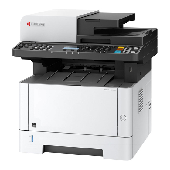
Page 23: Part Names
2S0/2S1/2S2/2S3/2S4/2S5/2SG/2SH/3RA 1-2 Part Names (1) Machine Exterior 1 Document Processor 9 Original Tray 2 Inner Tray 10 Original Width Guides 3 Eject Stopper 11 Slit Glass 4 Cassette 1 12 Operation Panel 5 Power Switch 13 Contact glass 6 Front Cover Open Button 14 Original Size Indicator Plates 7 Original Eject Table 15 Rear cover... - Page 24 2S0/2S1/2S2/2S3/2S4/2S5/2SG/2SH/3RA (2) Connectors/Interior 9 10 1. TEL Connector 7. Paper Width Guides 2. LINE Connector 8. USB Memory Slot 3. USB Interface Connector 9. Multi Purpose Tray 10. Sub Tray 4. Network Interface Connector 11. Paper Guides 5. Feed Cover 12.
-
Page 25: With Optional Equipments Attached
2S0/2S1/2S2/2S3/2S4/2S5/2SG/2SH/3RA 13. Toner Container Release Button 14. Toner Container (3) With Optional Equipments Attached 1. Cassette 2 2. Cassette 3... - Page 26 2S0/2S1/2S2/2S3/2S4/2S5/2SG/2SH/3RA (4) Operation Panel (TSI) Select the function. 10:10 Copy Send Removable Job Box Address Memory Status Task Screen 1. [Home] key: Displays the Home screen. 2. [Status/Job Cancel] key: Displays the Status/Job Cancel screen. 3. [System Menu/Counter] key: Displays the System Menu/Counter screen. 4.
- Page 27 2S0/2S1/2S2/2S3/2S4/2S5/2SG/2SH/3RA (5) Operation Panel Keys (LCD) 1. [Status/Job Cancel] key: Displays the Status/Job Cancel screen. 2. [Document Box/USB] key: Displays the Document Box/USB screen. 3. [System Menu/Counter] key: Displays the System Menu/Counter screen. 4. [FAX] key: Displays the FAX screen. 5.
- Page 28 2S0/2S1/2S2/2S3/2S4/2S5/2SG/2SH/3RA 21, 22 18. [Function Menu] key: Displays the function menu screen. 19. [Back] key: Returns to the previous display. 20. [Attention] indicator: Lights or blinks when an error occurs and a job is stopped. 21. Arrow keys: Increments or decrements numbers, or selects menu in the message display. In addition, moves the cursor when entering the characters.
-
Page 29: Overview Of Optional Equipment
2S0/2S1/2S2/2S3/2S4/2S5/2SG/2SH/3RA 1-3 Overview of Optional Equipment The following optional equipment is available for the machine. (1) Expansion Memory (2) PF-1100 Software option (3) Card Authentication Kit (B) (4) UG-33 (5) SD/SDHC Memory Card (6) USB Keyboad 1-13... -
Page 30: Expansion Memory
2S0/2S1/2S2/2S3/2S4/2S5/2SG/2SH/3RA (1) Expansion Memory The machine can perform the more multiple jobs simultaneously by adding more memories. You can increase the machine's memory up to 1,536 MB by plugging in the optional memory modules. Precautions for Handling the Memory Modules To protect electronic parts, discharge static electricity from your body by wearing an antistatic wrist strap, if possible, when you install the memory modules. -
Page 31: Sd/Sdhc Memory Card
2S0/2S1/2S2/2S3/2S4/2S5/2SG/2SH/3RA (2) PF-1100 "Paper Feeder" Maximum two 250-sheet paper feeder can be installed. (3) Card Authentication Kit(B) "Card Authentication Kit" User login administration can be performed using ID cards. To do so, it is necessary to register ID card information on the previously registered local user list. -
Page 32: Installation Environment
2S0/2S1/2S2/2S3/2S4/2S5/2SG/2SH/3RA 2 Installation 2-1 Environment Installation environment 1. Temperature: 50 to 90.5°F (10 to 32.5°C) (But humidity should be 70% or less when the temperature is 90.5°F (32.5°C).) 2. Humidity: 10 to 80%(But the temperature should be 86°F (30°C) or less when humidity is 80%.) 3. -
Page 33: Installing The Main Unit
2S0/2S1/2S2/2S3/2S4/2S5/2SG/2SH/3RA 2-2 Installing the main unit Installation procedures START Unpacking and checking bundled items Optional unit installation Connecting the Other Dvices Connecting the Interface Cable Default Setting Loading Paper Installing Software Turn the power on Output a report (Maintenance mode U000) Maintenance report User status report Clearing the counts... - Page 34 2S0/2S1/2S2/2S3/2S4/2S5/2SG/2SH/3RA (1) Unpacking and checking bundled items (1-1) Main unit Take out the main unit and accessories from the packing case. Remove the tape and cushioning materials for packing from the main unit. Figure 2-2 1. Right upper pad 8. Documents 2.
-
Page 35: Paper Feeder (Option)
2S0/2S1/2S2/2S3/2S4/2S5/2SG/2SH/3RA-1 (1-2) Paper Feeder (Option) Take the paper feeder out of the packing case. Remove the packing tape from the paper feeder. Figure 2-3 1. Left pad 5. Main unit storage bag 2. Right pad 6. Outer box 3. Main unit protective sheet 7. -
Page 36: Installing The Optional Equipment
2S0/2S1/2S2/2S3/2S4/2S5/2SG/2SH/3RA (2) Installing the optional equipment Install the necessary optional equipment in the main unit by referring to the installation procedures. (3) Connecting to other device Prepare the cables necessary to suit the environment and purpose of the machine use. When Connecting the Machine to the PC via USB When Connecting the Machine to the PC on the Network Network... -
Page 37: Usb Cable
2S0/2S1/2S2/2S3/2S4/2S5/2SG/2SH/3RA (4) Connecting to the cable (4-1) LAN Cable 1. Connect the LAN cable to the network interface connector. 2. Connect the other end of the cable to the hub or the PC. 3. Power on the machine and set the network. (4-2)USB cable 1. -
Page 38: Loading Paper
2S0/2S1/2S2/2S3/2S4/2S5/2SG/2SH/3RA (5) Loading Paper 1. Pull the cassette out of the main unit. NOTE When the bottom plate is lifted, push it until locked. 2. Adjust the paper length guide of the cassette. - Page 39 2S0/2S1/2S2/2S3/2S4/2S5/2SG/2SH/3RA NOTE In case of using Folio, Oficio ?or Legal 3. Adjust the paper width guides of the cassette 4. Load paper. 5. Insert the cassette slowly into the main unit as far as it goes. 6. Set the paper size and the paper type from the system menu. IMPORTANT Load it with the printing side facing down Before loading paper in the cassette, fan the paper taken from a new package to separate it.
-
Page 40: Precaution For Loading Paper
2S0/2S1/2S2/2S3/2S4/2S5/2SG/2SH/3RA-1 Precaution for Loading Paper Separate the paper taken out of the package in the following procedures before loading it in the cassette. Separate paper and align the edge of the paper in a flat place. In addition, note the following. In case of paper fold or curl, stretch it in a straight line. -
Page 41: Setting Date And Time
2S0/2S1/2S2/2S3/2S4/2S5/2SG/2SH/3RA (7) Default (TSI model) Before using this machine, configure such settings as date and time, network configuration, and energy saving functions as needed. The Machine Setup Wizard is launched when the equipment is turned on for the first time after being installed. -
Page 42: Wired Network Setting
2S0/2S1/2S2/2S3/2S4/2S5/2SG/2SH/3RA (7-2)Network Settings Wired network setting The machine is equipped with network interface, which is compatible with network protocols such as TCP/IP (IPv4), TCP/IP (IPv6), NetBEUI, and IPSec. It enables network printing on the Windows, Macintosh, UNIX and other platforms. Set up TCP/IP (IPv4) to connect to the Windows network. -
Page 43: Wireless Network Setting
2S0/2S1/2S2/2S3/2S4/2S5/2SG/2SH/3RA Wireless network setting When the wireless network function is available on the machine and the connection settings are configured, it is possible to print or send in a wireless network (wireless LAN) environment. The configuration methods are as follows: Configuration Method Descriptions Configuring the Connection from... - Page 44 2S0/2S1/2S2/2S3/2S4/2S5/2SG/2SH/3RA (7) Default (LCD model) Before using this machine, configure such settings as date and time, network configuration, and energy saving functions as needed. NOTE The default settings of the machine can be changed in System Menu. Refer to the operation guide of the main unit about the items which can set from the system menu. (7-1) Setting Date and Time Follow the steps below to set the local date and time at the place of installation.
-
Page 45: Configuring The Wired Network
2S0/2S1/2S2/2S3/2S4/2S5/2SG/2SH/3RA (7-2)Network Settings Configuring the Wired Network The machine is equipped with network interface, which is compatible with network protocols such as TCP/IP (IPv4), TCP/IP (IPv6), NetBEUI, and IPSec. It enables network printing on the Windows, Macintosh, UNIX and other platforms. Set up the network connection via TCP/IP (IPv4). - Page 46 2S0/2S1/2S2/2S3/2S4/2S5/2SG/2SH/3RA NOTE Ask your network administrator for the IP address in advance, and have it ready when you configure this setting. In the following cases, set the IP address of DNS server by using Command Center RX. When using the host name with the "DHCP" set to [Off] When using the DNS server other than the DNS server, IP address of which is assigned by the DHCP auto- matically, With regard to the IP address setting of the DNS server, refer to Command Center RX operating proce-...
- Page 47 2S0/2S1/2S2/2S3/2S4/2S5/2SG/2SH/3RA (7-3)Altitude Adjustment Setting Execute [Altitude Adjustment] from the System Menu when setting up at a high altitude place. When the usage envi- ronment is at altitudes of sea level 1,000m or more and the printing quality is declined, set the altitude adjustment mode and you can recover the print quality.
-
Page 48: Installing Software
File Management Utility This makes it possible to send and save a scanned document to a specified network folder. KYOCERA Net Direct Print This makes it possible to print a PDF file without starting Adobe Acrobat/Reader. FONTS ○... - Page 49 2S0/2S1/2S2/2S3/2S4/2S5/2SG/2SH/3RA (9) Output Maintenance Report (Executing Maintenance mode U000) (For Service) 1. Input "10871087" using the numeric keys to enter the maintenance mode. 2. Enter "000" by using the numeric keys and press the [Start] key. 3. Select [Maintenance] and press the [Start] key to output the status report. 4.
-
Page 50: Machine Design
2S0/2S1/2S2/2S3/2S4/2S5/2SG/2SH/3RA 3 Machine Design Cross-section view (1) Main unit + Document processor + Paper feeder (option) Original path Paper path Optical path Paper path (Option) Figure 3-1 1. Cassette paper feed 7. Conveying/Transfer section 2. MP paper feed section 8. Fuser section 3. -
Page 51: Electric Parts
2S0/2S1/2S2/2S3/2S4/2S5/2SG/2SH/3RA-1 The configuration of the electrical components (1) Electric parts (1-1) Machine left side Figure 3-2 1. Left side fan motor 2. Scanner motor 3. Temp/Humid sensor 4. Fuser pressure release motor... - Page 52 2S0/2S1/2S2/2S3/2S4/2S5/2SG/2SH/3RA (1-2) Machine right side Figure 3-3 1. Paper feed motor A. Main/Engine PWB 2. Paper feed clutch B. Power source PWB 3. Registration clutch C. Wi-Fi PWB 4. Developer clutch 5. Right side fan motor 6. MP solenoid 7. Power switch...
- Page 53 2S0/2S1/2S2/2S3/2S4/2S5/2SG/2SH/3RA (1-3) Document processor Figure 3-4 1. PF main PWB 3. PF conveying clutch 2. PF paper feed clutch (1-4) Paper feeder (option) Figure 3-5 1. PF paper feed motor 3. PF feed clutch 2. PF paper feed clutch...
-
Page 54: Power Source Pwb
2S0/2S1/2S2/2S3/2S4/2S5/2SG/2SH/3RA (2) Descriptions about the major PWBs (2-1) Main/Engine PWB It controls the software for interface, image data processing, etc. and hardware for the image scanner, operation unit, high voltage/ bias output, paper conveying mechanism, etc. Figure 3-6 (2-2) High-voltage PWB Output the main charger high-voltage, the developer bias, the transfer bias, separa- tion bias and the transfer cleaning bias. - Page 55 2S0/2S1/2S2/2S3/2S4/2S5/2SG/2SH/3RA (2-4) Operation panel PWB (TSI) It consists of the relay wiring circuit for the main/engine PWB, the operation key PWB(L/R) and the touch panel. Figure 3-9 (2-5) Operation panel PWB (LCD) It consists of the LCD, LED indicators, the key switches.
-
Page 56: Electric Parts Layout
2S0/2S1/2S2/2S3/2S4/2S5/2SG/2SH/3RA (3) Electric parts layout (3-1) PWBs Laser scanner unit Fuser unit Main body Drum unit Developer unit Paper feeder Machine left side / Machine inside / Machine right side Figure 3-11... - Page 57 2S0/2S1/2S2/2S3/2S4/2S5/2SG/2SH/3RA 1. FAX PWB *1 ......... Modulate/demodulate of image data, compress/decompress, change resolution and smoothing 2. Main/Engine PWB ........ It controls the software for the interface and image data process- ing, and controls the hardware such as the image scanner unit, operation section, high voltage/bias output, paper conveying mechanism, etc.
- Page 58 2S0/2S1/2S2/2S3/2S4/2S5/2SG/2SH/3RA Part name table Name used in service manual Name used in parts list Part. No. PARTS FAX UNIT E SP 303PA94011 FAX PWB*1 PARTS FAX UNIT U SP 302R794340 PARTS FAX UNIT J SP 302R794330 PARTS PWB MAIN ENGINE ASSY SP 302S094060 PARTS PWB MAIN ENGINE ASSY EU SP 302S094070...
-
Page 59: Sensors And Switches
2S0/2S1/2S2/2S3/2S4/2S5/2SG/2SH/3RA (3-2) Sensors and Switches Document Laser scanner unit processer Fuser unit Main body Drum unit Developer unit Paper feeder Machine left side / Machine inside / Machine right side 3-10... - Page 60 2S0/2S1/2S2/2S3/2S4/2S5/2SG/2SH/3RA-2 1. Power switch ........Switching on and off the main/engine PWB and the operation panel PWB, etc. 2. Paper sensor ........Detecting the presence of paper on the cassette. 3. Registration sensor ......Controlling the timing to start the secondary paper feeding. 4.
- Page 61 2S0/2S1/2S2/2S3/2S4/2S5/2SG/2SH/3RA Conveying cover switchPart name table Name used in service manual Name used in parts list Part. No. Power switch PARTS PWB SWITCH ASSY SP 302RV94130 Paper sensor PARTS SENSOR OPT. SP 302P794010 PARTS UNIT HIGH VOLTAGE SP 302RV94190 Registration sensor PARTS UNIT HIGH VOLTAGE J SP 302RV94200 PARTS PWB ASSY EMPTY SENSOR...
- Page 62 2S0/2S1/2S2/2S3/2S4/2S5/2SG/2SH/3RA (3-3) Motors Document Laser scanner unit processer Fuser unit Main body Drum unit Developer unit Paper feeder Machine left side / Machine inside / Machine right side 3-13...
- Page 63 2S0/2S1/2S2/2S3/2S4/2S5/2SG/2SH/3RA 1. Main motor ........... The paper feed and conveying mechanism drive 2. Fuser pressure release motor ....Fuser pressure release drive 3. Scanner motor ........Driving the optical section. 4. Rght side fan ........Cooling inside the machine (right side) 5.
- Page 64 2S0/2S1/2S2/2S3/2S4/2S5/2SG/2SH/3RA (3-4) Others Document Laser scanner unit processer Fuser unit Main body Drum unit Developer unit Paper feeder Machine left side / Machine inside / Machine right side 3-15...
- Page 65 2S0/2S1/2S2/2S3/2S4/2S5/2SG/2SH/3RA 1. Developer clutch ........Controlling the drive to developer unit. 2. Registration clutch ....... Registration roller drive control 3. Paper feed clutch ......... Controlling the drive of cassette paper feed 4. MP solenoid ......... Controlling the drive of MP lift guide 5.
-
Page 66: Drive System
2S0/2S1/2S2/2S3/2S4/2S5/2SG/2SH/3RA Drive system (1) Drive system for the paper conveying Figure 3-12 A. Primary paper feed 8. Eject roller 1. Paper feed roller 9. Main motor 10. PF paper feed roller B. Developer unit 11. PF conveying motor 2. Developer roller 3. -
Page 67: Drum Drive
2S0/2S1/2S2/2S3/2S4/2S5/2SG/2SH/3RA (2) Each section drive (2-1) Primary paper feed drive Main motor Middle roller Paper feed clutch Paper feed roller Figure 3-13 (2-2) Drum drive Cleaning roller Main motor Drum Figure 3-14 3-18... -
Page 68: Developer Drive
2S0/2S1/2S2/2S3/2S4/2S5/2SG/2SH/3RA (2-3) Developer drive Developer screw A Developer roller Developer screw B Developer clutch Main motor Figure 3-15 (2-4) Fuser unit drive Fuser belt Lower eject roller Main motor Figure 3-16 3-19... -
Page 69: Mechanical Construction
2S0/2S1/2S2/2S3/2S4/2S5/2SG/2SH/3RA Mechanical construction (1) Paper feed section The paper feed section consists of the cassette feed section which feeds from the paper cassette and the MP tray feed section which feeds from the MP tray. (1-1) Cassette paper feed section The cassette can 300 sheets paper (64g/m2) or 250 sheets paper (80g/m2). -
Page 70: Block Diagram
2S0/2S1/2S2/2S3/2S4/2S5/2SG/2SH/3RA Block diagram Main/ Engine PWB CASPAPSE Paper sensor YC6-3 MAIMOTDIR YC9-1 MAIMOTRDYN YC9-2 Main motor MAIMOTCLKN YC9-3 MAIMOTREN YC9-4 FEEDCLURE Paper feed clutch YC10-4 Figure 3-19 3-21... -
Page 71: Mp Tray Paper Feed Section
2S0/2S1/2S2/2S3/2S4/2S5/2SG/2SH/3RA (1-2) MP tray paper feed section The MP tray can load 60 sheets paper (64 g/m ) or 50 sheets (80 g/m ). The paper on the MP tray is fed by rotating the MP paper feed roller while lifting up the MP bottom plate by the MP solenoid. Multi-feeding is also prevented by the effect of the MP separation pad. - Page 72 2S0/2S1/2S2/2S3/2S4/2S5/2SG/2SH/3RA Block diagram Main/ Engine PWB MPFPAPSE MP paper sensor YC6-6 MPFSOLRE MP solenoid YC21-4 MAIMOTDIR YC9-1 MAIMOTRDYN YC9-2 Main motor MAIMOTCLKN YC9-3 MAIMOTREN YC9-4 Figure 3-22 3-23...
-
Page 73: Optical Section
2S0/2S1/2S2/2S3/2S4/2S5/2SG/2SH/3RA (2) Optical section The optical section consists of the image scanner section for scanning the original and the laser scanner section to write the image. (2-1) Image scanner unit The original image is exposed by the exposure lamp (LED) and the reflection light is scanned by the CIS image sensor and converted to the electric signal. - Page 74 2S0/2S1/2S2/2S3/2S4/2S5/2SG/2SH/3RA Block diagram Main/ Engine PWB ISUHPSE Home position sensor YC31-3 ISUMOTA1 YC31-4 ISUMOTA2 YC31-5 Scanner motor ISUMOTB2 YC31-6 ISUMOTB1 YC31-7 SAAVO0 YC506-1 SAAVO1 YC506-3 SAAVO2 YC506-5 SAASP YC506-8 SAACLK YC506-10 SAALEDA YC506-11 SAALEDB YC506-12 SAALEDG YC506-13 SAALEDR YC506-14 Figure 3-25 3-25...
-
Page 75: Laser Scanner Unit
2S0/2S1/2S2/2S3/2S4/2S5/2SG/2SH/3RA (2-2) Laser scanner unit The charged drum surface is scanned by the laser emitted from the laser scanner units. The laser reflects to the polygon mirrors by rotating the polygon motor so that the laser scans horizontally to the image. The laser scanner unit has some lenses and mirrors, that adjust the diameter of the laser to focus the laser to the drum surface. - Page 76 2S0/2S1/2S2/2S3/2S4/2S5/2SG/2SH/3RA Block diagram Main/ Engine PWB PMOTREM YC3-3 PMOTRDYN Polygon motor YC3-4 PMOTCLKN YC3-5 VDATA2N YC505-1 VDATA2P YC505-2 VDATA1N YC505-3 VDATA1P YC505-4 SAMPLE2 APC PWB YC505-5 SAMPLE1 YC505-6 LSUENAN YC505-7 VCONT YC505-9 YC505-10 Figure 3-28 3-27...
- Page 77 2S0/2S1/2S2/2S3/2S4/2S5/2SG/2SH/3RA (3) Developer section (3-1) Developer unit The developer section consists of the developer roller forming the magnetic brush, the developer blade forming the thin layer by moving the toner, and the developer screw mixing up the toner. The toner density is adjusted by impressing the bias to the developer roller.
- Page 78 2S0/2S1/2S2/2S3/2S4/2S5/2SG/2SH/3RA Block diagram REGPAPSE YC16-4 MHVCNT YC16-5 HVCLK High voltage YC16-6 RTHVREM YC16-7 Developer GHVCNT YC16-8 DHVCNT YC16-9 THVCNT YC16-10 SHVCNT YC16-12 Main/ Engine PWB DLPCLURE Developer clutch YC10-6 MAIMOTDIR YC9-1 MAIMOTRDYN YC9-2 Main motor MAIMOTCLKN YC9-3 MAIMOTREN YC9-4 ITOEMPSE Toner sensor YC14-2 Figure 3-31...
-
Page 79: Drum Section
2S0/2S1/2S2/2S3/2S4/2S5/2SG/2SH/3RA (4) Drum section The drum section consists of the drum, the main charger roller unit, and the cleaning blade, etc. The drum surface is evenly charged to prepare forming the electrostatic latent image by emitting the laser beams. (4-1) Main charger unit The drum surface is evenly charged by the shield grid attached to the bottom of the unit. - Page 80 2S0/2S1/2S2/2S3/2S4/2S5/2SG/2SH/3RA Block diagram REGPAPSE YC16-4 MHVCNT Grid PWB YC16-5 HVCLK High voltage YC16-6 RTHVREM YC16-7 GHVCNT YC16-8 DHVCNT YC16-9 THVCNT YC16-10 SHVCNT YC16-12 Main/ Engine PWB MAIMOTDIR YC9-1 MAIMOTRDYN YC9-2 Mai motor MAIMOTCLKN YC9-3 MAIMOTREN YC9-4 Figure 3-34 3-31...
- Page 81 2S0/2S1/2S2/2S3/2S4/2S5/2SG/2SH/3RA (5) Conveying/Transfer and Separation section Conveying section conveys paper to the transfer and separation section after adjusting the paper position at the registration rollers. The transfer and separation section consists of the transfer roller and separation needles attached to the paper conveying unit.
- Page 82 2S0/2S1/2S2/2S3/2S4/2S5/2SG/2SH/3RA Block diagram REGPAPSE YC16-4 MHVCNT YC16-5 HVCLK High voltage YC16-6 RTHVREM YC16-7 GHVCNT YC16-8 Transfer DHVCNT YC16-9 Separate THVCNT YC16-10 SHVCNT YC16-12 Main/ Engine PWB REGCLURE Registration clutch YC10-2 MAIMOTDIR YC9-1 MAIMOTRDYN YC9-2 Main motor MAIMOTCLKN YC9-3 MAIMOTREN YC9-4 Figure 3-37 3-33...
-
Page 83: Fuser Section
2S0/2S1/2S2/2S3/2S4/2S5/2SG/2SH/3RA (6) Fuser section Paper from the transfer and separation section is pinched between the fuser belt and the press roller. The fuser belt is heated by the fuser heater and pressed by the press roller pressed by the fuser pressure spring. - Page 84 2S0/2S1/2S2/2S3/2S4/2S5/2SG/2SH/3RA Block diagram FUSTMPSE2 Fuser edge thermistor YC19-10 FUSROTSE Rotation detect sensor YC19-3 FUSTMPSE10 YC2-5 FUSTMPSE1A YC2-8 Thermo pile TPSDA YC2-9 TPSCL YC2-10 Thermocut ZCROSS YC102-2 YC20-7 Heater HEAT YC102-1 YC20-8 STANDBYN YC20-9 Low voltage RELAY YC20-10 power source PWB Main/ Engine PWB EXIPAPSE...
-
Page 85: Eject And Feedshift Section
2S0/2S1/2S2/2S3/2S4/2S5/2SG/2SH/3RA (7) Eject and feedshift section The eject and feedshift section consists of the paper path from the fuser section to the inner tray or the duplex conveying section. Components parts 1. Upper eject roller 2. Upper eject pulley 3. Eraser brush 4. - Page 86 2S0/2S1/2S2/2S3/2S4/2S5/2SG/2SH/3RA Block diagram Main/ Engine PWB EXISOLRE Eject solenoid YC1-2 MAIMOTDIR YC9-1 MAIMOTRDYN YC9-2 Main motor MAIMOTCLKN YC9-3 MAIMOTREN YC9-4 Figure 3-43 3-37...
-
Page 87: Duplex Conveying Section
2S0/2S1/2S2/2S3/2S4/2S5/2SG/2SH/3RA (8) Duplex conveying section The duplex conveying section consists of the paper conveying path to forward the paper from the eject and feedshift section in the duplex print to the paper conveying section. Components parts 1. Lower eject roller 2. - Page 88 2S0/2S1/2S2/2S3/2S4/2S5/2SG/2SH/3RA Block diagram Main/ Engine PWB EXIPAPSE Eject sensor YC19-6 MAIMOTDIR YC9-1 MAIMOTRDYN YC9-2 Main motor MAIMOTCLKN YC9-3 MAIMOTREN YC9-4 Figure 3-46 3-39...
-
Page 89: Document Processor
2S0/2S1/2S2/2S3/2S4/2S5/2SG/2SH/3RA (9) Document processor The original feed section consisting of the parts in the figure, feeds and conveys the original on the original tray to the original conveying section by the rotation of the DP forwarding pulley and DP feed roller. The 2nd side of the conveyed original is scanned *1 when passing the CIS and the 1st side at the optical section (CIS) in the main unit when passing the DP slit glass. - Page 90 2S0/2S1/2S2/2S3/2S4/2S5/2SG/2SH/3RA Block diagram Main/ Engine PWB YC34-15 *1 DPCOVER DP open/close sensor YC34-12 *1 DPMOTA1 YC33-1 DPMOTA2 YC33-2 DP paper feed motor DPMOTB2 YC33-3 DPMOTB1 YC33-4 DPREGCLURE DP paper feed clutch YC33-6 ORGSETSE YC34-12 *1 DP original detect sensor YC34-9 *2 YC34-9 *1 DPFEEPAPSE DP paper feed sensor...
- Page 91 2S0/2S1/2S2/2S3/2S4/2S5/2SG/2SH/3RA (10)Paper feeder (option) The cassette can 300 sheets paper (64 g/m2) or 250 sheets paper (80 g/m2). Paper fed from the cassette is picked up by the rotation of the pickup roller and is conveyed to the main unit by the rotation of the paper feed roller and conveying roller.
- Page 92 2S0/2S1/2S2/2S3/2S4/2S5/2SG/2SH/3RA Block diagram Main/ Engine PWB PFEED PF feed sensor YC7-3 PF main PWB PF paper sensor NC-1 TMOTRDYN YC4-1 TMOTCLK YC4-2 PF conveying motor TMOTDRVN YC4-3 FEEDCLN PF paper feed clutch YC2-2 TRNSCLN PF conveying clutch YC2-4 Figure 3-52 3-43...
-
Page 93: Maintenance
2S0/2S1/2S2/2S3/2S4/2S5/2SG/2SH/3RA 4 Maintenance 4-1 Precautions for the maintenance (1) Precautions Before disassembling the main unit, press the main power switch to turn the power off. Make sure that the power lamp on the operation panel is off and unplug the power cord from the wall outlet. Then, start the disassembly. - Page 94 2S0/2S1/2S2/2S3/2S4/2S5/2SG/2SH/3RA (4) Screening of the toner container Look at the screening film on the brand protection seal affixed to the toner container through the windows of the validation viewer. Look at the screening film through two windows to check the genuineness. A black-colored band when seen through the the anti-counterfeit film portion left side window ( mark).
- Page 95 2S0/2S1/2S2/2S3/2S4/2S5/2SG/2SH/3RA-1 4-2 Maintenance parts (1) Maintenance kits Maintenance part name Part No. Name used in service manual Name used in parts list MK-1150 MK-1150/MAINTENANCE KIT 1702RV0NL0 MK-1151 MK-1151/MAINTENANCE KIT 1702RV0JP0 MK-1152 MK-1152/MAINTENANCE KIT 1702RV0US0 MK-1154 MK-1154/MAINTENANCE KIT 1702RV0AS0 (100,000 image) DRUM UNIT Developer unit (2) Executing the maintenance mode after replacing the...
- Page 96 2S0/2S1/2S2/2S3/2S4/2S5/2SG/2SH/3RA-1 (4) Periodic maintenance Procedures Check the maintenance counts by the maintenance mode U901. CH:Check / CL:Clean / AD:Adjust / LU:Lubrication / RE:Replace Parts name Parts No. PM maintenance (x1000 counts) Remark Set UP User Call Please do not use spray containing flamable gas for air-blow or air-brush purposes. IMAGE QUALITY MK-1150 1702RV0NL0...
- Page 97 2S0/2S1/2S2/2S3/2S4/2S5/2SG/2SH/3RA 4-3Maintenance parts replacement procedures When it is necessary to replace parts is needed due to malfunction, etc., replace the service parts in the fol- lowing procedures. (1) Cassette paper feed section (1-1)Detaching and reattaching the Paper feed roller Procedures 1.
- Page 98 2S0/2S1/2S2/2S3/2S4/2S5/2SG/2SH/3RA 5. Check or replace the paper feeder roller assembly (a) (paper feed roller, pick up roller), and then reattach the parts in the original position. Attention: When reattaching to the paper feed roller assembly (a), make sure to align the head (c) of the feed shaft (b) to the oval (d) of the paper feed roller assembly.
- Page 99 2S0/2S1/2S2/2S3/2S4/2S5/2SG/2SH/3RA 3. Detach the retard roller (b) from the retard roller assembly (a). Figure 4-5 4. Check or replace the retard roller, reat- tach the detached parts in the original position. Attention: When attaching the retard roller assembly (a), make sure to attach the spring (c) to the protrusion (b) of the retard roller assembly.
- Page 100 2S0/2S1/2S2/2S3/2S4/2S5/2SG/2SH/3RA (1-3)Detaching and reattaching the MP paper feed pulley Procedures 1. Detach the cassette 2. Open the front cover (a) and detach the strap by using pliers. 3. Remove the stop ring (c). Figure 4-7 4. Open the front cover (a) to the bottom and detach the left side of cover fulcrum from the fulcrum shaft (b).
- Page 101 2S0/2S1/2S2/2S3/2S4/2S5/2SG/2SH/3RA 6. Remove four screws(M3x8S tight)(a), detach MP below frame(b). Figure 4-9 7. Pull the lock lever and the slide the paper feed roller shaft (b) to the right. 8. Detach the paper feed pulley (c). 9. Check or replace the paper feed pulley (c), and then reattach the parts which are detached in the original position.
- Page 102 2S0/2S1/2S2/2S3/2S4/2S5/2SG/2SH/3RA (2) Developer section (2-1)Detaching and reattaching the developer unit Procedures 1. Open the front cover (a). 2. Push down the developer release lever (b). Figure 4-12 3. Detach the developer unit (a). 4. Check or replace the developer unit (a), and then reattach the parts which are detached in the original position.
- Page 103 2S0/2S1/2S2/2S3/2S4/2S5/2SG/2SH/3RA (3) Drum section (3-1)Detaching and reattaching the drum unit Procedures 1. Open the front cover (a). 2. Push down the developer release lever (b). Figure 4-14 3. Detach the developer unit (a). Figure 4-15 4-11...
- Page 104 2S0/2S1/2S2/2S3/2S4/2S5/2SG/2SH/3RA 4. Detach the drum unit (a). 5. Check or replace the drum unit (a), and then reattach the parts which are detached in the original position. When replacing with the new drum unit, execute the following maintenance mode. U110 Clear the drum counter U120?Clear the drum drive distance coun- Attention: Execute the following maintenance modes...
- Page 105 2S0/2S1/2S2/2S3/2S4/2S5/2SG/2SH/3RA (3-2)Detaching and reattaching the main charger unit Procedures 1. Remove the tape (b) from the drum unit (a). 2. Open the eraser cover (c) Figure 4-17 3. Slide the edge (a) of the main charger unit. 4. Pull up the edge (a) of the main charger unit and detach it.
- Page 106 2S0/2S1/2S2/2S3/2S4/2S5/2SG/2SH/3RA (4) Transfer section (4-1)Detaching and reattaching the transfer roller unit Procedures 1. Open the front cover (a). 2. Push down the developer release lever (b). Figure 4-19 3. Detach the developer unit (a). Figure 4-20 4-14...
- Page 107 2S0/2S1/2S2/2S3/2S4/2S5/2SG/2SH/3RA 4. Detach the drum unit (b). Figure 4-21 5. Slide the transfer front guide (b) while pressing the release lever (a) and release the hook (c). 6. Remove the transfer front guide (b). Figure 4-22 4-15...
- Page 108 2S0/2S1/2S2/2S3/2S4/2S5/2SG/2SH/3RA 7. Remove the shaft (b) of transfer roller (a) from two transfer bushings (c). 8. Remove the gear Z17 (d) from the transfer roller (a). 9. Check or replace the transfer roller (a), and then reattach the parts which are detached in the original position.
- Page 109 2S0/2S1/2S2/2S3/2S4/2S5/2SG/2SH/3RA (5) Fuser section (5-1)Detaching and reattaching the fuser unit Procedures 1. Slightly pull out the cassette 2. Open the rear cover (a). 3. Open the cassette cover (c) and release the hook (d) of the left rear cover (b) in the direction of the arrow. 4.
- Page 110 2S0/2S1/2S2/2S3/2S4/2S5/2SG/2SH/3RA 6. After twisting the DIMM cover(a), remove it while sliding it Figure 4-26 7. Twist the right rear cover(a) and detach it while sliding it. Figure 4-27 4-18...
- Page 111 2S0/2S1/2S2/2S3/2S4/2S5/2SG/2SH/3RA 8. Remove two screws (a)(M3x8P tight) and detach the fuser wire cover (b). Figure 4-28 9. Disconnect the connector(a) from the low voltage power source PWB. 10. Disconnect the connector (b) from the main/ engine PWB. Figure 4-29 4-19...
- Page 112 2S0/2S1/2S2/2S3/2S4/2S5/2SG/2SH/3RA 11. Remove four screws (a) (M3×8S tight). Figure 4-30 12. Pull out the fuser unit (a) while holding the both ends of it. 13. Check or replace the fuser unit (a), and then reattach the parts which are detached in the original position. Attention: When detaching and reattaching, pay atten- tion not to burn by touching the hot section.
- Page 113 2S0/2S1/2S2/2S3/2S4/2S5/2SG/2SH/3RA 4-4Disassembly and Reassembly (1) Outer covers (1-1)Detaching and reattaching the left rear cover Procedures 1. Slightly pull out the cassette 2. Open the rear cover (a). 3. Open the cassette cover (c) and release the hook (d) of the left rear cover (b) in the direction of the arrow.
- Page 114 2S0/2S1/2S2/2S3/2S4/2S5/2SG/2SH/3RA (1-3)Detaching and reattaching the ISU left cover Procedures 1. Remove the screw(M3×10TP)(b). 2. While twisting the ISU left cover (a), release two hooks (c) in the direction of the arrow. 3. Release the protrusion (d) of the ISU left cover (a) in the direction of the arrow and detach it.
- Page 115 2S0/2S1/2S2/2S3/2S4/2S5/2SG/2SH/3RA (1-5)Detaching and reattaching the left cover Procedures 1. Detach the cassette 2. Open the front cover (a). 3. Release four hooks (b) at the front side of the left cover(a). Figure 4-36 4. Release two hooks (b) at the rear side of the left cover (a).
- Page 116 2S0/2S1/2S2/2S3/2S4/2S5/2SG/2SH/3RA (1-6)Detaching and reattaching the right cover Procedures 1. After twisting the DIMM cover(a), remove it while sliding it Figure 4-38 2. Twist the right rear cover(a) and detach it while sliding it. Figure 4-39 4-24...
- Page 117 2S0/2S1/2S2/2S3/2S4/2S5/2SG/2SH/3RA 3. Detach two hooks(b) at the front side of the right cover (a). Figure 4-40 4. Release three hooks (b) at the rear side of the right cover (a). 5. Tilt the right cover (a) and detach it. Figure 4-41 4-25...
- Page 118 2S0/2S1/2S2/2S3/2S4/2S5/2SG/2SH/3RA (1-7)Detaching and reattaching the front cover Procedures 1. Open the front cover (a) and detach the strap by using pliers. 2. Remove the stop ring (c). Figure 4-42 3. Open the front cover (a) to the bottom and detach the left side of cover fulcrum from the fulcrum shaft (b).
-
Page 119: Detaching And Reattaching The Rear Cover
2S0/2S1/2S2/2S3/2S4/2S5/2SG/2SH/3RA (1-8)Detaching and reattaching the rear cover Procedures 1. Open the rear cover (a) to align it to the position of the shaft (b) and detach it from the fulcrum (c) in the direction of the arrow. Figure 4-44 4-27... - Page 120 2S0/2S1/2S2/2S3/2S4/2S5/2SG/2SH/3RA (2) Optical section (2-1)Detaching and reattaching the laser scanner unit (LSU). Procedures 1. Slightly pull out the cassette 2. Open the rear cover (a). 3. Open the cassette cover (c) and release the hook (d) of the left rear cover (b) in the direction of the arrow.
- Page 121 2S0/2S1/2S2/2S3/2S4/2S5/2SG/2SH/3RA 7. Remove the screw(M3×10TP)(b). 8. While twisting the ISU left cover (a), release two hooks (c) in the direction of the arrow. 9. Release the protrusion (d) of the ISU left cover (a) in the direction of the arrow and detach it. Figure 4-47 10.
- Page 122 2S0/2S1/2S2/2S3/2S4/2S5/2SG/2SH/3RA 12. After twisting the DIMM cover(a), remove it while sliding it. Figure 4-49 13. Twist the right rear cover (a) and detach it while sliding it. Figure 4-50 4-30...
- Page 123 2S0/2S1/2S2/2S3/2S4/2S5/2SG/2SH/3RA 14. Detach the cassette 15. Open the front cover (a). 16. Detach two hooks (b) at the front side of the right cover (a). Figure 4-51 17. Release three hooks (b) at the rear side of the right cover (a). 18.
- Page 124 2S0/2S1/2S2/2S3/2S4/2S5/2SG/2SH/3RA 19. Remove the screw(M3×8S tight)(a), remove the ground terminal. Figure 4-53 20. Disconnect six connectors (b), the con- nector (c)*1, USB connector (d)*1, FFC (e) and FFC (f)*2 from the main/engine PWB (a). *1: TSI model only *2: 40 ppm model only Figure 4-54 4-32...
- Page 125 2S0/2S1/2S2/2S3/2S4/2S5/2SG/2SH/3RA 21. TSI model: remove the screw (M3×8B). 22. Remove two screws (b)(M4x12). 23. Align the image scanner unit(c) and document processor (d) in the direction of the arrow to release the hooks and detach them. Figure 4-55 24. Remove two screws(M3x8S tight)(a), detach ISU left holder(b).
- Page 126 2S0/2S1/2S2/2S3/2S4/2S5/2SG/2SH/3RA 25. Disconnect the relay connector (a) of the speaker. 26. Disconnect the connector (c) from the main/engine PWB (b). Figure 4-57 27. Remove two screws (a)(M3x8S tight) and detach the FAX PWB assembly(b). 28. Lift up the hook (d) of FAX PWB lower cover (c) and detach it while sliding it in the direction of the arrow.
- Page 127 2S0/2S1/2S2/2S3/2S4/2S5/2SG/2SH/3RA 29. Remove the screw(M3x8P tight)(a), detach the speaker holder(b). Figure 4-59 30. Remove three screws(M3x8S tight)(a), detach ISU right holder(b). Figure 4-60 4-35...
- Page 128 2S0/2S1/2S2/2S3/2S4/2S5/2SG/2SH/3RA-1 31. Detach the Wi-Fi PWB (a). 32. Remove the wire from the wire guide (b). 33. Slid the wire guide (b), release the hook (c) and remove it. Figure 4-61 34. Open the top cover (a). 35. Remove the stop ring(b) and detach the upper cover rack (c) from the upper cover (a).
- Page 129 2S0/2S1/2S2/2S3/2S4/2S5/2SG/2SH/3RA-1 36. Remove two screws(M3×8TP)(a) and remove the eject tray (b) in the upper direction. Figure 4-63 37. Disconnect the connector (b) and the FFC (c) from the main/engine PWB (a). 38. Detach the wire from the clamp (d). Figure 4-64 4-37...
- Page 130 2S0/2S1/2S2/2S3/2S4/2S5/2SG/2SH/3RA-1 39. Remove four screws (M3×6TP)(b) from the laser scanner unit (a). 40. Check or replace the laser scanner unit (a), and then reattach the parts which are detached in the original position. Figure 4-65 IMPORTANT When securing the laser scanner unit with screws, execute it in the order of the figure to the right.
- Page 131 2S0/2S1/2S2/2S3/2S4/2S5/2SG/2SH/3RA (2-2)Detaching and reattaching the image scanner unit (ISU) Procedures 1. Slightly pull out the cassette 2. Open the rear cover (a). 3. Open the cassette cover (c) and release the hook (d) of the left rear cover (b) in the direction of the arrow. 4.
- Page 132 2S0/2S1/2S2/2S3/2S4/2S5/2SG/2SH/3RA 7. Remove the screw(M3×10TP)(b). 8. While twisting the ISU left cover (a), release two hooks (c) in the direction of the arrow. 9. Release the protrusion (d) of the ISU left cover (a) in the direction of the arrow and detach it. Figure 4-69 10.
- Page 133 2S0/2S1/2S2/2S3/2S4/2S5/2SG/2SH/3RA 12. After twisting the DIMM cover(a), remove it while sliding it Figure 4-71 13. Twist the right rear cover (a) and detach it while sliding it. Figure 4-72 4-41...
- Page 134 2S0/2S1/2S2/2S3/2S4/2S5/2SG/2SH/3RA 14. Detach the cassette 15. Open the front cover (a). 16. Detach two hooks (b) at the front side of the right cover (a). Figure 4-73 17. Release three hooks (b) at the rear side of the right cover (a). 18.
- Page 135 2S0/2S1/2S2/2S3/2S4/2S5/2SG/2SH/3RA 19. Remove the screw(M3×8S tight)(a), remove the ground terminal. Figure 4-75 20. Disconnect six connectors (b), the con- nector (c)*1, USB connector (d)*1, FFC (e) and FFC (f)*2 from the main/engine PWB (a). *1: TSI model only *2: 40 ppm model only Figure 4-76 4-43...
- Page 136 2S0/2S1/2S2/2S3/2S4/2S5/2SG/2SH/3RA 21. Open the document processor (a). 22. Lift up the document processor (a) in the direction of the arrow and detach the hinge (b) from the main unit. Figure 4-77 23. TSI model: remove the screw (M3×8B). 24. Remove two screws (b)(M4x12). 25.
- Page 137 2S0/2S1/2S2/2S3/2S4/2S5/2SG/2SH/3RA (2-3)Detaching and reattaching the operation panel (TSI model) Procedures 1. Open the document processor. 2. While lifting up the leading edge, slide two points of the operation covers (b) in the direction of the arrow. 3. Detach the operation panel cover (b) from the operational section (a).
- Page 138 2S0/2S1/2S2/2S3/2S4/2S5/2SG/2SH/3RA 6. Remove two screws (c) (M3×8S tight). 7. Release two hooks (b) by using a flat- head screwdriver (d). 8. Open the operational cover (a) while lift- ing up the front side of it. Figure 4-81 9. Turn over the operation cover (a). 10.
- Page 139 2S0/2S1/2S2/2S3/2S4/2S5/2SG/2SH/3RA (2-4)Detaching and reattaching the operation panel (LCD model) Procedures 1. Open the document processor. 2. Release two hooks (b) by using a flat- head screwdriver (c). 3. Open the operational cover (a) while lift- ing up the front side of it. Figure 4-83 4.
- Page 140 2S0/2S1/2S2/2S3/2S4/2S5/2SG/2SH/3RA (2-5)Detaching and reattaching the ISU top frame Procedures 1. Remove two screws(c). 2. Release five protrusions (d) of the ISU upper frame in the direction of arrow. 3. Release three hooks (f) of the ISU upper frame from the fixed section (e) of the ISU lower frame while lifting up the rear side of ISU upper frame.
- Page 141 2S0/2S1/2S2/2S3/2S4/2S5/2SG/2SH/3RA (3) Drive section (3-1)Detaching and reattaching the main motor Procedures 1. Slightly pull out the cassette 2. Open the rear cover (a). 3. Open the cassette cover (c) and release the hook (d) of the left rear cover (b) in the direction of the arrow. 4.
- Page 142 2S0/2S1/2S2/2S3/2S4/2S5/2SG/2SH/3RA 7. Twist the ISU right cover (a) and release two hooks (b) in the direction of the arrow. 8. Release the protrusion (c) of ISU right cover (a) in the direction of the arrow and detach it. Figure 4-89 9.
- Page 143 2S0/2S1/2S2/2S3/2S4/2S5/2SG/2SH/3RA 10. Twist the right rear cover (a) and detach it while sliding it. Figure 4-91 11. Detach the cassette 12. Open the front cover (a). 13. Detach two hooks (b) at the front side of the right cover (a). Figure 4-92 4-51...
- Page 144 2S0/2S1/2S2/2S3/2S4/2S5/2SG/2SH/3RA 14. Release three hooks (b) at the rear side of the right cover (a). 15. Tilt the right cover (a) and detach it. Figure 4-93 16. Remove the screw(M3×8Ptight) (b) and three screws(M3×8Stight)(c) securing the low voltage power source PWB cover (a) .
- Page 145 2S0/2S1/2S2/2S3/2S4/2S5/2SG/2SH/3RA 18. Disconnect the connector (a). 19. Remove three screws(M3×8Stight)(b), detach the main motor(c). 20. Check or replace the main motor(c), and then reattach the parts which are detached in the original position. Figure 4-95 4-53...
- Page 146 2S0/2S1/2S2/2S3/2S4/2S5/2SG/2SH/3RA (3-2)Detaching and reattaching the fuser pressure release drive unit Procedures 1. Slightly pull out the cassette 2. Open the rear cover (a). 3. Open the cassette cover (c) and release the hook (d) of the left rear cover (b) in the direction of the arrow. 4.
- Page 147 2S0/2S1/2S2/2S3/2S4/2S5/2SG/2SH/3RA 7. Remove the screw(M3×10TP)(b). 8. While twisting the ISU left cover (a), release two hooks (c) in the direction of the arrow. 9. Release the protrusion (d) of the ISU left cover (a) in the direction of the arrow and detach it. Figure 4-98 10.
- Page 148 2S0/2S1/2S2/2S3/2S4/2S5/2SG/2SH/3RA 13. Release two hooks (b) at the rear side of the left cover (a). 14. While tilting the left cover (a), detach it in the direction of the arrow. Figure 4-100 15. Disconnect the connector (a). Figure 4-101 4-56...
- Page 149 2S0/2S1/2S2/2S3/2S4/2S5/2SG/2SH/3RA 16. Open the front cover (a). 17. Push down the developer release lever (b). Figure 4-102 18. Detach the developer unit (a). Figure 4-103 4-57...
- Page 150 2S0/2S1/2S2/2S3/2S4/2S5/2SG/2SH/3RA 19. Detach the drum unit (b). Figure 4-104 20. Stand the main unit so that you can see the bottom side. 21. Remove four screws(M3x8P tight)(a) and remove the front stay(b). Figure 4-105 4-58...
- Page 151 2S0/2S1/2S2/2S3/2S4/2S5/2SG/2SH/3RA 22. Tilt the DU assembly (a) and detach two stoppers(b) while pushing them inside. 23. Lift down the DU assembly(a) to the bottom and pull it toward you to detach Figure 4-106 24. Remove two screws (a)(M3x8S tight). 25. Release the hook(b) and detach the fuser pressure release drive unit(c).
- Page 152 2S0/2S1/2S2/2S3/2S4/2S5/2SG/2SH/3RA (3-3)Detaching and reattaching the MP solenoid (front side) Procedures 1. Slightly pull out the cassette 2. Open the rear cover (a). 3. Open the cassette cover (c) and release the hook (d) of the left rear cover (b) in the direction of the arrow. 4.
- Page 153 2S0/2S1/2S2/2S3/2S4/2S5/2SG/2SH/3RA 7. Twist the ISU right cover (a) and release two hooks (b) in the direction of the arrow. 8. Release the protrusion (c) of ISU right cover (a) in the direction of the arrow and detach it. Figure 4-110 9.
- Page 154 2S0/2S1/2S2/2S3/2S4/2S5/2SG/2SH/3RA 10. Twist the right rear cover (a) and detach it while sliding it. Figure 4-112 11. Detach the cassette 12. Open the front cover (a). 13. Detach two hooks (b) at the front side of the right cover (a). Figure 4-113 4-62...
- Page 155 2S0/2S1/2S2/2S3/2S4/2S5/2SG/2SH/3RA 14. Release three hooks (b) at the rear side of the right cover (a). 15. Tilt the right cover (a) and detach it. Figure 4-114 16. Disconnect the connector (a), and detach one screw (M3x8S tight)(b). 17. Detach the MP solenoid (c). 18.
- Page 156 2S0/2S1/2S2/2S3/2S4/2S5/2SG/2SH/3RA (3-4)Detaching reattaching the clutch. Procedures 1. Slightly pull out the cassette 2. Open the rear cover (a). 3. Open the cassette cover (c) and release the hook (d) of the left rear cover (b) in the direction of the arrow. 4.
- Page 157 2S0/2S1/2S2/2S3/2S4/2S5/2SG/2SH/3RA 7. Twist the ISU right cover (a) and release two hooks (b) in the direction of the arrow. 8. Release the protrusion (c) of ISU right cover (a) in the direction of the arrow and detach it. Figure 4-118 9.
- Page 158 2S0/2S1/2S2/2S3/2S4/2S5/2SG/2SH/3RA 10. Twist the right rear cover (a) and detach it while sliding it. Figure 4-120 11. Detach the cassette 12. Open the front cover (a). 13. Detach two hooks (b) at the front side of the right cover (a). Figure 4-121 4-66...
- Page 159 2S0/2S1/2S2/2S3/2S4/2S5/2SG/2SH/3RA 14. Release three hooks (b) at the rear side of the right cover (a). 15. Tilt the right cover (a) and detach it. Figure 4-122 16. Disconnect three connector(a) of each clutch. Figure 4-123 4-67...
- Page 160 2S0/2S1/2S2/2S3/2S4/2S5/2SG/2SH/3RA 17. Remove two screws(M3x8S tight)(a), detach the clutch cover(b). 18. Detach the developer clutch (c) and registration clutch (d). Figure 4-124 19. Remove the screw(M3x8P tight)(a) and deatch the power switch(b). Figure 4-125 4-68...
- Page 161 2S0/2S1/2S2/2S3/2S4/2S5/2SG/2SH/3RA 20. Remove three screws(M3x8S tight)(a) and remove the cover (b). 21. Detach the paper feed clutch (c). 22. Check or replace the clutch, and reat- tach the parts which are detached in the original position. Figure 4-126 *: Attach the developer clutch (a) and the registration clutch (b) with the notches (c) facing down, and attach the cover.
- Page 162 2S0/2S1/2S2/2S3/2S4/2S5/2SG/2SH/3RA (3-5)Detaching and reattaching the eject solenoid Procedures 1. Slightly pull out the cassette 2. Open the rear cover (a). 3. Open the cassette cover (c) and release the hook (d) of the left rear cover (b) in the direction of the arrow. 4.
- Page 163 2S0/2S1/2S2/2S3/2S4/2S5/2SG/2SH/3RA 7. Remove the screw(M3×10TP)(b). 8. While twisting the ISU left cover (a), release two hooks (c) in the direction of the arrow. 9. Release the protrusion (d) of the ISU left cover (a) in the direction of the arrow and detach it. Figure 4-130 10.
- Page 164 2S0/2S1/2S2/2S3/2S4/2S5/2SG/2SH/3RA 12. Detach the cassette 13. Open the front cover (a). 14. Release four hooks (b) at the front side of the left cover (a). Figure 4-132 15. Release two hooks (b) at the rear side of the left cover (a). 16.
- Page 165 2S0/2S1/2S2/2S3/2S4/2S5/2SG/2SH/3RA 17. After twisting the DIMM cover(a), remove it while sliding it Figure 4-134 18. Twist the right rear cover (a) and detach it while sliding it. Figure 4-135 4-73...
- Page 166 2S0/2S1/2S2/2S3/2S4/2S5/2SG/2SH/3RA 19. Detach two hooks (b) at the front side of the right cover (a). Figure 4-136 20. Release three hooks (b) at the rear side of the right cover (a). 21. Tilt the right cover (a) and detach it. Figure 4-137 4-74...
- Page 167 2S0/2S1/2S2/2S3/2S4/2S5/2SG/2SH/3RA-1 22. Open the rear cover (a) to align it to the position of the shaft (b) and detach it from the fulcrum (c) in the direction of the arrow. Figure 4-138 23. Remove the screw(M3×8S tight)(a), remove the ground terminal. Figure 4-139 4-75...
- Page 168 2S0/2S1/2S2/2S3/2S4/2S5/2SG/2SH/3RA 24. Disconnect six connectors (b), the con- nector (c)*1, USB connector (d)*1, FFC (e) and FFC (f)*2 from the main/engine PWB (a). *1: TSI model only *2: 40 ppm model only Figure 4-140 25. TSI model: remove the screw (M3×8B). 26.
- Page 169 2S0/2S1/2S2/2S3/2S4/2S5/2SG/2SH/3RA 28. Remove two screws(M3x8S tight)(a), detach ISU left holder(b). Figure 4-142 29. Disconnect the relay connector (a) of the speaker. 30. Disconnect the connector (c) from the main/engine PWB (b). Figure 4-143 4-77...
- Page 170 2S0/2S1/2S2/2S3/2S4/2S5/2SG/2SH/3RA 31. Remove two screws (a)(M3x8S tight) and detach the FAX PWB assembly(b). 32. Lift up the hook (d) of FAX PWB lower cover (c) and detach it while sliding it in the direction of the arrow. Figure 4-144 33. Remove the screw(M3x8P tight)(a), detach the speaker holder (b).
- Page 171 2S0/2S1/2S2/2S3/2S4/2S5/2SG/2SH/3RA 34. Remove three screws(M3x8S tight)(a), detach ISU right holder(b). Figure 4-146 35. Open the top cover (a). 36. ?Remove the stop ring (b), ?remove the upper cover rack (c) from the upper cover (a). Figure 4-147 4-79...
- Page 172 2S0/2S1/2S2/2S3/2S4/2S5/2SG/2SH/3RA 37. Remove two screws(M3×8TP)(a) and remove the eject tray (b) in the upper direction. Figure 4-148 38. Remove four screws(M3x8S tight)(a) and remove the back side of metallic plate (b). Figure 4-149 4-80...
- Page 173 2S0/2S1/2S2/2S3/2S4/2S5/2SG/2SH/3RA 39. Disconnect the connector (a). Figure 4-150 40. Remove the screw(M3×8S tight)(a). 41. Remove the screw(M3×8P tight)(b). Figure 4-151 4-81...
- Page 174 2S0/2S1/2S2/2S3/2S4/2S5/2SG/2SH/3RA 42. Detach the eject unit (a) in the direction of the arrow. Figure 4-152 43. Release two hooks(b) and detach the eject unit cover (a). 44. Remove the screw (c) (M3×4P tight). 45. Remove the eject solenoid (d). 46. Check or replace the eject unit(d), and reattach the parts which are detached in the original position.
- Page 175 2S0/2S1/2S2/2S3/2S4/2S5/2SG/2SH/3RA (4) Others (4-1)Detaching and reattaching the speaker Procedures 1. Slightly pull out the cassette 2. Open the rear cover (a). 3. Open the cassette cover (c) and release the hook (d) of the left rear cover (b) in the direction of the arrow. 4.
- Page 176 2S0/2S1/2S2/2S3/2S4/2S5/2SG/2SH/3RA 7. Remove the screw(M3×10TP)(b). 8. While twisting the ISU left cover (a), release two hooks (c) in the direction of the arrow. 9. Release the protrusion (d) of the ISU left cover (a) in the direction of the arrow and detach it. Figure 4-156 10.
- Page 177 2S0/2S1/2S2/2S3/2S4/2S5/2SG/2SH/3RA 12. After twisting the DIMM cover(a), remove it while sliding it Figure 4-158 13. Twist the right rear cover (a) and detach it while sliding it. Figure 4-159 4-85...
- Page 178 2S0/2S1/2S2/2S3/2S4/2S5/2SG/2SH/3RA 14. Detach the cassette 15. Open the front cover (a). 16. Detach two hooks (b) at the front side of the right cover (a). Figure 4-160 17. Release three hooks (b) at the rear side of the right cover (a). 18.
- Page 179 2S0/2S1/2S2/2S3/2S4/2S5/2SG/2SH/3RA 19. Remove the screw(M3×8S tight)(a), remove the ground terminal. Figure 4-162 20. Disconnect six connectors (b), the con- nector (c)*1, USB connector (d)*1, FFC (e) and FFC (f)*2 from the main/engine PWB (a). *1: TSI model only *2: 40 ppm model only Figure 4-163 4-87...
- Page 180 2S0/2S1/2S2/2S3/2S4/2S5/2SG/2SH/3RA 21. TSI model: remove the screw (M3×8B). 22. Remove two screws (b)(M4x12). 23. Align the image scanner unit(c) and document processor (d) in the direction of the arrow to release the hooks and detach them. Figure 4-164 24. Remove the screw(M3x8P tight)(a), detach the speaker holder (b).
- Page 181 2S0/2S1/2S2/2S3/2S4/2S5/2SG/2SH/3RA (4-2)Detaching and reattaching the eraser Procedures 1. Open the front cover (a). 2. Push down the developer release lever (b). Figure 4-166 3. Detach the developer unit (a). Figure 4-167 4-89...
- Page 182 2S0/2S1/2S2/2S3/2S4/2S5/2SG/2SH/3RA 4. Detach the drum unit (b). Figure 4-168 5. While taking care of both side of springs, remove the eraser assembly (a). 6. Check the eraser PWB, and clean or replace it. 7. Reattach the parts in the original posi- tion.
- Page 183 2S0/2S1/2S2/2S3/2S4/2S5/2SG/2SH/3RA (4-3)Replacing the language sheet (TSI model) Procedures 1. Open the document processor. 2. While lifting up the leading edge, slide two points of the operation covers (b) in the direction of the arrow. 3. Detach the operation panel cover (b) from the operational section (a).
- Page 184 2S0/2S1/2S2/2S3/2S4/2S5/2SG/2SH/3RA (4-4)Replacing the language sheet (LCD model) Procedures 1. Open the document processor. 2. While lifting up the leading edge, slide three points of the operation covers (b) in the direction of the arrow. 3. Detach the operation panel cover (b) from the operational section (a).
- Page 185 2S0/2S1/2S2/2S3/2S4/2S5/2SG/2SH/3RA (4-5)Fan motor attachment direction Detaching and attaching are available by detaching the outer covers. *: When reattaching the fan motor (a), be aware of the attachment direction (intake/exhaust). Figure 4-174 1. Right side fan motor : Intake (Rating label inside) 2.
- Page 186 2S0/2S1/2S2/2S3/2S4/2S5/2SG/2SH/3RA (5) PWBs (5-1)Detaching and reattaching the main/engine PWB Procedures 1. Slightly pull out the cassette 2. Open the rear cover (a). 3. Open the cassette cover (c) and release the hook (d) of the left rear cover (b) in the direction of the arrow. 4.
- Page 187 2S0/2S1/2S2/2S3/2S4/2S5/2SG/2SH/3RA-1 7. Twist the ISU right cover (a) and release two hooks (b) in the direction of the arrow. 8. Release the protrusion (c) of ISU right cover (a) in the direction of the arrow and detach it. Figure 4-177 9.
- Page 188 2S0/2S1/2S2/2S3/2S4/2S5/2SG/2SH/3RA-1 10. After twisting the DIMM cover(a), remove it while sliding it Figure 4-179 11. Twist the right rear cover (a) and detach it while sliding it. Figure 4-180 4-96...
- Page 189 2S0/2S1/2S2/2S3/2S4/2S5/2SG/2SH/3RA-1 12. Detach two hooks (b) at the front side of the right cover (a). Figure 4-181 13. Release three hooks (b) at the rear side of the right cover (a). 14. Tilt the right cover (a) and detach it. Figure 4-182 4-97...
- Page 190 2S0/2S1/2S2/2S3/2S4/2S5/2SG/2SH/3RA-1 15. Remove two screws(M3x8S tight)(a) and detach the USB earth plate (b). Figure 4-183 16. Disconnect all the connectors and FFCs from the main/engine PWB (a). 17. Release the wire from the wire guide (b) and remove it. Figure 4-184 4-98...
- Page 191 2S0/2S1/2S2/2S3/2S4/2S5/2SG/2SH/3RA-1 18. Remove seven screws(M3×8S tight)(a). 19. Detach the main/ engine PWB (b). Figure 4-185 20. Check or replace the main/engine PWB (a), and then reattach the parts which are detached in the original position. Attention: When replacing the main/engine PWB(a), remove EEPROM (YS1)(b) from it and reattach it to the new main/engine PWB(a).
- Page 192 2S0/2S1/2S2/2S3/2S4/2S5/2SG/2SH/3RA-3 Note when replacing the main/engine PWB When replacing the main/engine PWB, remove EEPROM (YS1) on the old PWB and make sure to place it on the new PWB. Figure 4-187 Note when replacing the main/engine PWB *: When replacing the main/engine PWB, in order to take over user information, insert the USB memory before replacing the main/engine PWB, execute U917, and export the data.
- Page 193 2S0/2S1/2S2/2S3/2S4/2S5/2SG/2SH/3RA-3 DP 1st side scanning auto adjustment (1)Set the specified original (P/N: 302NM94330) face-up on the DP. (2)Enter maintenance item U411. (3)Select [DP FU(ChartB)]. (4)Press the [Start] key to start Auto adjustment. (5)When automatic adjustment has normally completed, [OK] is displayed. *: If there is a problem with the 2nd side timing after adjusting the scanner, execute [DP FD(ChartB)].
- Page 194 2S0/2S1/2S2/2S3/2S4/2S5/2SG/2SH/3RA (5-2)Detaching and reattaching the high voltage PWB Procedures 1. Open the front cover (a). 2. Push down the developer release lever (b). Figure 4-188 3. Detach the developer unit (a). Figure 4-189 4-102...
- Page 195 2S0/2S1/2S2/2S3/2S4/2S5/2SG/2SH/3RA 4. Detach the drum unit (b). Figure 4-190 5. Slightly pull out the cassette 6. Open the rear cover (a). 7. Open the cassette cover (c) and release the hook (d) of the left rear cover (b) in the direction of the arrow. 8.
- Page 196 2S0/2S1/2S2/2S3/2S4/2S5/2SG/2SH/3RA 9. Remove the screw(M3×10TP)(b). 10. Detach ISU rear cover (a) by holding the lower left portion of it. Figure 4-192 11. Twist the ISU right cover (a) and release two hooks (b) in the direction of the arrow. 12. Release the protrusion (c) of ISU right cover (a) in the direction of the arrow and detach it.
- Page 197 2S0/2S1/2S2/2S3/2S4/2S5/2SG/2SH/3RA 13. After twisting the DIMM cover(a), remove it while sliding it Figure 4-194 14. Twist the right rear cover (a) and detach it while sliding it. Figure 4-195 4-105...
- Page 198 2S0/2S1/2S2/2S3/2S4/2S5/2SG/2SH/3RA 15. Detach the cassette 16. Detach two hooks (b) at the front side of the right cover (a). Figure 4-196 17. Release three hooks (b) at the rear side of the right cover (a). 18. Tilt the right cover (a) and detach it. Figure 4-197 4-106...
- Page 199 2S0/2S1/2S2/2S3/2S4/2S5/2SG/2SH/3RA 19. Stand the main unit so that you can see the bottom side. 20. Remove four screws(M3x8S tight)(a) and detach the front stay(b). Figure 4-198 21. Tilt the DU assembly (a) and detach two stoppers(b) while pushing them inside. 22.
- Page 200 2S0/2S1/2S2/2S3/2S4/2S5/2SG/2SH/3RA 23. Remove three screws(M4×12P tight)(a). 24. Lift up the lower base cover (b) and detach it. 25. Disconnect the connector (c). Figure 4-200 26. Remove the screw(M3×8Ptight) (b) and three screws(M3×8Stight)(c) securing the low voltage power source PWB cover (a) . 27.
- Page 201 2S0/2S1/2S2/2S3/2S4/2S5/2SG/2SH/3RA 29. Remove the screw(M4x12P?tight)(a), release the board support. 30. Detach the high voltage PWB (b). 31. Check or replace the high voltage PWB (b), and then reattach the parts which are detached in the original position. Figure 4-202 4-109...
- Page 202 2S0/2S1/2S2/2S3/2S4/2S5/2SG/2SH/3RA (5-3)Detaching and reattaching the low voltage power source PWB Procedures 1. Slightly pull out the cassette 2. Open the rear cover (a). 3. Open the cassette cover (c) and release the hook (d) of the left rear cover (b) in the direction of the arrow. 4.
- Page 203 2S0/2S1/2S2/2S3/2S4/2S5/2SG/2SH/3RA 7. Twist the ISU right cover (a) and release two hooks (b) in the direction of the arrow. 8. Release the protrusion (c) of ISU right cover (a) in the direction of the arrow and detach it. Figure 4-205 9.
- Page 204 2S0/2S1/2S2/2S3/2S4/2S5/2SG/2SH/3RA 10. Twist the right rear cover (a) and detach it while sliding it. Figure 4-207 11. Detach the cassette 12. Open the front cover (a). 13. Detach two hooks (b) at the front side of the right cover (a). Figure 4-208 4-112...
- Page 205 2S0/2S1/2S2/2S3/2S4/2S5/2SG/2SH/3RA 14. Release three hooks (b) at the rear side of the right cover (a). 15. Tilt the right cover (a) and detach it. Figure 4-209 16. Remove the screw(M3×8Ptight) (b) and three screws(M3×8Stight)(c) securing the low voltage power source PWB cover (a) .
- Page 206 2S0/2S1/2S2/2S3/2S4/2S5/2SG/2SH/3RA 18. Remove three screws(M3x8S tight)(a), detach the inlet mounting plate(b). Figure 4-211 19. Disconnect two connectors (a). 20. Remove the screw(M4×8S tight)(b), remove the ground wire(c). Figure 4-212 4-114...
- Page 207 2S0/2S1/2S2/2S3/2S4/2S5/2SG/2SH/3RA 21. Remove three screws(a)(M3x8S tight), detach the low voltage power source PWB (b). 22. Check or replace the low voltage power source PWB (b), and then reattach the parts which are detached in the original position. Figure 4-213 4-115...
- Page 208 2S0/2S1/2S2/2S3/2S4/2S5/2SG/2SH/3RA (5-4)Detaching and reattaching the FAX PWB Procedures 1. Slightly pull out the cassette 2. Open the rear cover (a). 3. Open the cassette cover (c) and release the hook (d) of the left rear cover (b) in the direction of the arrow. 4.
- Page 209 2S0/2S1/2S2/2S3/2S4/2S5/2SG/2SH/3RA 7. Remove the screw(M3×10TP)(b). 8. While twisting the ISU left cover (a), release two hooks (c) in the direction of the arrow. 9. Release the protrusion (d) of the ISU left cover (a) in the direction of the arrow and detach it. Figure 4-216 10.
- Page 210 2S0/2S1/2S2/2S3/2S4/2S5/2SG/2SH/3RA 12. After twisting the DIMM cover(a), remove it while sliding it Figure 4-218 13. Twist the right rear cover (a) and detach it while sliding it. Figure 4-219 4-118...
- Page 211 2S0/2S1/2S2/2S3/2S4/2S5/2SG/2SH/3RA 14. Detach the cassette 15. Open the front cover (a). 16. Detach two hooks (b) at the front side of the right cover (a). Figure 4-220 17. Release three hooks (b) at the rear side of the right cover (a). 18.
- Page 212 2S0/2S1/2S2/2S3/2S4/2S5/2SG/2SH/3RA 19. Remove the screw(M3×8S tight)(a), remove the ground terminal(b). Figure 4-222 20. Disconnect six connectors (b), the con- nector (c)*1, USB connector (d)*1, FFC (e) and FFC (f)*2 from the main/engine PWB (a). *1: TSI model only *2: 40 ppm model only Figure 4-223 4-120...
- Page 213 2S0/2S1/2S2/2S3/2S4/2S5/2SG/2SH/3RA 21. TSI model: remove the screw (M3×8B)(a). 22. Remove two screws (M4x12)(b). 23. Align the image scanner unit(c) and document processor (d) in the direction of the arrow to release the hooks and detach them. Figure 4-224 24. Disconnect the relay connector (a) of the speaker.
- Page 214 2S0/2S1/2S2/2S3/2S4/2S5/2SG/2SH/3RA 26. Remove two screws (a)(M3x8S tight) and detach the FAX PWB assembly(b). Figure 4-226 4-122...
- Page 215 2S0/2S1/2S2/2S3/2S4/2S5/2SG/2SH/3RA 27. Remove three screws(M3x8S tight)(a), detach the cover(b). 28. Check or replace the FAX PWB (c), and then reattach the parts which are removed in the original position. Figure 4-227 4-123...
- Page 216 2S0/2S1/2S2/2S3/2S4/2S5/2SG/2SH/3RA (5-5)Detaching and reattaching the Wi-Fi PWB. Procedures 1. Slightly pull out the cassette 2. Open the rear cover (a). 3. Open the cassette cover (c) and release the hook (d) of the left rear cover (b) in the direction of the arrow. 4.
- Page 217 2S0/2S1/2S2/2S3/2S4/2S5/2SG/2SH/3RA 7. Twist the ISU right cover (a) and release two hooks (b) in the direction of the arrow. 8. Release the protrusion (c) of ISU right cover (a) in the direction of the arrow and detach it. Figure 4-230 9.
- Page 218 2S0/2S1/2S2/2S3/2S4/2S5/2SG/2SH/3RA (5-6)Detaching and reattaching the USB PWB. Procedures 1. Slightly pull out the cassette 2. Open the rear cover (a). 3. Open the cassette cover (c) and release the hook (d) of the left rear cover (b) in the direction of the arrow. 4.
- Page 219 2S0/2S1/2S2/2S3/2S4/2S5/2SG/2SH/3RA 7. Remove the screw(M3×10TP)(b). 8. While twisting the ISU left cover (a), release two hooks (c) in the direction of the arrow. 9. Release the protrusion (d) of the ISU left cover (a) in the direction of the arrow and detach it. Figure 4-234 10.
- Page 220 2S0/2S1/2S2/2S3/2S4/2S5/2SG/2SH/3RA 12. Detach the cassette 13. Open the front cover (a). 14. Release four hooks (b) at the front side of the left cover (a). Figure 4-236 15. Release two hooks (b) at the rear side of the left cover (a). 16.
- Page 221 2S0/2S1/2S2/2S3/2S4/2S5/2SG/2SH/3RA 17. After twisting the DIMM cover(a), remove it while sliding it Figure 4-238 18. Twist the right rear cover (a) and detach it while sliding it. Figure 4-239 4-129...
- Page 222 2S0/2S1/2S2/2S3/2S4/2S5/2SG/2SH/3RA 19. Detach two hooks (b) at the front side of the right cover (a). Figure 4-240 20. Release three hooks (b) at the rear side of the right cover (a). 21. Tilt the right cover (a) and detach it. Figure 4-241 4-130...
- Page 223 2S0/2S1/2S2/2S3/2S4/2S5/2SG/2SH/3RA 22. Open the front cover (a) and detach the strap (b) by using pliers. 23. Remove the stop ring (c). Figure 4-242 24. Open the front cover (a) to the bottom and detach the left side of cover fulcrum from the fulcrum shaft (b).
- Page 224 2S0/2S1/2S2/2S3/2S4/2S5/2SG/2SH/3RA 26. Open the rear cover (a) to align it to the position of the shaft (b) and detach it from the fulcrum (c) in the direction of the arrow. Figure 4-244 27. Remove the screw(M3×8S tight)(a), remove the ground terminal. Figure 4-245 4-132...
- Page 225 2S0/2S1/2S2/2S3/2S4/2S5/2SG/2SH/3RA 28. Disconnect six connectors (b), the con- nector (c)*1, USB connector (d)*1, FFC (e) and FFC (f)*2 from the main/engine PWB (a). *1: TSI model only *2: 40 ppm model only Figure 4-246 29. TSI model: remove the screw (M3×8B). 30.
- Page 226 2S0/2S1/2S2/2S3/2S4/2S5/2SG/2SH/3RA 32. Remove two screws(M3x8S tight)(a), detach ISU left holder(b). Figure 4-248 33. Disconnect the relay connector (a) of the speaker. 34. Disconnect the connector (c) from the main/engine PWB (b). Figure 4-249 4-134...
- Page 227 2S0/2S1/2S2/2S3/2S4/2S5/2SG/2SH/3RA 35. Remove two screws (a)(M3x8S tight) and detach the FAX PWB assembly (b). 36. Lift up the hook (d) of FAX PWB lower cover (c) and detach it while sliding it in the direction of the arrow. Figure 4-250 37.
- Page 228 2S0/2S1/2S2/2S3/2S4/2S5/2SG/2SH/3RA 38. Remove three screws(M3x8S tight)(a), detach ISU right holder(b). Figure 4-252 39. Open the top cover (a). 40. Remove the stop ring(b) and detach the upper cover rack (c) from the upper cover (a). Figure 4-253 4-136...
- Page 229 2S0/2S1/2S2/2S3/2S4/2S5/2SG/2SH/3RA 41. Remove two screws(M3×8TP)(a) and remove the eject tray (b) in the upper direction. Figure 4-254 42. Remove two screws (M3×8P tight)(b) from the eject tray(a). 43. Detach the USB PWB assembly (c). 44. Check or replace the USB PWB (c), and then reattach the parts which are detached in the original position.
- Page 230 2S0/2S1/2S2/2S3/2S4/2S5/2SG/2SH/3RA (5-7)Detaching and reattaching the operation panel PWB (TSI model) Procedures 1. Open the document processor. 2. While lifting up the leading edge, slide two points of the operation covers (b) in the direction of the arrow. 3. Detach the operation panel cover (b) from the operational section (a).
- Page 231 2S0/2S1/2S2/2S3/2S4/2S5/2SG/2SH/3RA 6. Remove two screws (c) (M3×8S tight). 7. Lift up the front side of operation cover (a) and release four hooks (b). Figure 4-258 8. Turn over the operation cover (a). 9. Disconnects two connectors (c), the USB connector (d) and the grounding terminal (e) of operational cover PWB (b).
- Page 232 2S0/2S1/2S2/2S3/2S4/2S5/2SG/2SH/3RA 10. Disconnect all the connectors and FFC from the operational panel PWB (a). 11. Remove four screws(M3x8S tight)(c), detach the operational panel PWB (b) from the operational cover (a). 12. Check the status of the operation panel PWB (b) and if necessary clean or replace it.
- Page 233 2S0/2S1/2S2/2S3/2S4/2S5/2SG/2SH/3RA (5-8)Detaching and reattaching the operation panel PWB (LCD model) Procedures 1. Open the document processor. 2. Release two hooks (b) by using a flat- head screwdriver (c). 3. Open the operational cover (a) while lift- ing up the front side of it. Figure 4-261 4.
- Page 234 2S0/2S1/2S2/2S3/2S4/2S5/2SG/2SH/3RA 6. Remove ten screws(M3x8P tight)(c), detach the operational panel PWB(b) from the operational cover(a). 7. Check the status of the operation panel PWB (b) and if necessary clean or replace it. 8. Reattach the parts in the original posi- tion.
- Page 235 2S0/2S1/2S2/2S3/2S4/2S5/2SG/2SH/3RA (6) Detaching and reattaching the document processor (6-1)Detaching and reattaching the DP pick up pulley, DP paper feed roller and DP separation pad Procedures 1. Open the DP upper cover (a). 2. Twist two hooks (c) of the DP front cover to release them and detach the DP front cover (b).
- Page 236 2S0/2S1/2S2/2S3/2S4/2S5/2SG/2SH/3RA 4. Detach two guides (b) from the DP paper feed roller shaft (a). 5. Detach the stop ring(c) and the bear- ing(d) from DP paper feed roller shaft(a). Figure 4-266 6. Remove two stop rings(d) and the clutch(e) and the bearing(f) from the paper feed roller shaft(c).
- Page 237 2S0/2S1/2S2/2S3/2S4/2S5/2SG/2SH/3RA 8. Push both side hooks (b) of DP sepa- rate pad assembly (a) inside and detach it from the document processor (c). 9. Check the pickup pulley, DP paper feed roller and DP separate pad assembly (a) and clean or replace it. 10.
- Page 238 2S0/2S1/2S2/2S3/2S4/2S5/2SG/2SH/3RA (6-3)Detaching and reattaching the DP rear cover Procedures 1. Open the DP upper cover (a). 2. Twist two hooks (c) of the DP rear cover to release them and detach the DP rear cover (b). Figure 4-270 (6-4)Detaching and reattaching the DP main motor Procedures 1.
- Page 239 2S0/2S1/2S2/2S3/2S4/2S5/2SG/2SH/3RA 3. Disconnect the connector (c). 4. Remove two screws(M3×8)(b), detach the DP main motor (a). 5. Check the main motor (a) and clean or replace it. 6. Reattach the parts in the original posi- tion. Figure 4-272 4-147...
- Page 240 2S0/2S1/2S2/2S3/2S4/2S5/2SG/2SH/3RA 4-5Maintenance parts replacement procedures (option) (1) Paper feeder (1-1)Detaching and reattaching the PF main PWB Procedures 1. Remove two screws(M3×8P tight)(a). 2. Release two hooks (b) of the upper cover (c) and detach it. Figure 4-273 3. Disconnect all the connectors (a) from the PF main PWB(c).
- Page 241 2S0/2S1/2S2/2S3/2S4/2S5/2SG/2SH/3RA (1-2)Detaching and reattaching PF conveying motor. Procedures 1. Remove two screws(M3×8P tight)(a). 2. Release two hooks (b) of the upper cover (c) and detach it. Figure 4-275 3. Remove the screw(M3x8P tight)(a) and detach the frame assembly(b). Figure 4-276 4-149...
- Page 242 2S0/2S1/2S2/2S3/2S4/2S5/2SG/2SH/3RA 4. Disconnect three connectors (b) from the PF main PWB (a). 5. Remove the sheet(c) and open the wire saddle(d). 6. Remove the fixed screws(M3x8TP)(e) of the earth spring(f). Figure 4-277 7. Disconnect two clutch connectors (a) and the motor connector (b). 8.
- Page 243 2S0/2S1/2S2/2S3/2S4/2S5/2SG/2SH/3RA 10. Remove two screws (M3x8S tight)(a). 11. Remove three screws (M3x8P tight)(b). 12. Detach the PF conveying motor assem- bly (c). Figure 4-279 13. Detach the gear (a). 14. Remove three screws (b) (M3x4). 15. Detach the PF conveying motor (c) from the motor mounting plate (d).
- Page 244 2S0/2S1/2S2/2S3/2S4/2S5/2SG/2SH/3RA (1-3)Detaching and reattaching the PF clutch. Procedures 1. Remove two screws(M3×8P tight)(a). 2. Release two hooks (b) of the upper cover (c) and detach it. Figure 4-281 3. Remove the screw(M3x8P tight)(a) and detach the frame assembly (b). Figure 4-282 4-152...
- Page 245 2S0/2S1/2S2/2S3/2S4/2S5/2SG/2SH/3RA 4. Disconnect three connectors (b) from the PF main PWB (a). 5. Remove the sheet(c) and open the wire saddle(d). 6. Remove the fixed screws(M3x8TP)(e) of the earth spring(f). Figure 4-283 7. Disconnect two clutch connectors (a). 8. Remove six screws(M3x8S tight)(b) and two ground terminals(c).
- Page 246 2S0/2S1/2S2/2S3/2S4/2S5/2SG/2SH/3RA 10. Detach the PF paper feed clutch(a). 11. Detach the PF feed clutch(b). 12. Check the status of the clutch, clean or replace it if necessary. 13. Reattach the parts in the original posi- tion. Figure 4-285 4-154...
- Page 247 2S0/2S1/2S2/2S3/2S4/2S5/2SG/2SH/3RA 5 Firmware Firmware update (TSI model) Execute the following to update the firmware below. *: The processing time is reduced with simultaneous processing by group. [GROUP1 UPDATE] Update Target Master file name Message order Controller firmware DL_CTRL.2S5 CTRL Optional language data 1(for controller) DL_OPT_xx.2S5*1 OPT1 Optional language data 2(for controller)
- Page 248 2S0/2S1/2S2/2S3/2S4/2S5/2SG/2SH/3RA Verify the signature at firmware update Verify the signature of the update file to prevent the firmware update with illegally falsified data. File names of the signature and firmware certificate Target Signature file name Firmware certificate file name Controller data 2S5_CTRL_sign.bin 2R7_CTRL_cert.pem Panel data...
-
Page 249: Error Contents
2S0/2S1/2S2/2S3/2S4/2S5/2SG/2SH/3RA FW-U P D A T E 4. [FW-UPDATE] and the progress indica- CTRL 100% tor are displayed. ENGN *: Several kinds of firmware updates are OPT1 100% processed simultaneously. OPT2 OPT3 OPT4 OPT5 BRWS PANEL Figure 5-2 FW-U P D A T E C om pleted 5. - Page 250 2S0/2S1/2S2/2S3/2S4/2S5/2SG/2SH/3RA Code Error contents Code Error contents 06xx*4 File(No.xx) size excess 08xx*4 File (No.xx) writing failure *1: The expiration of the FM certification is also included. *2: Since the normal start-up is available next time, it is restarted automatically and starts up normally. *3: As there is a possibility that normal start-up is impossible next time, without restarting automatically, and move to USB update mode.
- Page 251 2S0/2S1/2S2/2S3/2S4/2S5/2SG/2SH/3RA Safe-Update When the firmware update was interrupted by power shut-off or disconnecting the USB memory during the firmware update, the firmware update is retried at the next power-on. Turn the main power on again while the USB memory is installed. *: The firmware update that was already completed before power shut-down is skipped.
- Page 252 2S0/2S1/2S2/2S3/2S4/2S5/2SG/2SH/3RA Firmware update (LCD model) Execute the following to update the firmware below. *: The processing time is reduced with simultaneous processing by group. [GROUP1 UPDATE] FAX model Update Target Master file name Message order Controller firmware DL_CTRL.2S1 CTRL Optional language data 1 DL_OPT_xx.2S0*1 OPT1 Optional language data 2...
- Page 253 2S0/2S1/2S2/2S3/2S4/2S5/2SG/2SH/3RA Verify the signature at firmware update Verify the signature of the update file to prevent the firmware update with illegally falsified data. File names of the signature and firmware certificate FAX model Target Signature file name Firmware certificate file name Controller data 2S1_CTRL_sign.bin...
- Page 254 2S0/2S1/2S2/2S3/2S4/2S5/2SG/2SH/3RA 5. The target name is displayed with the progress by the progress bar during the firmware update. (Display example) FW-Update The first line: "FW-Update" is displayed The second line: The progress bar display- ing the update progress. 6. When the firmware update complete normally, the completion message is displayed on the first page and the character string of the update target and updated version are displayed on the sec- ond and subsequent pages.
- Page 255 2S0/2S1/2S2/2S3/2S4/2S5/2SG/2SH/3RA Error code Code Error contents Code Error contents 0000 Others S000 Other signature verification error *1 0100 There is no master file. S001 The signature verification file is insuffi- cient. 0200 Master file version mismatch. N001 Unable to connect the network *2 (There is no target under the update.) 03xx*4 There is no download file (No.xx).
- Page 256 2S0/2S1/2S2/2S3/2S4/2S5/2SG/2SH/3RA 6 Maintenance mode 6-1 Maintenance mode The machine is equipped with a maintenance function which can be used to maintain and service the machine. (1) Executing the maintenance mode Start Enter “10871087” using Maintenance mode is entered. the numeric keys. Enter the maintenance item The maintenance item is selected.
- Page 257 2S0/2S1/2S2/2S3/2S4/2S5/2SG/2SH/3RA (2) Maintenance modes list Section Maintenance item Outline General U000 Printing Maintenance Report Printing the reports and exporting them to a USB memory U001 Exiting the maintenance mode Exiting from the maintenance mode U002 Set Factory Default Initializing to the factory-default setting U004 Machine number Display of the machine serial number and set- ting...
- Page 258 2S0/2S1/2S2/2S3/2S4/2S5/2SG/2SH/3RA Section Maintenance item Outline Mode U250 Changing the preset maintenance Display or set the maintenance counter preset Setting counter value value. U251 Clearing/checking the maintenance Display, set or clear the maintenance counter. counter U252 Destination Sets the machine operation and indication depending on the specification of the destination U253 Switching the double/single counts Sets the counter by color mode...
-
Page 259: Maintenance Item
2S0/2S1/2S2/2S3/2S4/2S5/2SG/2SH/3RA Section Maintenance item Outline U612 System 3 Setting regarding the FAX communication oper- ation U620 FAX system Sets the signal detection method for remote switching U625 Communication settings Sets the auto redialing interval and the number of times of auto redialing U630 Communication control procedures Setting the FAX communication U631 Communication control procedures... - Page 260 2S0/2S1/2S2/2S3/2S4/2S5/2SG/2SH/3RA (2-1) Content of the maintenance mode U000 Printing Maintenance Report (Message: Mainte Report) Contents Prints the list of the current settings of the maintenance items, paper jam and service call error occurrences. Output the event log and service status page. Also, sends output data to a USB memory.
-
Page 261: Event Log
2S0/2S1/2S2/2S3/2S4/2S5/2SG/2SH/3RA Detail of event log (1) Event Log XXXXXXXXXXXXXXXX ECOSYS M2640idw 2014/10/19 15:15 Firmware version 2S5_2000.000.000 2014.09.19 [XXXXXXXX] [XXXXXXXX] [XXXXXXXX] Machine No.:Z7T0000000 Life Count:100000 Paper Jam Log (10) Maintenance Log Count. Event Descriptions Date and Time Count. Item Date and Time 9999999 4003.01.00.00.00 2014/09/22 10:00 8 9999999 02.01... - Page 262 2S0/2S1/2S2/2S3/2S4/2S5/2SG/2SH/3RA Detail of event log (2) Event Log XXXXXXXXXXXXXXXX ECOSYS M2640idw 2014/10/19 15:15 Firmware version 2S5_2000.000.000 2014.09.19 [XXXXXXXX] [XXXXXXXX] [XXXXXXXX] Machine No.:Z7T0000000 Life Count:100000 (12) Counter Log J0000 : J0035 : 999 J0001 : J0036 : 999 J0002 : J0037 : 999 J0003 : J0038 : 999 J0004 :...
- Page 263 2S0/2S1/2S2/2S3/2S4/2S5/2SG/2SH/3RA Description of event log Items Contents System version System date Engine firmware version Engine boot version Operation panel firmware version Machine serial number Life counter Paper Jam Count. Event Remembers 1 to 16 of The total page count at the Log code ( 5 types in hexa- occurrence.
- Page 264 2S0/2S1/2S2/2S3/2S4/2S5/2SG/2SH/3RA-1 Items Contents Paper Jam (d) Detail of paper type (Hexadecimal) cont. 01: Plain 0A: Color 15: Custom 1 02: Transparency 0B: Prepunched 16: Custom 2 03: Preprinted 0C: Envelope 17: Custom 3 04: Labels 0D: Cardstock 18: Custom 4 05: Bond 0E: Coated 19: Custom 5...
- Page 265 2S0/2S1/2S2/2S3/2S4/2S5/2SG/2SH/3RA-2 Items Contents (11) Toner Log Count. item Remembers 1 to 32 of The total page count at the Unknown toner log code (1 occurrence of unknown time of the request of toner byte, 2 categories) toner detection. If the container replacement.
-
Page 266: Service Status Page
2S0/2S1/2S2/2S3/2S4/2S5/2SG/2SH/3RA Detail of service status page (1) Service Status Page [XXXXXXXXXX] 2014/10/30 15:15 ECOSYS M2640idw Firmware Version 2S5_2000.000.000 2014.10.30 [XXXXXXXX] [XXXXXXXX] [XXXXXXXX] Controller Information Memory status (28) FRPO Status Standard Size 1.0 GB User Top Margin A1+A2/100 Option Slot 1.0 GB User Left Margin A3+A4/100 Total Size... -
Page 267: Engine Information
2S0/2S1/2S2/2S3/2S4/2S5/2SG/2SH/3RA Detail of service status page (2) Service Status Page [ZE76100020] ECOSYS M2640idw 2016/03/09 19:45 Firmware Version 2S5_2000.001.123 2016.02.18 [2S5_1000.001.083] [2S5_1100.001.002] [2S5_4000.002.123] Controller Information Engine Information (37) NVRAM Version _CR05A19_CR05A19 Print Settings (38) 2NM_1200.001.089 FAX Slot1 (33) MP Tray Priority MP Tray Priority FAX BOOT Version 2NM_5000.001.006... - Page 268 2S0/2S1/2S2/2S3/2S4/2S5/2SG/2SH/3RA Items Contents Firmware Version System date Engine firmware version Engine boot version Operation panel firmware version Machine serial number Total memory size Local time zone Report output date Day/Month/Year hour : minute (10) NTP server name (11) Availability of the paper feeder 2 Installed/Not Installed (12) Availability of the SD memory card...
- Page 269 2S0/2S1/2S2/2S3/2S4/2S5/2SG/2SH/3RA Items Contents (32) RP code Code the main software version and the date of the previ- ous update. (33) MP tray priority setting Off/Auto/Always (34) High altitude adjustment set data Normal/1001-2000m/2001-3000m/3001-3500m (35) The last sent date and time (36) Transmission address (37) NVRAM version...
- Page 270 2S0/2S1/2S2/2S3/2S4/2S5/2SG/2SH/3RA Items Contents (49) Paper handling information 0: Paper source select 1: Paper source fixed (50) Auto cassette change 0: OFF 1: ON (Default) (51) Color printing double count mode 0: All single counts 3: Folio (Less than 330 mm length), Single counts (52) Black and white printing double count 0: All single counts...
- Page 271 2S0/2S1/2S2/2S3/2S4/2S5/2SG/2SH/3RA Items Contents (76) Paper loop correction patch amount (77) Calibration information (78) Calibration information (79) RFID information (K,C,M,Y) (80) RFID reader/writer version (81) Optional paper feeder firmware ver- sion (82) Color table version (83) Color table 2 version (84) Maintenance information (85) MC correction...
- Page 272 2S0/2S1/2S2/2S3/2S4/2S5/2SG/2SH/3RA U001 Exiting the maintenance mode (Message: Exit Mainte) Contents Exits the maintenance mode and returns to the normal copy mode. Purpose Exit the maintenance mode. Method 1.Press the [Start] key. 2.The normal copy mode is entered. U002 Set Factory Default (Message: Set Factory Def) Contents Sets the machine initial setting values to the factory default.
- Page 273 2S0/2S1/2S2/2S3/2S4/2S5/2SG/2SH/3RA U004 Machine number (Message: Machine No.) Contents Sets or displays the machine serial number. Purpose Checks the machine serial number After the main/engine PWB replacement, execute if the "C0180 machine number mismatch" occurs. Method 1.Press the [Start] key. When the machine serial number in the engine PWB matches the one in the main PWB, Items Contents Machine No.
- Page 274 2S0/2S1/2S2/2S3/2S4/2S5/2SG/2SH/3RA U010 Setting the maintenance mode ID (Message: Set Mainte ID) Contents Change the maintenance mode ID for service. Purpose Modify maintenance mode ID for service for more security. Method 1.Press the [Start] key. 2.Select the item to set. * :The screen for setting is displayed. Items Contents Change...
- Page 275 2S0/2S1/2S2/2S3/2S4/2S5/2SG/2SH/3RA U019 Firmware Version (Message: Firm Version) Contents Displays the firmware version installed in each PWB. Purpose Check the firmware version installed in each PWB Method 1.Press the [Start] key. * :The firmware version is displayed. 2.Change the screen using the [Up/Down cursor] key. Items Contents Main...
- Page 276 2S0/2S1/2S2/2S3/2S4/2S5/2SG/2SH/3RA U021 Initializes Memory (Message: Init Memory) Contents Initializes all settings, except those pertinent to the type of machine, namely each counter, ser- vice call error history and mode setting. Also, initializes the backup RAM according to the area specification selected in the maintenance mode U252 (Setting the destination). Purpose Initialize the backup data except machine settings to the factory default in the field Method...
- Page 277 2S0/2S1/2S2/2S3/2S4/2S5/2SG/2SH/3RA U025 Firmware update (S) (Message: Firm Update(S)) Contents Executes Firmware-Update from the USB memory while "Very High" is selected in the Security Level settings under the System Menu. Supplement Initiate the firmware upgrade by a service person by executing U025 while a USB memory is inserted Method 1.Press the [Start] key.
- Page 278 2S0/2S1/2S2/2S3/2S4/2S5/2SG/2SH/3RA U034 Paper timing adjustment (Message: Adj Paper Timing) Contents Adjust the leading edge registration or center line. Purpose Executed if there is a regular error between the leading edges of the copy image and original. Adjusted if there is a regular error between the center lines of the copy image and original. Method 1.Press the [Start] key.
- Page 279 2S0/2S1/2S2/2S3/2S4/2S5/2SG/2SH/3RA 6.Press the [Start] key to set the setting value. Precautions Check the copy image after the adjustment. If the image is still incorrect, adjust the following in the maintenance mode. U034 > U066(6-26) > U071(6-30) Adjustment: LSU Out Left 1.Select the item to adjust.
- Page 280 2S0/2S1/2S2/2S3/2S4/2S5/2SG/2SH/3RA U065 Adjusting the magnification for table scanning (Message: Adj Scn) Contents Adjust the magnification in the sub scanning direction of the table scanning. Purpose Adjusts the magnification in the sub scanning direction of the table scanning if the above incor- rect.
- Page 281 2S0/2S1/2S2/2S3/2S4/2S5/2SG/2SH/3RA U066 Adjusting the table scanning timing (Message: Table Timing) Contents Adjusts the leading edge timing for the table scanning. Purpose Executed if there is a regular error between the leading edges of the copy image and original. Adjustment 1.Press the [Start] key. 2.Press the [System Menu] key.
- Page 282 2S0/2S1/2S2/2S3/2S4/2S5/2SG/2SH/3RA U067 Adjusting the table scanning center line (Message: Table Center) Contents Adjusts the center line for the table scanning. Purpose Adjusted if there is a regular error between the center lines of the copy image and original. Adjustment 1.Press the [Start] key. 2.Press the [System Menu] key.
- Page 283 2S0/2S1/2S2/2S3/2S4/2S5/2SG/2SH/3RA U068 DP scanning position adjustment (Message: DP Scn Start Pos) Contents Adjusts the starting position for scanning originals from the DP. Execute test copy at the four scanning positions after adjustment. Purpose Adjust if the image fogging occurs because the scanning position is not proper when the DP is used * :Execute U071 to adjust the timing of the DP leading edge when the scanning position is changed.
- Page 284 2S0/2S1/2S2/2S3/2S4/2S5/2SG/2SH/3RA U070 DP magnification adjustment (Message: Adj DP Motor) Contents Adjusting the magnification for DP scanning. Purpose Adjusted if the magnification is incorrect in the auxiliary scanning direction when the DP is used Adjustment 1.Press the [Start] key. 2.Press the [System Menu] key. 3.Place an original on the DP and press the [Start] key to make a test copy.
- Page 285 2S0/2S1/2S2/2S3/2S4/2S5/2SG/2SH/3RA U071 Adjusting the DP leading edge Timing (Message: DP Timing) Contents Adjusts the DP original scanning timing. Purpose Adjusted if there is a regular error between the leading or trailing edges of the original and the copy image when the DP is used Method 1.Press the [Start] key.
- Page 286 2S0/2S1/2S2/2S3/2S4/2S5/2SG/2SH/3RA Adjustment: Front Head/Back Head 1.Press the [◄] [►] keys or the numeric keys to change the counter value. In the case of the copy example 1, raise the setting value. In the case of the copy example 2, lower the setting value. * :When the setting value is increased, the image moves forward, and it moves backward when the setting value is decreased.
- Page 287 2S0/2S1/2S2/2S3/2S4/2S5/2SG/2SH/3RA U072 Adjusting the DP original center (Message: DP Center) Contents Adjusts the DP original center line. Purpose Adjusted if there is a regular error between the center lines of the original and the copy image when the DP is used Adjustment 1.Press the [Start] key.
- Page 288 2S0/2S1/2S2/2S3/2S4/2S5/2SG/2SH/3RA U110 Drum counter (Message: Drum Cnt) Contents Displays the drum counter values. Purpose Execute to check the drum usage status. Method 1.Press the [Start] key. * :The drum counter is displayed. Items Contents Display the drum counter value. Clear Clear the drum counter values.
- Page 289 2S0/2S1/2S2/2S3/2S4/2S5/2SG/2SH/3RA U130 Developer initial setting (Message: Set Toner Install) Contents Set the toner install mode on or off. Purpose Execute the toner installation when setting up the machine. Method 1.Press the [Start] key. 2.Select [Mode]. Items Contents Mode Set the toner install mode * :If setting On (1), the toner installation is executed when turning the power on next time.
- Page 290 2S0/2S1/2S2/2S3/2S4/2S5/2SG/2SH/3RA U201 Initializing the touch panel (Message: Init Touch Panel) *: TSI model only Contents Adjusts touch panel detecting positions. Purpose Correct and confirm the touch panel detecting positions, when the panel PWB or the operation panel is replaced or if the detecting positions are not aligned. Method 1.Press the [Start] key.
- Page 291 2S0/2S1/2S2/2S3/2S4/2S5/2SG/2SH/3RA 3.Press the center of "+". 4.The touch panel is automatically corrected after setting. 5.After finishing setting, the [Check] screen is automatically displayed. Method: Check 1.Press the indicated three "+", and then check the display position. 2.Check that the gap of the X and Y axis of the Initialize displayed coordinate is 6 or less.
- Page 292 2S0/2S1/2S2/2S3/2S4/2S5/2SG/2SH/3RA-2 U222 Setting the IC card type (Message: Set IC Card Type) *: Only when the ID card is installed Contents Sets the ID card type Purpose Change the type of ID card Setting 1.Press the [Start] key. 2.Select the item to set. Items Contents Other...
- Page 293 2S0/2S1/2S2/2S3/2S4/2S5/2SG/2SH/3RA U251 Clearing/checking the maintenance counter (Message: Clr Mnt Cnt) Contents Display, set or clear the maintenance counter. Purpose Used to check, change and reset the maintenance counter Setting 1.Press the [Start] key. 2.Select [M.Cnt A]. Items Contents M.Cnt A Display the maintenance counter (A) value.
- Page 294 2S0/2S1/2S2/2S3/2S4/2S5/2SG/2SH/3RA U252 Destination (Message: Set Dest) Contents Switch the operations and screens of the main unit according to the destination. Purpose Execute after initializing the backup RAM, in order to return the setting to the value before replacement or initialization Method 1.Press the [Start] key.
- Page 295 2S0/2S1/2S2/2S3/2S4/2S5/2SG/2SH/3RA-3 U253 Switching the double/single counts (Message: Set D/S Count) Contents Switches the count timing for the total counter and other counters by color mode. (Single/Double Count) Purpose Select, according to user's request (copy service provider), if the maximum size paper is to be counted as one sheet (single count) or two sheets (double count) Setting 1.Press the [Start] key.
- Page 296 2S0/2S1/2S2/2S3/2S4/2S5/2SG/2SH/3RA U260 Select Copy Count (Message: Set Count Mode) Contents Switches the count timing for the total counter and other counters between paper feed and eject. Purpose Change the count timing according to the user's request Setting 1.Press the [Start] key. 2.Selects the copy count timing.
- Page 297 2S0/2S1/2S2/2S3/2S4/2S5/2SG/2SH/3RA U287 Set Auto Reset Function (Message: Set Reset Func) Contents Enables/disables the auto recovery function after service call error or system error. Purpose Sets to enable/disable the auto recovery function after service call error or system error. Setting 1.Press the [Start] key. 2.Select the item to set.
- Page 298 2S0/2S1/2S2/2S3/2S4/2S5/2SG/2SH/3RA U290 Setting the drive to save the HyPAS application *: Tsi 40 ppm model only (Message: Set Drive App) *: Only when the SD card or SSD is installed Contents Sets the drive to save the HyPAS application * :Indicated when the HyPAS application is not installed in the SD card and SSD. Purpose Sets to save to the SD card or optional SSD.
- Page 299 2S0/2S1/2S2/2S3/2S4/2S5/2SG/2SH/3RA U332 Adjusting the black coverage coefficient (Message: Adj Calc Rate) Contents Sets the coefficient of custom size with A4/Letter size. The coefficient set here is used to convert the black ratio in relation to the A4/Letter size and to display the result in the service status page. Setting the display of the coverage counter and the coverage threshold for color copy and color print.
- Page 300 2S0/2S1/2S2/2S3/2S4/2S5/2SG/2SH/3RA U345 Set Service Status Page (Message: Set Mnt Time Disp) Contents Setting the counter to display close to time for maintenance Displays the maintenance count has reached at the count deducting this setting value from the maintenance cycle count. Purpose If the maintenance counter value becomes the preset value or more, the message "Time for maintenance is soon"...
- Page 301 2S0/2S1/2S2/2S3/2S4/2S5/2SG/2SH/3RA U346 Selecting Sleep Mode (Message: Slct Sleep Mode) Contents Changes the sleep mode settings. Purpose Changes the sleep mode settings. Method 1.Press the [Start] key. 2.Select the item to set. * :The screen for setting is displayed. Items Contents Timer/Sleep Level BAM conformity country setting Auto sleep...
- Page 302 2S0/2S1/2S2/2S3/2S4/2S5/2SG/2SH/3RA U402 Adjusting the printing margins (Message: Print Margin) Contents Adjusts the scan image margins. Purpose Make the adjustment if margins are incorrect * :If the leading edge margin is less than the specified value, it may cause jam at the fuser. * :If there is no bottom margin, when continuously printing, it may cause an image smudge on the second page.
- Page 303 2S0/2S1/2S2/2S3/2S4/2S5/2SG/2SH/3RA U403 Adjusting margins for scanning an original on the contact glass (Message: Adjust Scanning Margin(Table)) Contents Adjusts the margins for the table scanning. Purpose Make the adjustment if margins are incorrect Adjustment 1.Press the [Start] key. 2.Press the [System Menu] key. 3.Place an original and press the [Start] key to make a test copy.
- Page 304 2S0/2S1/2S2/2S3/2S4/2S5/2SG/2SH/3RA U404 Adjusting margins for scanning an original from the docu- ment processor (Message: Scan Margin DP) Contents Adjusts the margins for DP scanning. Purpose Make the adjustment if margins are incorrect Adjustment 1.Press the [Start] key. 2.Press the [System Menu] key. 3.Place an original on the DP and press the [Start] key to make a test copy.
- Page 305 2S0/2S1/2S2/2S3/2S4/2S5/2SG/2SH/3RA Precautions Check the copy image after the adjustment. If the image is still incorrect, adjust the following in the maintenance mode. U034(6-23) > U402(6-47) > U403(6-48) > U404 Completion Press the [Stop] key. * :The screen for selecting a maintenance item No. is displayed. 6-50...
- Page 306 2S0/2S1/2S2/2S3/2S4/2S5/2SG/2SH/3RA U407 Adjusting the writing timing (Duplex/Reversal) (Message: WR DR Timing) Contents Adjusts the writing timing when duplex printing. Purpose Adjusted when the back page image of duplex copying is printed in rotated 180 degrees from the scanner reading image (image on the memory) Precautions Adjust this after finishing the following maintenance modes.
- Page 307 2S0/2S1/2S2/2S3/2S4/2S5/2SG/2SH/3RA Error codes Codes Occurrence Contents Continu- position ing the adjust- ment S001 Scanner Original reference patch is not detected Available S002 Original deviation is in excess in the main scan- Available ning direction S003 Original deviation is in excess in the sub-scan- Available ning direction S004...
- Page 308 2S0/2S1/2S2/2S3/2S4/2S5/2SG/2SH/3RA-3 U411 Scanner auto adjustment (Message: Auto Adj Scn) Contents Uses the specified originals and automatically adjusts the following items in the scanner and the DP scanning sections. Scanner section:Original size magnification, leading edge timing, center line, chromatic aberra- tion in main/sub scanning direction, MTF correction, color/monochrome input gamma, color cor- rection matrix automatic adjustment DP scanning section: Original size magnification, leading edge timing and center line, MTF cor- rection, Input gamma, automatic adjustment of color correction matrix...
- Page 309 2S0/2S1/2S2/2S3/2S4/2S5/2SG/2SH/3RA-3 *: Cut the trailing edge of the DP adjustment original (ChartB) as shown below. Method: Table (Chart A) Automatic input of the target value * :Usually, it adjusts here. 1.Set the specified original (P/N: 302NM94340) on the table. 2.Enter maintenance item U411. 3.Select [Target].
- Page 310 2S0/2S1/2S2/2S3/2S4/2S5/2SG/2SH/3RA-3 Method: DP FU (Chart A) Automatic input of the target value 1.Set the specified original (P/N: 302NM94340) face-up on the DP. 2.Enter maintenance item U411. 3.Select [Target]. 4.Select [Auto]. 5.Press the [Start] key. 6.Select [DP FU(ChartA)]. 7.Press the [Start] key to read the barcode of the original chart and to start the automatic adjust- ment.
- Page 311 2S0/2S1/2S2/2S3/2S4/2S5/2SG/2SH/3RA Error codes Codes Contents Corrective action Automatic adjustment success Black band detection error 1. Set the original correctly and (Table scanning leading edge skew in the execute the adjustment again. sub-scanning direction) 2. Check lighting of the lamp or replace it.
- Page 312 2S0/2S1/2S2/2S3/2S4/2S5/2SG/2SH/3RA Codes Contents Corrective action Service call error Turn the power off and on, and exe- cute again. DP paper jam error Set the original correctly and exe- cute it again. PWB replacement error Original error 1. Clean the contact glass and slit glass.
- Page 313 2S0/2S1/2S2/2S3/2S4/2S5/2SG/2SH/3RA-3 U425 Set Target (Message: Set Target Adjustment Value) Contents Enter the lab values which are shown on the back page of the adjustment original (P/N: 302NM94340). Purpose Enter data in order to correct for differences in originals during the automatic adjustment Method 1.Press the [Start] key.
- Page 314 2S0/2S1/2S2/2S3/2S4/2S5/2SG/2SH/3RA Setting: Black 1.Select the item to set. 2.By using [Left/Right cursor] keys or the numeric keys, enter the values which are shown on the back page of the adjustment original. Items Contents Setting range Initial Data setting variation L parameter setting 0.0 to 100 10.6 A value setting...
- Page 315 2S0/2S1/2S2/2S3/2S4/2S5/2SG/2SH/3RA Setting: C 1.Select the item to set. 2.By using [Left/Right cursor] keys or the numeric keys, enter the values which are shown on the back page of the adjustment original. Items Contents Setting range Initial Data setting variation L parameter setting 0.0 to 100 72.6 A value setting...
-
Page 316: Initial Setting
2S0/2S1/2S2/2S3/2S4/2S5/2SG/2SH/3RA Setting: G 1.Select the item to set. 2.By using [Left/Right cursor] keys or the numeric keys, enter the values which are shown on the back page of the adjustment original. Items Contents Setting range Initial Data setting variation L parameter setting 0.0 to 100 67.8 A value setting... - Page 317 2S0/2S1/2S2/2S3/2S4/2S5/2SG/2SH/3RA-3 7.Measure the distance "D" and "E" from the top edge of black belt 1 to the bottom edge of black belt 3 on the adjustment original at two positions. Measurement procedure 1) Measure the distance "D" and "E" between two points as follows. (D: Measure the distance from the leading edge to the trailing edge of black belt 3 on the adjustment original at 30mm of the left edge and deduct A.
-
Page 318: Setting Range
2S0/2S1/2S2/2S3/2S4/2S5/2SG/2SH/3RA-3 Setting: DP(ChartB) * :This setting is usually unnecessary. Items Contents Setting range Initial Data setting variation Lead Set the adjustment value of the 14.0 to 16.0 15.0 0.1mm leading edge. Main Scan Sets the adjustment value of the 14.0 to 16.0 15.0 0.1mm left edge. - Page 319 2S0/2S1/2S2/2S3/2S4/2S5/2SG/2SH/3RA U520 TDRS setting (Message: Set TDRS) Contents Checks/sets the TDRS Purpose Execute to check/set the TDRS Method 1.Press the [Start] key. 2.Select the item to set. Items Contents Registration *1 Changes to the TDRS Manager registration dialog Information *1 Transition to the Device Agent description dialog On/Off Config Changes to the TDRS features setting dialog...
- Page 320 2S0/2S1/2S2/2S3/2S4/2S5/2SG/2SH/3RA Setting: Access Code 1.Select the item to set. Items Contents Regist Registers in the TDRS Manager TDRS Server Sets the TDRS server URL Access Code Sets the TDRS access code Proxy Server Sets the TDRS proxy server URL Proxy Port Sets the TDRS proxy port number Proxy User Sets the TDRS proxy username...
-
Page 321: Setting: Information
2S0/2S1/2S2/2S3/2S4/2S5/2SG/2SH/3RA Setting: Information 1.Displays the set contents. Items Contents Agent ID Agent ID Agent Type Agent Type Model Displays the model name. Serial No Display of the machine serial number Offline Display of the TDRS connection state Setting: On/Off Config 1.Select the item to set. - Page 322 2S0/2S1/2S2/2S3/2S4/2S5/2SG/2SH/3RA U600 Initialize: All Data (Message: Initialize: All Data) Contents Initializes software switches, and all data and image memory in the backup data on the FAX PWB according to the destination and OEM setting. Initializes the file system and then initializes the communication record and the registered con- tents if the file system is checked and an error is detected there.
- Page 323 2S0/2S1/2S2/2S3/2S4/2S5/2SG/2SH/3RA-1 Destination code list Destina- Destination Destina- Destination tion code tion code Japan CTR21 (European nations) ↑ Italy Argentina ↑ Germany Australia ↑ Spain ↑ U.K. China ↑ Netherlands Hong Kong ↑ Sweden Indonesia ↑ France Israel ↑ Austria Korea ↑...
- Page 324 2S0/2S1/2S2/2S3/2S4/2S5/2SG/2SH/3RA U601 Initialize: Keep data (Message: Initialize: Keep Data) Contents Initializes software switches other than the machine data on the FAX PWB according to the des- tination and OEM setting. Purpose Initialize the FAX PWB without changing the user registration data and the factory defaults Method 1.Press the [Start] key.
- Page 325 2S0/2S1/2S2/2S3/2S4/2S5/2SG/2SH/3RA U603 User data 1 (Message: User Data 1) Contents Sets the line type for FAX use Purpose Execute as required Method 1.Press the [Start] key. 2.Select [Line Type]. Items Contents Line Type Line Type 3.Select the item to set. Items Contents DTMF...
- Page 326 2S0/2S1/2S2/2S3/2S4/2S5/2SG/2SH/3RA U604 User data 2 (Message: User Data 2) Contents Sets the number of rings for the automatic FAX/telephone switching for FAX use Purpose Adjust the number of rings to longer or shorter at the automaric FAX/telephoe switching Method 1.Press the [Start] key. 2.Select [Rings(F/T)].
- Page 327 2S0/2S1/2S2/2S3/2S4/2S5/2SG/2SH/3RA U610 System 1 (Message: System Setting 1) Contents Set the number of lines to be ignored when receiving a fax at 100% magnification and in the auto reduction mode. Method 1.Press the [Start] key. 2.Select the item to set. Items Contents Cut Line: A4...
- Page 328 2S0/2S1/2S2/2S3/2S4/2S5/2SG/2SH/3RA Setting: Cut Line: Auto Set the maximum number of lines to be ignored if the received data volume exceeds the record- ing capacity when the data is recorded in the auto reduction mode. If the number of excess lines is below the setting, those lines are ignored. If over the setting, the entire data on a page is further reduced so that it can be recorded on the same page.
- Page 329 2S0/2S1/2S2/2S3/2S4/2S5/2SG/2SH/3RA U611 System 2 (Message: System Setting 2) Contents Sets the number of adjustment lines for automatic reduction. Purpose Sets the number of adjustment lines for automatic reduction. Method 1.Press the [Start] key. 2.Select the item to set. Items Contents Adj lines Sets the number of adjustment lines for automatic reduction.
- Page 330 2S0/2S1/2S2/2S3/2S4/2S5/2SG/2SH/3RA Setting: Adj lines(LT) Sets the number of adjustment lines for automatic reduction when letter size paper is set. 1.Press the [◄] [►] keys or the numeric keys to change the counter value. Contents Setting Initial Data range setting varia- tion Number of adjustment lines for automatic reduction when 0 to 22...
- Page 331 2S0/2S1/2S2/2S3/2S4/2S5/2SG/2SH/3RA U612 System 3 (Message: System Setting 3) Contents Sets the FAX operation and automatic printing of the protocol list. Method 1.Press the [Start] key. 2.Select the item to set. * :The screen for setting is displayed. Items Contents Auto reduct Selects auto reduction in the sub-scanning direction Protocol List Sets the automatic protocol list printing.
- Page 332 2S0/2S1/2S2/2S3/2S4/2S5/2SG/2SH/3RA U620 FAX system (Message: FAX System) Contents Sets the signal detection method for remote switching. Change the setting according to the type of telephone connected to the main unit. Purpose Sets the remote switching conditions according to the user's telephone type, preference, etc. Setting 1.Press the [Start] key.
- Page 333 2S0/2S1/2S2/2S3/2S4/2S5/2SG/2SH/3RA U625 Communication settings (Message: Set Communication) Contents Sets the auto redialing interval and the number of times of auto redialing. Purpose FAX transmission may not be available if redialing interval is short. If long, it takes much time to complete transmission.
- Page 334 2S0/2S1/2S2/2S3/2S4/2S5/2SG/2SH/3RA U630 Communication control procedures 1 (Message: Communication Control 1) Contents Sets the FAX communication. Purpose Sets the following to correspond to field claims Reducing the transmission time to improve the accuracy of reception when using a low quality line Improving the accuracy of communication during the international communication Method 1.Press the [Start] key.
- Page 335 2S0/2S1/2S2/2S3/2S4/2S5/2SG/2SH/3RA * :"Completed" is displayed. Setting: TX Echo Sets the time to send the DCS signal after the DIS signal is received. Execute when an error occurs with echo at the transmitter side. 1.Select the item to set. Items Contents Sends the DCS 500 ms after receiving a DIS.
- Page 336 2S0/2S1/2S2/2S3/2S4/2S5/2SG/2SH/3RA U631 Communication control procedures 2 (Message: Communication Control 2) Contents Sets the FAX communication. Purpose Sets the transmission and reception of ECM Sets the CED frequency Method 1.Press the [Start] key. 2.Select the item to set. * :The screen for setting is displayed. Items Contents ECM TX...
- Page 337 2S0/2S1/2S2/2S3/2S4/2S5/2SG/2SH/3RA Setting: CED Freq Sets the CED frequency. Execute it as one of the communication accuracy improvement mea- sures for the international communication. 1.Select the item to set. Items Contents 2100 2100Hz 1100 1100Hz * :Initial setting: 2100 2.Press the [Start] key to set the setting value. * :"Completed"...
- Page 338 2S0/2S1/2S2/2S3/2S4/2S5/2SG/2SH/3RA U632 Communication control procedures 3 (Message: Communication Control 3) Contents Sets the FAX communication. Purpose Reducing the error communication when using a low quality line Corresponds to field claims when automatic FAX/telephone switching Method 1.Press the [Start] key. 1.Select the item to set. * :The screen for setting is displayed.
- Page 339 2S0/2S1/2S2/2S3/2S4/2S5/2SG/2SH/3RA U633 Communication control procedures 4 (Message: Communication Control 4) Contents Sets the FAX communication. Purpose Reducing the error communication when using a low quality line Method 1.Press the [Start] key. 2.Select the item to set. * :The screen for setting is displayed. Items Contents V.34...
- Page 340 2S0/2S1/2S2/2S3/2S4/2S5/2SG/2SH/3RA Setting: DIS 2Res Sets the number of times to receive the DIS signal to once or twice. Execute it as one of the cor- rective measures for transmission errors and other problems. 1.Select the item to set. Items Contents Once Responds to the first signal.
- Page 341 2S0/2S1/2S2/2S3/2S4/2S5/2SG/2SH/3RA U634 Communication control procedures 5 (Message: Communication Control 5) Contents Sets the maximum number of error bytes judged acceptable when receiving a TCF signal. Exe- cute it as one of measures to ease transmission conditions if transmission errors occur. Purpose * :Relax the communication conditions Setting...
- Page 342 2S0/2S1/2S2/2S3/2S4/2S5/2SG/2SH/3RA U640 Communication time setting 1 (Message: Communication Time 1) Contents Sets the detection time when one-shot detection is selected for remote switching. Sets the detection time when continuous detection is selected for remote switching. Purpose Sets the remote switching conditions according to the user's telephone type, preference, etc. Method 1.Press the [Start] key.
- Page 343 2S0/2S1/2S2/2S3/2S4/2S5/2SG/2SH/3RA U641 Communication time setting 2 (Message: Communication Time 2) Contents Sets the time-out time for the fax communication. Purpose Mainly, executed to improve the accuracy of communication for international communication Method 1.Press the [Start] key. 1.Select the item to set. Items Contents T0 TIME OUT...
- Page 344 2S0/2S1/2S2/2S3/2S4/2S5/2SG/2SH/3RA Setting: T2 Time Out The T2 time-out time is specified as follows. From CFR signal output to image data reception From image data reception to the next signal reception In ECM, from RNR signal detection to the next signal reception 1.Press the [◄] [►] keys or the numeric keys to change the counter value.
- Page 345 2S0/2S1/2S2/2S3/2S4/2S5/2SG/2SH/3RA Setting: Tb2 Time Out Sets the time to start ringing for an operator through the external telephone after receiving a call in the FAX/telephone automatic switching mode. (See figure 1-3-27). Execute when a reception error occurs when in the automatic FAX/telephone switching. 1.Press the [◄] [►] keys or the numeric keys to change the counter value.
- Page 346 2S0/2S1/2S2/2S3/2S4/2S5/2SG/2SH/3RA U650 Modem 1 (Message: Modem 1) Contents Sets the G3 cable equalizer. Sets the modem detection level. Purpose Adjusts the equalizer to be compatible with the line characteristics Set to Improve the accuracy of communication when using a low quality line Method 1.Press the [Start] key.
- Page 347 2S0/2S1/2S2/2S3/2S4/2S5/2SG/2SH/3RA U651 Modem 2 (Message: Modem 2) Contents Sets the modem output level. Purpose Adjust to make the equalizer compatible with the line characteristics when installing the main unit Setting 1.Press the [Start] key. 2.Select the item to set. 3.Press the [◄] [►] keys or the numeric keys to change the counter value. Items Contents Setting...
- Page 348 2S0/2S1/2S2/2S3/2S4/2S5/2SG/2SH/3RA U660 Ring setting (Message: Set Calls) Contents Sets the NCU (network control unit). Purpose Execute as required Method 1.Press the [Start] key. 2.Select the item to set. * :The screen for setting is displayed. Items Contents Exchange Setting the PBX/PSTN connection Dial Tone Sets the PSTN dial tone detection.
- Page 349 2S0/2S1/2S2/2S3/2S4/2S5/2SG/2SH/3RA Setting: Busy Tone Sets whether the line is disconnected immediately after a busy tone is detected, or the busy tone is not detected and the line remains connected until T0 time-out time, when a FAX signal is sent FAX transmission may fail due to incorrect busy tone detection. When setting it to OFF, this prob- lem may be improved.
-
Page 350: Action List
2S0/2S1/2S2/2S3/2S4/2S5/2SG/2SH/3RA U670 List output (Message: Output List) Contents Outputs the list of fax communication data. * :Printing a list is disabled either when a job is remaining in the buffer or when [Pause All Print Jobs] is pressed to halt printing. Purpose Check conditions of use, settings and transmission procedures of the FAX. - Page 351 2S0/2S1/2S2/2S3/2S4/2S5/2SG/2SH/3RA U695 FAX function customization (Message: Customize FAX Function) Contents FAX package transmission is set up. Changes print size priority when receiving small size. Purpose Execute as required Method 1.Select the item to set. Items Contents FAX Bulk TX FAX batch transmission is set up. A5 Pt Pri Chg Change of print size priority at the time of small size reception.
- Page 352 2S0/2S1/2S2/2S3/2S4/2S5/2SG/2SH/3RA U699 Software switch: Set (Message: Set: Soft SW) Contents Sets the software switches on the FAX PWB individually. Purpose Change the setting when a problem such as split output of received originals occurs * :Since the communication performance is largely affected, normally this setting need not be changed.
-
Page 353: Modem Setting
2S0/2S1/2S2/2S3/2S4/2S5/2SG/2SH/3RA Contents FSK detection in V.8 4800 bps transmission when low-speed setting is active FIF length when transmitting DIS/DTC signal 4 times or more Communication time setting Contents 76543210 T3 timeout setting 76543210 T4 timeout setting (auto transmission) 76543210 T5 timeout setting 76543210 Time before transmission of CNG (1100 Hz) signal 76543210... - Page 354 2S0/2S1/2S2/2S3/2S4/2S5/2SG/2SH/3RA Contents 76543210 Time for transmitting selection signal after closing the DC circuit 76543210 Ringer frequency detection invalid time 6-99...
- Page 355 2S0/2S1/2S2/2S3/2S4/2S5/2SG/2SH/3RA U910 Black rate data (Message: Clr Coverage Dat) Contents Clears the accumulated data for the print coverage per A4 size paper and its period of time (as shown on the service status page). Purpose Clears data as required at the time such as maintenance Method 1.Press the [Start] key.
- Page 356 2S0/2S1/2S2/2S3/2S4/2S5/2SG/2SH/3RA U917 Read/Write Backup Data (Message: R/W Bkup Data) Contents Retrieves the backup data to a USB memory from the main unit, or writes the data from the USB memory to the main unit. Purpose Makes a back up of the main unit information, and import or export to restore the main unit infor- mation Setting 1.Turn the power switch off.
- Page 357 2S0/2S1/2S2/2S3/2S4/2S5/2SG/2SH/3RA Items Contents Depending data* Panel Set Panel setting informa- Information of Address book, Job accounting, User tion management, Document box, FAX transfer, FAX set- ting and Program *1: Only when FAX is attached, *2: TSI model only * :Since data are dependent with each other, data other than selected are also retrieved or written.
- Page 358 2S0/2S1/2S2/2S3/2S4/2S5/2SG/2SH/3RA U920 Billing counter (Message: Chg Cnt) Contents Displays the billing count. Purpose Execute to check the current billing counts Method 1.Press the [Start] key. 2.Select the item to display. * :Switched to each display screen. Items Contents Col Copy H Color copy counts (Coverage: High) Col Copy M Color copy counts (Coverage: Middle)
- Page 359 2S0/2S1/2S2/2S3/2S4/2S5/2SG/2SH/3RA U927 Clearing all the billing/life counters (Message: Clear All Charge/Life Counter (one time only)) Contents Clears all charge counts and machine life counts. Supplement The total charge counts and the machine life counts can be cleared only once if all count values are 1000 or less.
- Page 360 2S0/2S1/2S2/2S3/2S4/2S5/2SG/2SH/3RA-3 U964 Log check Contents Transfer the log files save in the HDD to a USB memory. *: Transfer screenshots at log and log acquisition. Purpose Transfer the log file saved in the HDD to a USB memory for investigation when a failure occurs. Method 1.Check the LED display is off and turn the power switch off.
- Page 361 2S0/2S1/2S2/2S3/2S4/2S5/2SG/2SH/3RA U977 Setting the data capture mode (Message: Set Data Capture) Contents Stores the data sent to the main unit into a USB memory. Purpose Store the data sent to the main unit into a USB memory to check it. Method 1.Press the [Start] key.
-
Page 362: Service Modes
2S0/2S1/2S2/2S3/2S4/2S5/2SG/2SH/3RA 6-2 Service modes The machine is equipped with a maintenance function which can be used to maintain and service the machine. (1) TSI model (1-1) Executing the service mode [Message Display] Ready to copy 1. Press the System Menu Key. System Menu: Easy Set Up Language... - Page 363 2S0/2S1/2S2/2S3/2S4/2S5/2SG/2SH/3RA Service settings Items Contents page Outputs the test page formed in halftone Test Page 6-109 Enforce to supply toner when replacing the developer unit. Developer 6-110 Initializes all data and image memory. FAX Country Code 6-111 Sets the altitude adjustment mode. Altitude Adjustment 6-112 Sets the main charger output.
- Page 364 2S0/2S1/2S2/2S3/2S4/2S5/2SG/2SH/3RA (1-2) Descriptions of service modes Test Page Contents Outputs the test page in 16-level halftone. Purpose Outputs the test page to judge the cause is at the engine or scanner when an image failure occurs. Method 1.Enter the Service Setting menu. 2.Select [Test Page].
- Page 365 2S0/2S1/2S2/2S3/2S4/2S5/2SG/2SH/3RA Developer Contents When replacing with the new developer unit, it needs to supply toner as it is not included in the developer unit. Though the toner is supplied automatically to the developer unit without the spe- cific operation, it takes a long time to supply the toner inside the developer unit to the level so that it is possible to print in the case of the new developer unit which does not contain the toner at all.
- Page 366 2S0/2S1/2S2/2S3/2S4/2S5/2SG/2SH/3RA FAX Country Code Contents Initializes software switches, and all data and image memory in the backup data on the FAX PWB according to the destination and OEM setting. Purpose To initialize the FAX PWB. Method 1.Enter the Service Setting menu. 2.Select [FAX Country Code].
- Page 367 2S0/2S1/2S2/2S3/2S4/2S5/2SG/2SH/3RA Altitude Adj. Description Sets the altitude adjustment mode. Purpose Execute when print quality deteriorates in the installation at the altitude of 1,001 meters or higher Method 1.Enter the Service Setting menu. 2.Select [Altitude adjustment]. 3.Select [Normal], [1001 - 2000m], [2001 - 3000m] or [3001 - 3500m] and confirm the setting value.
- Page 368 2S0/2S1/2S2/2S3/2S4/2S5/2SG/2SH/3RA (2) LCD model (2-1) Executing the service mode [Message Display] Ready to copy 1. Press the System Menu Key. Report Counter System/Network User Login/Job Accounting Common Setting Copy Counter Send Document Box Application 3. Select [Service Setting] using Edit Distination the [▲] [▼] keys.
- Page 369 2S0/2S1/2S2/2S3/2S4/2S5/2SG/2SH/3RA Service settings Items Contents page Outputs the service status page. Service Status 6-115 Outputs the network status page. Network Status 6-115 Outputs the test page formed in halftone Test Page 6-116 Enforce to supply toner when replacing the developer unit. New Developer 6-117 Cleans the drum surface.
- Page 370 2S0/2S1/2S2/2S3/2S4/2S5/2SG/2SH/3RA (2-2) Descriptions of service modes Service Status Contents Output the service status page. Purpose Use to retrieve the information of the environmental setting and service data. Method 1.Enter the Service Setting menu. 2.Using the [▲] [▼] key, select [Service Status]. 3.Press the [OK] key.
- Page 371 2S0/2S1/2S2/2S3/2S4/2S5/2SG/2SH/3RA Test Page Contents Outputs the test page in 16-level halftone. Purpose Outputs the test page to judge the cause is at the engine or scanner when an image failure occurs. Method 1.Enter the Service Setting menu. 2.Using the [▲] [▼] key, select [Test Page]. 3.Press the [OK] key.
- Page 372 2S0/2S1/2S2/2S3/2S4/2S5/2SG/2SH/3RA New Developer Contents When replacing with the new developer unit, it needs to supply toner as it is not included in the developer unit. Though the toner is supplied automatically to the developer unit without the spe- cific operation, it takes a long time to supply the toner inside the developer unit to the level so that it is possible to print in the case of the new developer unit which does not contain the toner at all.
- Page 373 2S0/2S1/2S2/2S3/2S4/2S5/2SG/2SH/3RA Altitude Adj. Description Sets the altitude adjustment mode. Purpose Execute when print quality deteriorates in the installation at the altitude of 1,500 meters or higher Method 1.Enter the Service Setting menu. 2.Using the [▲] or [▼] key, select [Altitude Adjustment]. 3.Press the [OK] key.
- Page 374 2S0/2S1/2S2/2S3/2S4/2S5/2SG/2SH/3RA FAX Country Code Contents Initializes software switches, and all data and image memory in the backup data on the FAX PWB according to the destination and OEM setting. Purpose To initialize the FAX PWB. Method 1.Enter the Service Setting menu. 2.Using the [▲] [▼] key, select [FAX Country Code].
- Page 375 2S0/2S1/2S2/2S3/2S4/2S5/2SG/2SH/3RA Remote Diag.Set. Contents Sets the remote diagnostics Purpose Executed to remotely diagnose the main unit from the service center when a problem arises. Method 1.Enter the Service Setting menu. 2.Using the [▲] [▼] key, select [Remote Diag.Set.]. 3.Press the [OK] key. 4.Select [On].
- Page 376 2S0/2S1/2S2/2S3/2S4/2S5/2SG/2SH/3RA 7 Troubleshooting 7-1 Conveying failures (1) Prior standard check items Contents (1-1) Paper jam due to the cover-open detection (1-2) Paper jam due to the wave or curl in the fuser section of the damp paper (1-3) Paper jam due to the dog-ear, paper skew, paper creases, fusing failure or the paper curl (1-4) Paper jam caused by the conveying guide, paper entry guide or the feedshift guide (1-5)
- Page 377 2S0/2S1/2S2/2S3/2S4/2S5/2SG/2SH/3RA-1 Content of Feeding/Conveying Failures (1-1) Paper jam due to the cover-open detection Step Check description Assumed cause Measures Reference Resetting the cover The cover is not fitted. Open the cover of the main unit and reclose it securely. Then check if the cover of the main unit is slightly pulled or closed.
- Page 378 2S0/2S1/2S2/2S3/2S4/2S5/2SG/2SH/3RA (1-4) Paper jam caused by the conveying guide, paper entry guide or the feedshift guide Step Check description Assumed cause Measures Reference Checking the paper path The paper is caught with a Remove any piece of torn piece of paper, etc. paper, foreign objects on the paper or if there are burrs on the parts such as the guide...
- Page 379 2S0/2S1/2S2/2S3/2S4/2S5/2SG/2SH/3RA (1-7) Paper jam caused by the conveying rollers or the paper feed pulleys Step Check description Assumed cause Measures Reference Cleaning the roller The roller is dirty. Check if there are paper dust, toner, foreign objects, outer diameter change or frictional wear on the conveying rollers or the pulleys and then clean their surface.
- Page 380 2S0/2S1/2S2/2S3/2S4/2S5/2SG/2SH/3RA (1-8) Paper jam due to the sensor Step Check description Assumed cause Measures Reference Checking the sensor The sensor is faulty. The actuator for the paper feed sensor is caught. Also, if it comes off, reattach the actuator and its release spring.
- Page 381 2S0/2S1/2S2/2S3/2S4/2S5/2SG/2SH/3RA (1-10) Paper jam due to the static electricity Step Check description Assumed cause Measures Reference Checking the ground The static electricity accu- When the main unit is mulates. installed in the low humidity environment where the static electricity easily accumulates on the conveying guide dur- ing the continuous printing, check if the discharge sheet...
- Page 382 2S0/2S1/2S2/2S3/2S4/2S5/2SG/2SH/3RA (2) Paper jam indication When a paper jam occurs, the machine immediately stops the operation and displays the paper jam mes- sage on the operation panel. Remove paper by way of pulling out the cassette, opening the front cover and rear cover when a paper jam has occurred inside the machine.
- Page 383 2S0/2S1/2S2/2S3/2S4/2S5/2SG/2SH/3RA (3) Paper jam detection condition Main unit + document processor + paper feeder (option) Figure 7-2 [Paper jam location] 1. Paper sensor A. Paper jam in the cassette 1 2. MP paper sensor B. Paper jam in the cassette 2 3.
- Page 384 2S0/2S1/2S2/2S3/2S4/2S5/2SG/2SH/3RA-1 Jam code contents Codes Content Detection condition Location* 0000 Initial jam The power is turned on when a sensor in the con- veying system is on. 0101 Wait for ready of the print-pro- 40 seconds have passed without reply of Standb- cess package yReady from the driving function before the paper feeding or before the secondary paper feeding...
- Page 385 2S0/2S1/2S2/2S3/2S4/2S5/2SG/2SH/3RA-1 Codes Content Detection condition Location* 4002 Regisutration sensor The registration sensor does not turn on during non arrival jam paper feed from cassette 2. 4003 The registration sensor does not turn on during paper feed from cassette 3. 4008 Eject sensor does not turn on during paper feed from duplex section.
- Page 386 2S0/2S1/2S2/2S3/2S4/2S5/2SG/2SH/3RA Codes Content Detection condition Location* 9300 DPCIS sensor non arrival jam The DP backside timing sensor does not turn on when passing the specified time after the DP feed sensor turned on. 9310 DPCIS sensor stay jam The DP backside timing sensor does not turn off when passing the specified time after DP feed sensor turned off.
- Page 387 2S0/2S1/2S2/2S3/2S4/2S5/2SG/2SH/3RA (4) First check item If the paper is fed askew, jammed, curled, or leading-edge dog-eared, first check the following items. Check items Check description Corrective action Paper 1. If a dog-ear occurs, check if there are any objects 1. Check if the paper delivered is dog-eared, skewed or existing in the conveying paths, and if any, fix it.
- Page 388 2S0/2S1/2S2/2S3/2S4/2S5/2SG/2SH/3RA Check items Check description Corrective action Rear cover Check if the rear cover of the Open the rear cover and close it firmly. main unit is slightly pulled or closed Paper con- 1. Check that the foreign If foreign objects such as torn paper, etc. remain in the veying guide objects including torn paper, paper conveying path, remove them...
- Page 389 2S0/2S1/2S2/2S3/2S4/2S5/2SG/2SH/3RA Check items Check description Corrective action Sensor 1. Check if it does not operate Reattach the actuator or the return spring. with smoothness due to an abnormal move or dropping off of the actuator of the con- veying switch. 2.
-
Page 390: Self-Diagnostic Function
2S0/2S1/2S2/2S3/2S4/2S5/2SG/2SH/3RA-1 7-2Self diagnostic (1) Self diagnostic function This machine is equipped with a self-diagnostic function. When a problem is detected, the machine stops operating and displays an error message on the operation panel. An error message consists of a message prompting a contact to service personnel and a four-digit error code indicating the type of error. - Page 391 2S0/2S1/2S2/2S3/2S4/2S5/2SG/2SH/3RA-1 Indica- Contents Related parts Check procedures/corrective mea- tion sures 0160 Backup memory data error EEPROM(YS1) Check that the EEPROM (YS1) is firmly Illegal data is detected in the installed and repair it if failed. (see page EEPROM Counter data checksum 4-94) does not match in all buffers Main/Engine...
- Page 392 2S0/2S1/2S2/2S3/2S4/2S5/2SG/2SH/3RA-1 Indica- Contents Related parts Check procedures/corrective mea- tion sures 0830 FAX PWB flash program area FAX PWB Replace the FAX PWB. (see page 4- checksum error 116) The program stored in the flash memory on the FAX PWB is broken and cannot be executed.
-
Page 393: Related Parts
2S0/2S1/2S2/2S3/2S4/2S5/2SG/2SH/3RA-1 Indica- Contents Related parts Check procedures/corrective mea- tion sures 1820 Communication error with the Paper feeder Check the wiring connection status with paper feeder (2nd PF) the main unit, and if necessary, recon- No paper feeder was detected after nect it. - Page 394 2S0/2S1/2S2/2S3/2S4/2S5/2SG/2SH/3RA-1 Indica- Contents Related parts Check procedures/corrective mea- tion sures 2600 PF conveying motor error Connection of If the connector is not inserted enough, (Paper feeder) the wire and con- reinsert it. Or check the wire's continuity The ready signal is not detected nector and replace the wire if there is no conti- within 2s after the PF conveying...
- Page 395 2S0/2S1/2S2/2S3/2S4/2S5/2SG/2SH/3RA-1 Indica- Contents Related parts Check procedures/corrective mea- tion sures 3100 Carriage error Scanner motor 1. Move the scanner manually to check 1) While the HP sensor is interrupted if there is too much load. at the initial drive, it is not released 2.
- Page 396 2S0/2S1/2S2/2S3/2S4/2S5/2SG/2SH/3RA-1 Indica- Contents Related parts Check procedures/corrective mea- tion sures 3300 CIS AGC error 1. Confirm that the wiring connector is An error was detected when pro- firmly connected, and if necessary, con- cessing the front side AGC nect the connector all the way in. CIS - Main/Engine PWB (YC506) 2.
- Page 397 2S0/2S1/2S2/2S3/2S4/2S5/2SG/2SH/3RA-1 Indica- Contents Related parts Check procedures/corrective mea- tion sures 4000 Polygon motor initial error (LSU) Laser scanner 1. Confirm that the wiring connector is The polygon motor ready signal is unit (LSU) firmly connected, and if necessary, con- not detected when passing 10s after nect the connector all the way in.
- Page 398 2S0/2S1/2S2/2S3/2S4/2S5/2SG/2SH/3RA-1 Indica- Contents Related parts Check procedures/corrective mea- tion sures 6000 Broken fuser heater wire (main) Fuser unit 1. Make sure there is no paper jam. During warm-up, the temperature 2. Confirm that the wiring connector is detected by the thermopile does not firmly connected, and if necessary, con- reach 100?/212 °F when turning the nect the connector all the way in.
- Page 399 2S0/2S1/2S2/2S3/2S4/2S5/2SG/2SH/3RA-1 Indica- Contents Related parts Check procedures/corrective mea- tion sures 6030 Broken fuser thermopile wire Thermopile 1. Reconnect the wire connector (main) Replace the wire if there is no continu- The thermopile detected an abnor- ity. mal value Thermopile - Main/engine PWB (YC2) 2.
- Page 400 2S0/2S1/2S2/2S3/2S4/2S5/2SG/2SH/3RA-1 Indica- Contents Related parts Check procedures/corrective mea- tion sures 6200 Fuser heater error (sub) Thermopile 1. Reconnect the wire connector During warm-up, the temperature Replace the wire if there is no continu- detected by the thermistor does not ity. reach 60 ?/212.0 °F when turning Thermopile - Main/engine PWB (YC2) the heater on for consecutive 30s.
- Page 401 2S0/2S1/2S2/2S3/2S4/2S5/2SG/2SH/3RA-1 Indica- Contents Related parts Check procedures/corrective mea- tion sures 6220 Fuser heater high temperature Thermopile 1. Reconnect the wire connector error (sub) Replace the wire if there is no continu- The temperature detected by the ity. thermopile is 240°C/464 °F while the Thermopile - Main/engine PWB (YC2) drive is stopped 2.
- Page 402 2S0/2S1/2S2/2S3/2S4/2S5/2SG/2SH/3RA-1 Indica- Contents Related parts Check procedures/corrective mea- tion sures 6250 Fuser heater low temperature Thermopile 1. Reconnect the wire connector error (sub) Replace the wire if there is no continu- During printing, the temperature ity. detected by the thermistor is less Thermopile - Main/engine PWB (YC2) than 60°C/140°F for consecutive 3s 2.
- Page 403 2S0/2S1/2S2/2S3/2S4/2S5/2SG/2SH/3RA-1 Indica- Contents Related parts Check procedures/corrective mea- tion sures 6000 Broken fuser heater wire (main) Connector pin If the interface connector pins of the 6020 Fuser thermopile high tempera- fuser unit and the main unit are 6030 ture error (main) deformed owing to foreign objects, 6050 Broken fuser thermopile wire...
- Page 404 2S0/2S1/2S2/2S3/2S4/2S5/2SG/2SH/3RA-1 Indica- Contents Related parts Check procedures/corrective mea- tion sures 6610 The fuser pressure release error Fuser unit 1. Make sure there is no paper jam. The fuser pressure change is not 2. Confirm that the wiring connector is complete within 10s after the instruc- firmly connected, and if necessary, con- tion nect the connector all the way in.
- Page 405 2S0/2S1/2S2/2S3/2S4/2S5/2SG/2SH/3RA-1 Indica- Contents Related parts Check procedures/corrective mea- tion sures 7800 Broken outer thermistor wire Temperature and 1. Confirm that the wiring connector is The sensor input sampling value is humidity firmly connected, and if necessary, con- abnormal. Sensor nect the connector all the way in. (After detecting an error, it is con- Temperature and humidity sensor trolled at 23?/77 °F and 50%RH)
- Page 406 2S0/2S1/2S2/2S3/2S4/2S5/2SG/2SH/3RA-1 Indica- Contents Related parts Check procedures/corrective mea- tion sures F040 Main/engine PWB engine commu- Main/Engine Turn the power switch off and on nication error If not repaired, replace the EEPROM on the main/engine PWB or main/engine PWB. (see page 4-94) F041 Main/engine PWB - Scanner PWB Main/Engine...
- Page 407 2S0/2S1/2S2/2S3/2S4/2S5/2SG/2SH/3RA-1 (3) System Error (Fxxxx) Outline The document is described for the outline of the factors of the Fxxx errors that are not described in the self-diagnosis error code list. Please utilize it as the measures when the system is not recovered after power off/on or it frequently occurs. *: Please initially check the following when the error (Fxxx) is indicated.
- Page 408 2S0/2S1/2S2/2S3/2S4/2S5/2SG/2SH/3RA-1 Num- Contents Verification procedure & check point Remarks TSI model LCD model F14X Abnormality detecting in a FAX control part (1) Check the harness between FAX<=>Main/Engine PWBs, and [Checking FAX connector connec- [Checking FAX connector connec- the connection state of a connector, and perform an operation tion] tion] check.
- Page 409 2S0/2S1/2S2/2S3/2S4/2S5/2SG/2SH/3RA-1 Num- Contents Verification procedure & check point Remarks TSI model LCD model F26X, Abnormality detecting in the system Manage- (1) Carry out U021 Main backup initialization and perform an opera- (SSM:F26X) (SSM:F26X) F27X, ment Department tion check. [Main/Engine PWB<=>Option [Main/Engine PWB<=>Option F28X, (2) Exchange a Main/Engine PWB and perform an operation check.
- Page 410 2S0/2S1/2S2/2S3/2S4/2S5/2SG/2SH/3RA-1 Num- Contents Verification procedure & check point Remarks TSI model LCD model F3AX, Abnormality detecting in the Entity Manage- (1) Carry out U021 Main backup initialization and perform an opera- [Main/Engine PWB<=>Option [Main/Engine PWB<=>Option F3BX, ment Department tion check. DIMM] DIMM] F3CX,...
- Page 411 2S0/2S1/2S2/2S3/2S4/2S5/2SG/2SH/3RA-1 Num- Contents Verification procedure & check point Remarks TSI model LCD model F5FX Abnormality detecting in a service execution (1) Carry out U021 Main backup initialization and perform an opera- Since the USB log immediately after [Main/Engine PWB<=>Option [Main/Engine PWB<=>Option part tion check.
- Page 412 2S0/2S1/2S2/2S3/2S4/2S5/2SG/2SH/3RA-1 7-3 Image formation failure Isolate the place of the image failure occurrence. <How to isolate the cause> Print Test Page to check an image failure. [System Menu] > [Adjustment/Maintenance] > [Service Setting] Engine factor Yes: No: Scanner factor Check if image failure is enlarged or reduced in the zoom mode. Yes: Scanner factor 1.
- Page 413 2S0/2S1/2S2/2S3/2S4/2S5/2SG/2SH/3RA-1 (1) Poor image (due to DP and scanner reading) (1-1)No image (1-2)No image (1-3)The entire (1-4)The back- (1-5)Vertical white appears (entirely appears (entirely image is faint ground is colored streaks or bands white) black) appear (1-6)Vertical white (1-7)Horizontal (1-8)The image is (1-9)Black dots (1-10)Characters streaks or bands...
-
Page 414: No Image Appears (Entirely White)
2S0/2S1/2S2/2S3/2S4/2S5/2SG/2SH/3RA-1 (1-1) No image appears (entirely white) Image sample 1. Table scanning Trouble location Check Measures Contact glass Check the position where the If the contact glass is dislocated, reattach it. assy contact glass is attached. FFC cable CIS Check the FFC cable connec- If the connector is not inserted enough, rein- tion between the CIS and the sert it. - Page 415 2S0/2S1/2S2/2S3/2S4/2S5/2SG/2SH/3RA-1 Trouble location Check Measures Scanner drive Check that the scanner drive If the scanner drive gear is attached loosely, gear gear is loosely attached. secure the screw again. CIS is defective. Replace the image scanner carriage and exe- cute U411. (see page 4-48,6-53 ) Main/Engine PWB Main/Engine PWB is defective.
-
Page 416: No Image Appears (Entirely Black)
2S0/2S1/2S2/2S3/2S4/2S5/2SG/2SH/3RA-1 (1-2) No image appears (entirely black) Image sample 1. Table scanning Trouble location Check Measures FFC cable CIS Check the FFC cable connec- If the connector is not inserted enough, rein- tion between the CIS and the sert it. Replace the wire if there is no continu- main PWB / the engine PWB. - Page 417 2S0/2S1/2S2/2S3/2S4/2S5/2SG/2SH/3RA-1 (1-3) The entire image is faint Image sample 1. Table scanning Trouble location Check Measures Density adjust- Check the setting of the density Deactivate EcoPrint if it is activated. Or, if the ment adjustment. density is too low, choose an image quality that suits the original documemt type.
- Page 418 2S0/2S1/2S2/2S3/2S4/2S5/2SG/2SH/3RA-1 Trouble location Check Measures Scanner adjust- Check the scanner automatic Execute maintenance mode U411 [DP] to ment adjustment. adjust automatically. (see page 6-53) Contact glass Check if the contact glass is If the contact glass is dirty, clean it and the dirty.
-
Page 419: The Background Is Colored
2S0/2S1/2S2/2S3/2S4/2S5/2SG/2SH/3RA-1 (1-4) The background is colored Image sample 1. Table scanning Trouble location Check Measures Original 1. Check if the background 1. If the background density of the original density of the original docu- document is too dense, perform automatic ment is too dense. - Page 420 2S0/2S1/2S2/2S3/2S4/2S5/2SG/2SH/3RA-1 2. DP scanning Trouble location Check Measures Original 1. Check if the background 1. If the background density of the original density of the original docu- document is too dense, perform automatic ment is too dense. background adjustment. Or, adjust density 2.
- Page 421 2S0/2S1/2S2/2S3/2S4/2S5/2SG/2SH/3RA-1 (1-5) Vertical white streaks or bands appear Image sample 1. Table scanning Trouble location Check Measures Original Check if the original document Replace the original document if it is dirty. is dirty. Contact glass Check if the contact glass and If the contact glass is dirty, clean it and the Shading plate shading plate are dirty.
- Page 422 2S0/2S1/2S2/2S3/2S4/2S5/2SG/2SH/3RA-1 (1-6) Vertical white streaks or bands appear Image sample 1. Table scanning Trouble location Check Measures Original Check if the original document Replace the original document if it is dirty. is dirty. Original Check if the original document In case the original document size and its size and its detected size detected original document size are different, match.
- Page 423 2S0/2S1/2S2/2S3/2S4/2S5/2SG/2SH/3RA-1 2. DP scanning Trouble location Check Measures Original Check if the original document Replace the original document if it is dirty. is dirty. Original Check if the original document In case the original document size and its size and its detected size detected original document size are different, match.
- Page 424 2S0/2S1/2S2/2S3/2S4/2S5/2SG/2SH/3RA-1 (1-7) Horizontal black streaks appear Image sample 1. Table scanning Trouble location Check Measures Original Check if the original document Replace the original document if it is dirty. is dirty. Contact glass Check if the contact glass is If the contact glass is dirty, clean it and the dirty.
- Page 425 2S0/2S1/2S2/2S3/2S4/2S5/2SG/2SH/3RA-1 Trouble location Check Measures Main/Engine PWB Main/Engine PWB is defective. Replace the main/engine PWB. (see page 4- 7-50...
- Page 426 2S0/2S1/2S2/2S3/2S4/2S5/2SG/2SH/3RA-1 (1-8) The image is partly dark or bright Image sample 1. Table scanning Trouble location Check Measures Original Check if the original document Replace the original document if it is dirty. is dirty. Original Check if the original document If the original document has folds or creases, has folds or creases.
- Page 427 2S0/2S1/2S2/2S3/2S4/2S5/2SG/2SH/3RA-1 Trouble location Check Measures Scanner carriage Check if dust or dirt adheres the If dust or dirt adheres to the scanner carriage, scanner carriage. remove it from the optical path. CIS is defective. Replace the image scanner carriage and exe- cute U411.
- Page 428 2S0/2S1/2S2/2S3/2S4/2S5/2SG/2SH/3RA-1 (1-9) Black dots appear in the image Image sample 1. Table scanning Trouble location Check Measures Original Check if the original document Replace the original document if it is dirty. is dirty. Contact glass Check if the contact glass is If the contact glass is dirty, clean it and the dirty.
-
Page 429: Characters Are Blurred
2S0/2S1/2S2/2S3/2S4/2S5/2SG/2SH/3RA-1 (1-10) Characters are blurred Image sample 1. Table scanning Trouble location Check Measures Optical rail Check if the scanner carriage If the scanner carriage does not move moves smoothly. smoothly, remove foreign objects on the opti- cal rails. Scanner shaft Check if the scanner carriage If the scanner carriage does not move moves smoothly. - Page 430 2S0/2S1/2S2/2S3/2S4/2S5/2SG/2SH/3RA-1 Trouble location Check Measures DP conveying Check if the DP conveying roller Clean the DP conveying roller if contaminated. roller is contaminated. (Before and after scanning) Drive belt Check the drive belt jumping. If the drive belt jumps, readjust the belt ten- sion.
- Page 431 2S0/2S1/2S2/2S3/2S4/2S5/2SG/2SH/3RA-1 (1-11) Regular error images arise at the leading edge of the original and copy. Image sample 1. Table scanning Trouble location Check Measures Original Check if the original document If the original document is not set correctly, is set correctly. set it again.
- Page 432 2S0/2S1/2S2/2S3/2S4/2S5/2SG/2SH/3RA-1 (1-12) The image is partly missing Image sample 1. Table scanning Trouble location Check Measures Original Check if the original document If the original document is not set correctly, is set correctly. set it again. Original Check if the original document If the original document size and paper size size and paper size match in the do not match in the operation panel indication,...
- Page 433 2S0/2S1/2S2/2S3/2S4/2S5/2SG/2SH/3RA-1 2. DP scanning Trouble location Check Measures Original Check if the original document If the original document is not set correctly, is set correctly. set it again. Original Check if the original document If the original document size and paper size size and paper size match in the do not match in the operation panel indication, operation panel indication.
- Page 434 2S0/2S1/2S2/2S3/2S4/2S5/2SG/2SH/3RA-1 (1-13) The image is blurred Image sample 1. Table scanning Trouble location Check Measures Original Check if the original document If the original document is wavy, straighten it is wavy. to plain. Or, replace. Contact glass Check if the contact glass is If the contact glass is condensed, remove it.
- Page 435 2S0/2S1/2S2/2S3/2S4/2S5/2SG/2SH/3RA-1 Trouble location Check Measures Main/Engine PWB Main/Engine PWB is defective. Replace the main/engine PWB. (see page 4- 7-60...
-
Page 436: Image Center Does Not Align With The Original Center
2S0/2S1/2S2/2S3/2S4/2S5/2SG/2SH/3RA-1 (1-14) Image center does not align with the original center Image sample 1. Table scanning Trouble location Check Measures Original Check if the original document If the original document is not set correctly, is set correctly. set it again. Contact glass Check the position where the If the contact glass is dislocated, reattach it. - Page 437 2S0/2S1/2S2/2S3/2S4/2S5/2SG/2SH/3RA-1 (1-15) Moire Image sample 1. Table scanning Trouble location Check Measures Print quality mode Check if the moire changes If the moire changes depending on the print depending on the print quality quality mode, change it. mode. 1. Print in Text mode or Printer mode. 2.
-
Page 438: Skewed Image
2S0/2S1/2S2/2S3/2S4/2S5/2SG/2SH/3RA-1 (1-16) Skewed image Image sample 1. Table scanning Trouble location Check Measures Original Check if the original document If the original document is placed askew, is placed askew. place it correctly. Main unit and Check if the scanner height If the scanner height position is distorted or scanner unit level position is distorted or shifted. -
Page 439: Abnormal Image
2S0/2S1/2S2/2S3/2S4/2S5/2SG/2SH/3RA-1 (1-17) Abnormal image Image sample 1. Table scanning Trouble location Check Measures FFC cable CIS Check the FFC cable connec- If the connector is not inserted enough, rein- tion between the CIS and the sert it. Replace the wire if there is no continu- main PWB / the engine PWB. - Page 440 2S0/2S1/2S2/2S3/2S4/2S5/2SG/2SH/3RA-1 (2) Poor image (Image forming factor) (2-1)No image (2-2)No image (2-3)The entire (2-4)It is foggy at (2-5)Vertical white appears (entirely appears (entirely image is faint the background streaks or bands white) black) image appear (2-6)Vertical white (2-7)There are horizontal bands in white (2-8)Uneven density vertically streaks or bands or black...
- Page 441 2S0/2S1/2S2/2S3/2S4/2S5/2SG/2SH/3RA-1 (2-1) No image appears (entirely white) Image sample Factor 1. Developer bias is not output or not impressed. (Contact failure) 2. The developer lock shaft is not inserted. (The DS gap is wide) 3. Developer roller rotation failure. 4. Defective primary transfer. 5.
- Page 442 2S0/2S1/2S2/2S3/2S4/2S5/2SG/2SH/3RA-1 (2-2) No image appears (entirely black) Image sample Factor 1. Main charge is not applied. (Drum surface potential error) 2. The LSU laser is on. 3. Abnormal developer bias output Trouble location Check Measures Charger roller Check if the terminal on the high Correct the terminal if it is deformed so that it voltage PWB to the main charge contacts.
- Page 443 2S0/2S1/2S2/2S3/2S4/2S5/2SG/2SH/3RA-1 (2-3) The entire image is faint Image sample Factor 1. Variance in environments (dew formation) 2. Toner is insufficient. Or it is deteriorated (becomes had to charge). 3. Developer bias output is low. 4. Primary transfer current output is low. 5.
- Page 444 2S0/2S1/2S2/2S3/2S4/2S5/2SG/2SH/3RA-1 Trouble location Check Measures Drum unit 1. Check if the eraser lamp is 1. Clean the eraser lamp if it is dirty. dirty. 2. Replace the drum unit if it is not improved 2. Check the lamp on/off. after cleaning, it is not turned on or the sur- 3.
- Page 445 2S0/2S1/2S2/2S3/2S4/2S5/2SG/2SH/3RA-1 (2-4) It is foggy at the background image Image sample Factor 1. Toner is deteriorated (becomes had to charge). 2. Over-supply of toner. 3. Developer bias voltage is high. 4. Toner layer on the developer roller surface is thick (too much toner adheres). 5.
- Page 446 2S0/2S1/2S2/2S3/2S4/2S5/2SG/2SH/3RA-1 (2-5) Vertical white streaks or bands appear Image sample Factor 1. DP slit glass is dirty. 2. Foreign objects inside the developer unit. 3. Contamination inside the machine. 4. Dirty inside the drum unit. Trouble location Check Measures Check if the LSU slit glass is 1.
- Page 447 2S0/2S1/2S2/2S3/2S4/2S5/2SG/2SH/3RA-1 (2-6) Vertical white streaks or bands appear Image sample Factor 1. Charger roller dirt. 2. Drum unit scratch or dirt. 3. Cleaning blade is damaged or jammed by paper dust. Trouble location Check Measures Drum unit Check if there is adhesion at the Clean it if lines appear on the surface.
- Page 448 2S0/2S1/2S2/2S3/2S4/2S5/2SG/2SH/3RA-1 (2-7) There are horizontal bands in white or black Image sample Factor 1. developer unit dirt, contact dirt. Sleeve roller scratch. 2. Drum unit scratch or dirt. Ground is defective. 3. Charger roller is deformed. 4. Primary transfer roller terminal dirt. Trouble location Check Measures...
- Page 449 2S0/2S1/2S2/2S3/2S4/2S5/2SG/2SH/3RA-1 (2-8) Uneven density vertically Image sample Factor 1. Uneven LSU laser beam emission. 2. Transfer belt contact failure with the drum. 3. Drum condensation. 4. Uneven toner layer on the developer roller Trouble location Check Measures Laser is not output evenly from Reattach the LSU.
- Page 450 2S0/2S1/2S2/2S3/2S4/2S5/2SG/2SH/3RA-1 (2-9) Uneven density horizontally Image sample Factor 1. Uneven rotation of the main drive. 2. Main charger roller rotation error. 3. Improper contact on the developer unit terminals. 4. LSU is defective. Trouble location Check Measures Main drive Check to see if the drive mecha- 1.
-
Page 451: Offset Occurs
2S0/2S1/2S2/2S3/2S4/2S5/2SG/2SH/3RA-1 (2-10) Black dots appear in the image Image sample Factor 1. Charger roller dirt. 2. Drum unit scratch or dirt. 3. Cleaning blade is damaged or jammed by paper dust. Trouble location Check Measures Drum unit Check the print image on paper Replace the drum unit if the drum is scratched. - Page 452 2S0/2S1/2S2/2S3/2S4/2S5/2SG/2SH/3RA-1 (2-12) The image is partly missing Image sample Factor 1. Drum unit scratch or dirt. 2. Primary transfer belt surface deformation or dirt. Trouble location Check Measures Drum unit Check the print image on paper Execute Drum Refresh if it appears on the has a problem in the interval of image in the 94mm interval.
- Page 453 2S0/2S1/2S2/2S3/2S4/2S5/2SG/2SH/3RA-1 (2-14) Irregular horizontal white streaks appear in the image Dots appear in the image Image sample Factor 1. Installation at a high altitude. 2. Defective drum unit grounding. 3. Using the paper with high surface resistance. Trouble location Check Measures Developer unit Check if the operating environ-...
- Page 454 2S0/2S1/2S2/2S3/2S4/2S5/2SG/2SH/3RA-1 (2-15) Granular image (low solid image density) Image sample Factor 1. Installation at a high altitude. 2. Using the paper with high surface resistance. Trouble location Check Measures Developer unit Check if the operating environ- In the case of the high altitude place of 1,000m ment is 1,000m or more above or more above sea level, change the setting of sea level.
- Page 455 2S0/2S1/2S2/2S3/2S4/2S5/2SG/2SH/3RA-1 7-4 Electric failure Failure status Cause of failure Check procedures/corrective measures (1)The machine 1. Power is not sup- Check input voltage. does not operate at plied to the outlet. all when turning 2. Power plug connec- Check the contact between the power plug and outlet is the power on.
- Page 456 2S0/2S1/2S2/2S3/2S4/2S5/2SG/2SH/3RA-1 Failure status Cause of failure Check procedures/corrective measures (4)Registration 1. Registration clutch Check continuity of the coil and registration clutch coil clutch does not coil is broken. replace the if there is no continuity. operate. 2. Wire or connector If the connector is not inserted enough, reinsert it.
- Page 457 2S0/2S1/2S2/2S3/2S4/2S5/2SG/2SH/3RA-1 Failure status Cause of failure Check procedures/corrective measures (9)Paper indicator 1. Paper sensor is Replace the paper sensor. is blincking while defective. paper is available 2. Wire or connector If the connector is not inserted enough, reinsert it. Or check in the cassette.
-
Page 458: Mechanical Failure
2S0/2S1/2S2/2S3/2S4/2S5/2SG/2SH/3RA-1 7-5 Mechanical failure Failure status Failure point and check method Measures (1)No primary paper Check if the surface of the paper feed Clean the roller surface with alcohol. feed. roller is dirty with paper dust, etc. Paper feed roller is deformed. Check and replace paper feed roller assy if it is deformed. -
Page 459: Error Codes
2S0/2S1/2S2/2S3/2S4/2S5/2SG/2SH/3RA 7-6 Error codes Scan to PC (SMB/FTP/Email) transmission error codes, contents, checkpoints and remedies are described. The error code not listed here may be the software failure. Turn the power switch off then on, and execute again. (1) Scan to SMB error code Codes Content Check method and remedy... - Page 460 2S0/2S1/2S2/2S3/2S4/2S5/2SG/2SH/3RA (2) Scan to FTP error code Codes Content Check method and remedy 1101 The FTP server does not exist in the 1. Check the FTP server name. network. 2. Check the network setting of the device. 3. Check the network setting connecting to the device. 1102 Logging in the FTP server failed.
- Page 461 2S0/2S1/2S2/2S3/2S4/2S5/2SG/2SH/3RA (3) Scan to E-mail error code Codes Content Check method and remedy 1101 No SMTP/POP3 server exists in the 1. Check the SMTP/POP3 server name. network. 2. Check the network setting of the device. 3. Check the network setting connecting to the device. 1102 The SMTP/POP3 login failed.
- Page 462 2S0/2S1/2S2/2S3/2S4/2S5/2SG/2SH/3RA Codes Content Check method and remedy 4803 Establishing the SSL session failed. 1. Check the self-certificate of the device. 2. Check the SMTP/POP3 server certificate. 3. Check the SMTP/POP3 settings of the SMTP/POP3 server and device. 7-87...
-
Page 463: Error Code
2S0/2S1/2S2/2S3/2S4/2S5/2SG/2SH/3RA 7-7 Error codes (1) Error codes Error codes are listed on the communication reports, activity report, etc. The codes consist of an error code indication U followed by a 5-digit number. (The V.34 error is indicated with E of the error code and 5- digit number) Regarding the 5-digit number, upper 3 digits indicate error and large classification of cause, lower 2 digits small classification of cause. - Page 464 2S0/2S1/2S2/2S3/2S4/2S5/2SG/2SH/3RA (2) Error codes Error codes Content U00000/E00000 No response or busy every time though redialing in the specified times. U00100/E00100 Press the [Stop] key. U00200/E00200 Reception was interrupted by a press of the [Stop] key. U00300/E00300 Destination receiver machine is out of paper during transmission. U004XX/E004XX Communication was interrupted due to the function unmatch when receiving the call (Receiver).
- Page 465 2S0/2S1/2S2/2S3/2S4/2S5/2SG/2SH/3RA Error codes Content U03000/E03000 Originals were not set on the destination machine at polling reception. U03100/E03100 No document was present in the destination unit in the reverse polling but transmission finished. U03200/E03200 Data is not accumulated in the box designated by the sender machine at the confidential polling reception.
- Page 466 2S0/2S1/2S2/2S3/2S4/2S5/2SG/2SH/3RA Error codes Content U05100/E05100 Communication was interrupted since the permission number did not match due to the password check receipt or receipt restriction. U05200/E05200 Communication was interrupted since the permission number did not match, the denial number matched or own phone number was not informed due to the password check receipt or receipt restriction.
- Page 467 2S0/2S1/2S2/2S3/2S4/2S5/2SG/2SH/3RA (2-1) Error code table: U004XX Interrupted phase B Error codes Content U00420/E00420 Relay requested from instructor station is interrupted because permission ID No. and permission phone No. do not match. U00421/E00421 Interoffice sub address reception is interrupted because designated interoffice sub address box No.
- Page 468 2S0/2S1/2S2/2S3/2S4/2S5/2SG/2SH/3RA (2-2) Error code table: U006XX Problems with the unit Error codes Content U00600/E00600 Cover of DP replacement opened. U00601/E00601 Original feed jam or exceeding the maximum original length. U00602/E00602 Scanning image writing section problem U00603/E00603 No paper feeding jam occurred. U00604/E00604 Document length exceeds the limit by bitmap memory capacity.
- Page 469 2S0/2S1/2S2/2S3/2S4/2S5/2SG/2SH/3RA (2-5) Error code table: U010XX G3 transmission error Error codes Content U01000/E01000 FTT signal was received after sending TCF signal at 2400bps (repeated the specified times). Or RTN signal was received in response to Q signal (except EOP) when trans- mitting at 2400bps.
- Page 470 2S0/2S1/2S2/2S3/2S4/2S5/2SG/2SH/3RA Error codes Content U01041/E01041 DCN signal was received after sending DNL (MPS or EOM) signal (between own mod- els). U01042/E01042 DCN signal is received after sending DCS, TCF signal. U01043/E1043 DCN signal is received after sending NSS1, NSS2(TCF) signal (between own models). U01044/E01044 DCN signal is received after sending NSS3, TCF signal (between own models).
- Page 471 2S0/2S1/2S2/2S3/2S4/2S5/2SG/2SH/3RA (2-6) U011XX G3 reception error Error codes Content U01100/E01100 The function indicated by the DCS signal does not match the own machine. U01101/E01101 Functions indicated by the NSS signal (except communicating type) does not match the own machine. U01102/E01102 DTC (NSC) signal was received without transmission data at the own machine.
- Page 472 2S0/2S1/2S2/2S3/2S4/2S5/2SG/2SH/3RA Error codes Content U01153/E01153 DCN signal is received after sending ERR signal (ECM). U01154/E01154 DCN signal is received after sending RNR signal (ECM). U01155/E01155 DCN signal was received after sending SPA signal (Short protocol). U01160/E01160 When receiving, the maximum transmission time per line has exceeded. U01161/E01161 Error line exceeds the limit during message reception.
- Page 473 2S0/2S1/2S2/2S3/2S4/2S5/2SG/2SH/3RA (2-8) Error code table: U018XX V.34 reception error Error codes Content U01800/E01800 A communication error occurred at Phase 2 (line probing). U01810/E01810 A communication error occurred in phase 3 (primary channel equivalent device training). U01820/E01820 A communication error occurred at Phase 4 (modem parameter exchange ). U01821/E01821 Communication was interrupted since the communication speed was not available to commonly use with the destination transmitter machine.
- Page 474 2S0/2S1/2S2/2S3/2S4/2S5/2SG/2SH/3RA 8 PWBs Description for PWB (1) Main/Engine PWB Connector position YC511 YC506 YC504 YC31 YC507 YC514 YC508 YC510 YC509 YC33 YC34 YC522 YC521 YC501 YC505 YC21 YC502 YC23 YC10 YC14 YC503 YC16 YC19 YC20 YC526 YC17 Figure 8-1 PWB photograph Figure 8-2...
- Page 475 2S0/2S1/2S2/2S3/2S4/2S5/2SG/2SH/3RA Connector access point YC1: In-machine temperature sensor, Fuser pressure release motor, In-machine fan motor, Eject solenoid YC2: Temperature humidity sensor, Waste toner sensor, Thermopile YC3: Polygon motor YC5: Eraser YC6: MP paper sensor, Paper sensor, Container relay PWB YC7: Eject fan motor YC8: Inter lock switch YC9: Main motor YC10: Developer clutch, Feed clutch, Registration clutch...
- Page 476 2S0/2S1/2S2/2S3/2S4/2S5/2SG/2SH/3RA Connec- Signal Voltage Description HUMCLK 0/3.3 V DC(pulse) Outside machine humidity sensor clock HUMDATA_ 0/3.3 V DC(pulse) Outside machine humidity sensor clock signal TMPDATA Analog Outside temperature sensor clock signal 0 V DC Ground FUSTMPSE1O Analog Thermopile output 0 0 V DC Ground +3.3V4LS...
- Page 477 2S0/2S1/2S2/2S3/2S4/2S5/2SG/2SH/3RA Connec- Signal Voltage Description MAIMOTDIR 0/5 V DC Main motor rotaion's direction control sig- MAIMOTRDYN 0/3.3 V DC Main motor rotation stability signal MAIMOTCLKN 0/5 V DC(pulse) Main motor clock MAIMOTREN 0/5 V DC Main motor drive signal 0 V DC Ground +24V6IL 24 V DC...
- Page 478 2S0/2S1/2S2/2S3/2S4/2S5/2SG/2SH/3RA Connec- Signal Voltage Description YC17 0 V DC Ground +3.3V4LSF 3.3 V DC 3.3 V DC power supply +3.3V2 3.3 V DC 3.3 V DC power supply PFINT 0/3.3 V DC PF recovery factor detection PFRDY 0/3.3 V DC PF ready signal PFSEL0 0/3.3 V DC...
- Page 479 2S0/2S1/2S2/2S3/2S4/2S5/2SG/2SH/3RA Connec- Signal Voltage Description YC23 POWERSW 0/3.3 V DC Power source switch signal 0 V DC Ground YC31 +3.3V4LED about1.2 V DC Power for PI SGND 0 V DC Ground ISUHPSE 0/3.3 V DC HP detection signal ISUMOTA1 0/24 V DC ISU motor A phase voltage ISUMOTA2 0/24 V DC...
- Page 480 2S0/2S1/2S2/2S3/2S4/2S5/2SG/2SH/3RA Connec- Signal Voltage Description YC34 +3.3V4LED about1.2 V DC Power for PI 40 ppm 0 V DC Ground model ORGSETSE 0/3.3 V DC DP document detection sensor signal +3.3V4LED about1.2 V DC Power for PI 0 V DC Ground DPCOVER 0/3.3 V DC DP cover opening and closing detection...
- Page 481 2S0/2S1/2S2/2S3/2S4/2S5/2SG/2SH/3RA Connec- Signal Voltage Description YC507 0 V DC Ground P2C_SDAT 0/3.3 V DC Panel communication data receiving sig- model INT_ENERGYSA 0/3.3 V DC ESAVERKEY detection signal EKEY_N C2P_PRSTN 0/3.3 V DC Panel reset signal INT_ANYKEY 0/3.3 V DC INT_ANYKEY detection signal C2P_SDAT 0/3.3 V DC Panel communication data sending sig-...
- Page 482 2S0/2S1/2S2/2S3/2S4/2S5/2SG/2SH/3RA Connec- Signal Voltage Description YC509 ADFVO0 Analog CIS signal out 1 40 ppm SGND 0 V DC Ground model ADFVO1 Analog CIS signal out 2 SGND 0 V DC Ground ADFVO2 Analog CIS signal out 3 SGND 0 V DC Ground +3.3V5 3.3 V DC...
-
Page 483: High Voltage Pwb
2S0/2S1/2S2/2S3/2S4/2S5/2SG/2SH/3RA (2) High voltage PWB Connector position PGND2 PGND1 YC201 Figure 8-3 PWB photograph Figure 8-4 8-10... - Page 484 2S0/2S1/2S2/2S3/2S4/2S5/2SG/2SH/3RA Connector access point YC201: Main/Engine PWB Connec- Signal Voltage Description YC201 SHVCNT 0 to 3.3 V High voltage (S) output off/on (output DC(Analog) adjustment) : Japanese specification only +24V6ILF 24 V DC Power source for high voltage THVCNT 0/5 V DC(pulse) High voltage (T) output constant current off/on (output adjustment) DHVCNT...
- Page 485 2S0/2S1/2S2/2S3/2S4/2S5/2SG/2SH/3RA (3) Low voltage power supply PWB Connector position YC102 YC103 YC101 Figure 8-5 PWB photograph Figure 8-6 8-12...
- Page 486 2S0/2S1/2S2/2S3/2S4/2S5/2SG/2SH/3RA Connector access point YC101: Inlet YC102: Fuser heater, thermal cut-off YC103: Main/Engine PWB Connec- Signal Voltage Description YC101 AC power voltage Commercial power connection AC power voltage Commercial power connection YC102 HEATERCOM AC power voltage Heater live side HEATERLIVE AC power voltage Heater neutral side YC103 RELAY...
- Page 487 2S0/2S1/2S2/2S3/2S4/2S5/2SG/2SH/3RA (4) Operation panel PWB (TSI) Connector position YC17 YC14 YC12 Figure 8-7 PWB photograph Figure 8-8 8-14...
- Page 488 2S0/2S1/2S2/2S3/2S4/2S5/2SG/2SH/3RA Connector access point YC2: LCD YC4: Main/Engine PWB YC6: Main/Engine PWB YC7: Right key PWB YC8: Left key PWB YC17: Main/Engine PWB Connec- Signal Voltage Description LED_C(-)/ (0/5 V DC)/(5 V LED power input (Low)/LED power input LED_A(+) DC/24V) (High) DGND1/X1(R) -/(0/2.5V DC)
- Page 489 2S0/2S1/2S2/2S3/2S4/2S5/2SG/2SH/3RA Connec- Signal Voltage Description 39/40 B5/B4 (0/3.3 V Blue data signal(MSB)/Blue data signal DC(pulse)/(0/3.3 V DC(pulse) 41/42 B3/B2 (0/3.3 V Blue data signal/Blue data signal DC(pulse)/(0/3.3 V DC(pulse) 43/44 B1/B0 (0/3.3 V Blue data signal/Blue data signal(LSB) DC(pulse)/(0/3.3 V DC(pulse) 45/46 G5/G4 (0/3.3 V Green data signal(MSB)/Green data sig-...
- Page 490 2S0/2S1/2S2/2S3/2S4/2S5/2SG/2SH/3RA Connec- Signal Voltage Description Ground BUZERCON 0/3.3 V DC Notification sound rumbling signal when recovering from sleep PANEL_WAKEUP 0/3.3 V DC Stop mode recovery signal LED_MEMORY_N 0/5 V DC Memory LED light signal LED_ATTENTION 0/5 V DC Attention LED light signal LED_PROCESSI 0/5 V DC Processing LED light signal...
- Page 491 2S0/2S1/2S2/2S3/2S4/2S5/2SG/2SH/3RA Connec- Signal Voltage Description SCAN2 0/3.15 V DC Key scan signal 2 LED2 0/5 V DC(pulse) LED lghting signal 2 KEY4 0/3.15 V DC Key input signal 4 SCAN1 0/3.15 V DC Key scan signal 1 SCAN0 0/3.15 V DC Key scan signal 0 YC17 +5V2...
- Page 492 2S0/2S1/2S2/2S3/2S4/2S5/2SG/2SH/3RA (5) Operation panel PWB (LCD) Connector position YC2 YC1 Figure 8-9 PWB photograph Figure 8-10 8-19...
- Page 493 2S0/2S1/2S2/2S3/2S4/2S5/2SG/2SH/3RA Connector access point YC2: Main/Engine PWB Connec- Signal Voltage Description +3.3V2 0/3.3 V DC 3.3 V DC power supply +5V2 0/5 V DC 5 V DC power C2P_SDAT 0/3.3 V DC(pulse) Panel communication data receiving sig- INT_ANYKEY 0/3.3 V DC Key input signal at sleep C2P_PRSTN 0/3.3 V DC...
- Page 494 2S0/2S1/2S2/2S3/2S4/2S5/2SG/2SH/3RA (6) PF main PWB (option) Connector position Figure 8-11 PWB photograph Figure 8-12 8-21...
- Page 495 2S0/2S1/2S2/2S3/2S4/2S5/2SG/2SH/3RA Connector access point YC2: PF paper feed clutch, PF conveying clutch YC4: PF conveying motor YC5: Main/Engine PWB YC6: PF main PWB (Lower cassette) YC7: PF feed sensor Connec- Signal Voltage Description +24V6FB 24 V DC 24 V DC power output FEEDCLN 0/24 V DC Paper feed clutch signal...
- Page 496 2S0/2S1/2S2/2S3/2S4/2S5/2SG/2SH/3RA Connec- Signal Voltage Description +24V6FB 24 V DC 24 V DC power output +24V6FB 24 V DC 24 V DC power output Ground Not used +3.3V4 3.3 V DC 3.3 V DC power output Ground PFEED 0/3.3 V DC Conveying paper timing sensor 8-23...
-
Page 497: Repetitive Defects Gauge
2S0/2S1/2S2/2S3/2S4/2S5/2SG/2SH/3RA 9 Appendixes Appendixes (1) Repetitive defects gauge First occurrence of defect 40.0 mm / 1 9/16” Sleeve roller 48.0 mm / 1 7/8” Transfer roller 93.0 mm / 3 11/16” Press roller 94.0 mm / 3 11/16” Drum / Fuser belt *: The repetitive marks interval may vary depending on operating conditions. -
Page 498: Firmware Environment Commands
2S0/2S1/2S2/2S3/2S4/2S5/2SG/2SH/3RA (2) Firmware environment commands The printer maintains a number of printing parameters in its memory. These parameters may be changed per- manently with the FRPO (Firmware RePrOgram) commands. This section provides information on how to use the FRPO command and its parameters using examples. Using FRPO commands for reprogramming the firmware The current settings of the FRPO parameters are listed as the optional values on the service status page. - Page 499 2S0/2S1/2S2/2S3/2S4/2S5/2SG/2SH/3RA Items FRPO Setting value Factory set- ting Horizontal offset (100 V model -7 to +7 (Integer), unit: cm only) * -99 to +99 (Decimal), unit: 1/100 cm Vertical offset (100 V model only)* -7 to +7 (Integer), unit: cm -99 to +99 (Decimal), unit: 1/100 cm Kanji font number setting 0: Same as V7...
- Page 500 2S0/2S1/2S2/2S3/2S4/2S5/2SG/2SH/3RA Items FRPO Setting value Factory set- ting Paper size(start-up) 0: Size of the default paper cassette (See R4.) 1: Envelope Monarch 2: Envelope #10 3: Envelope DL 4: Envelope C5 5: Executive 6: Letter 7: Legal 8: ISO A4 9: JIS B5 13: ISO A5 14: ISO A6...
- Page 501 2S0/2S1/2S2/2S3/2S4/2S5/2SG/2SH/3RA Items FRPO Setting value Factory set- ting MP tray size 1: Envelope Monarch 6(120V) 2: Envelope #10 3: Envelope DL 4: Envelope C5 5: Executive 6: Letter 7: Legal 8: ISO A4 9: JIS B5 13: ISO A5 14: ISO A6 15: JIS B6 16: Envelope #9 17: Envelope #6-3/4...
- Page 502 2S0/2S1/2S2/2S3/2S4/2S5/2SG/2SH/3RA Items FRPO Setting value Factory set- ting Tray2 size 5: Executive 6(120V) 6: Letter 7: Legal 8: ISO A4 9: JIS B5 13: ISO A5 14: ISO A6 15: JIS B6 18: ISO B5 19: Custom 33: Oficio II 40: 16K 42: 8.5x13.5 50: Statement...
- Page 503 2S0/2S1/2S2/2S3/2S4/2S5/2SG/2SH/3RA Items FRPO Setting value Factory set- ting ANK outline font size at start-up* Integer value of ANK outline font size at power- Upper 2-digit/valid value: 00 to 09 Integer value of ANK outline font size at power- Lower 2-digit/valid value: 00 to 99 Decimal value of ANK outline font size at power-up Valid value: 00, 25, 50, 75...
- Page 504 2S0/2S1/2S2/2S3/2S4/2S5/2SG/2SH/3RA Items FRPO Setting value Factory set- ting Paper type for the MP tray 1: Plain 2: Transparency 3: Preprinted 4: Labels 5: Bond 6: Recycled 7: Vellum 8: Rough (except 100 V model) 9: Letterhead 10: Color 11: Prepunched 12: Envelope 13: Hagaki 14: Coated...
- Page 505 2S0/2S1/2S2/2S3/2S4/2S5/2SG/2SH/3RA Items FRPO Setting value Factory set- ting Paper error detection at duplex 0: Not detected printing 33: Detected Paper size and type error detec- tion at fixed paper source Forced duplex printing setting 0: OFF (Media type is Preprinted, Pre- 1: ON punched and Letterhead only) PDF direct printing...
- Page 506 2S0/2S1/2S2/2S3/2S4/2S5/2SG/2SH/3RA (3) Chart of image adjustment procedures Maintenance mode Setting procedure Adjusting Item Image Page Remarks order Item No. Mode Method Setting Adjusting the center line of the MP U034 LSU Out Left P.6-23 1. Press the [Start] key. 1. Press the [◄] [►] keys or the *When the setting value is increased, the image tray moves leftward.
- Page 507 2S0/2S1/2S2/2S3/2S4/2S5/2SG/2SH/3RA Maintenance mode Setting procedure Adjusting Item Image Page Remarks order Item No. Mode Method Setting Adjusting the left and right margins U402 A Margin P.6-47 1. Press the [Start] key. 1. Press the [◄] [►] keys or the *When the setting value is increased, the mar- (printing adjustment) C Margin gin widens.
- Page 508 2S0/2S1/2S2/2S3/2S4/2S5/2SG/2SH/3RA-3 Image quality When maintenance item U411 (Automatic adjustment in the scanner) is run using the specified original (P/N 302NM94340), the fol- Items Specifications lowing adjustments are automatically made: Scanner magnification adjustment in the sub scanning direction (U065) 100% magnification Printer: ±0.8% Adjusts the scanner leading edge registration (U066) Copy: ±1.5%...
- Page 509 2S0/2S1/2S2/2S3/2S4/2S5/2SG/2SH/3RA (4) Wiring diagram (4-1)Standard MAIMOTDIR MAIMOTRDYN MAIMOTCLKN YC21 MAIMOTREN Main motor +24V6IL +24V6FA Main/Engine PWB (1/4) Relay MP solenoid MPFSOLRE +24V6FA YC10 +3.3V2LED Registration clutch REGCLURE Relay Paper sensor CASPAPSE +24V6FA Paper feed clutch FEEDCLURE +3.3V2LED Relay MP paper sensor MPFPAPSE +24V6FA Developer clutch...
- Page 510 2S0/2S1/2S2/2S3/2S4/2S5/2SG/2SH/3RA Grid PWB PGND YC201 12 YC16 SGND Main/Engine PWB (2/4) +3.3V4LS REGPAPSE MHVCNT Grid High voltage PWB HVCLK RTHVREM GHVCNT DHVCNT Main charge THVCNT +24V6ILF YC17 +24V 6FB SHVCNT Developer +24V6FB Registration sensor PFRXD PFTXD EEPROM Transfer PFCLK PFSEL 1 P F-1100 PFSEL0 Separate...
- Page 511 2S0/2S1/2S2/2S3/2S4/2S5/2SG/2SH/3RA LC D model Main/Engine PWB (3/4) YC507 P2C_SDAT INT_ENERGYSAEKEY_N C2P_PRSTN Operation panel FGND INT_ANYKEY YC510 VBUS(+5.0V4) C2P_SDAT USB PWB DATAN +5V2 DATAP +3.3V2 USB (A) YC502 T S I model 1000base-T +5.0V4 YC505 YC511 YC17 LED_C(-)/LED_A(+) YC501 VCONT DGND1/X1(R) +5V2 SGND USB (B)
- Page 512 2S0/2S1/2S2/2S3/2S4/2S5/2SG/2SH/3RA YC506 YC520 YC521 YC522 YC523 YC526 YS500 Main/Engine PWB (4/4) DDR3 DIMM YC34 (35 ppm model) YC34 (40 ppm model) YC508 YC509 YC33 FAX PWB LINE DPCIS speaker (FAX model only) (40 ppm model only) (40 ppm model only) 9-16...
- Page 513 2S0/2S1/2S2/2S3/2S4/2S5/2SG/2SH/3RA (4-2)PF-1100 (Options) +3.3V4 +3.3V2 +24V6FB PFINT FEEDCLN PF paper feed clutch PFRDY PFSEL0 PFSEL1 +24V6FB Main/Engine PWB PFCLK PF conveying clutch TRNSCLN PFTXD PFRXD +24V6FB +24V6FB PFEED PF feed sensor +3.3V4 PF main PWB +3.3V4 +3.3V2 PFINT PFRDY Grounging PFSEL0 plate PFSEL1...
- Page 514 Installation Guide PF-1100 (250 sheets × 1 Paper Feeder) Installation Guide...
-
Page 515: Руководство По Установке
PF-1100 安裝手冊 Руководство по установке PF-1100 PF-1100 安裝PF-1100 PF-1100 PF-1100 PF-1100 Установка PF-1100 裝入紙張 Загрузка бумаги Folio Oficio II Legal For Canada: CAN ICES-3B/NMB-3B 2016.6 303RA5614001... - Page 516 8F, No. 288 Nanjing Road West, Huangpu District, Phone: +1-305-421-6640 Shanghai,200003, China Fax: +1-305-421-6666 Phone: +86-21-5301-1777 Fax: +86-21-5302-8300 KYOCERA Document Solutions Canada , Ltd. KYOCERA Document Solutions 6120 Kestrel Rd., Mississauga, ON L5T 1S8, Canada (Thailand) Corp., Ltd. Phone: +1-905-670-4425...
- Page 517 KYOCERA Document Solutions South Africa (Pty) Ltd. KYOCERA Document Solutions Espana, S.A. KYOCERA House, Hertford Office Park, Edificio Kyocera, Avda. de Manacor No.2, 90 Bekker Road (Cnr. Allandale), Midrand, South Africa 28290 Las Matas (Madrid), Spain Phone: +27-11-540-2600 Phone: +34-91-6318392...
Need help?
Do you have a question about the ECOSYS M2135dn and is the answer not in the manual?
Questions and answers