Table of Contents
Advertisement
Quick Links
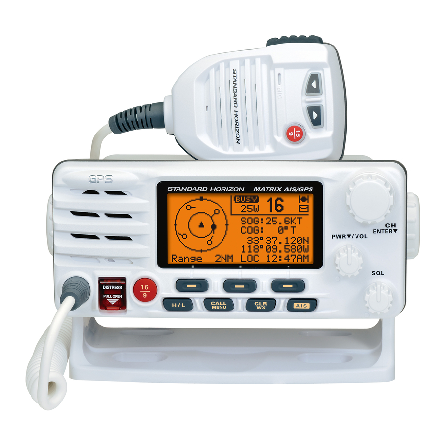
MATRIX AIS/GPS
GX2200
25 Watt VHF/FM
Marine Transceivers
Owner's Manual
Integrated 66 Channel GPS antenna
Integrated dual channel AIS (Automatic Identification System) receiver
AIS / AIS SART target display: MMSI, Call Sign, Ship Name, BRG, DST, SOG and COG
4800 or 38400 NMEA baud rate selection, for plotters with 1 NMEA port
True and Magnetic bearing selection on AIS display
Contact Class A or B AIS Ship with DSC
Programmable CPA or TCPA collision avoidance alarms
Meets ITU-R M493-13 Class D DSC (Digital Selective Calling)
Submersible IPX7 (3.3 feet or 1 meter for 30 minutes) front panel
80dB Commercial grade receiver
DSC position request and report functions
30 Watt PA/Loud Hailer with preprogrammed fog signals and listen back
ClearVoice noise canceling speaker microphone with channel selection and 16/9 key
GPS Compass, Waypoint and GPS status pages
Navigation (LAT/LON, Time, SOG and COG) information shown on display
Enter, Save and Navigate to waypoints with Compass page
E2O (Easy-To-Operate) menu system
User customizable soft keys for easy menu operation
Versatile user-programmable scanning, priority scan and Dual Watch
Oversized rotary channel knob with push to enter, backlit display and keys
Local/Distance attenuator
Optional connection for RAM3 second station remote microphone with AIS display
Intercom between radio and RAM3
Voice Scrambler (optional)
GX2200
Page 1
Advertisement
Table of Contents

Related Manuals for Standard Horizon GX2200


Summary of Contents for Standard Horizon GX2200
- Page 1 MATRIX AIS/GPS GX2200 25 Watt VHF/FM Marine Transceivers Owner's Manual Integrated 66 Channel GPS antenna Integrated dual channel AIS (Automatic Identification System) receiver AIS / AIS SART target display: MMSI, Call Sign, Ship Name, BRG, DST, SOG and COG 4800 or 38400 NMEA baud rate selection, for plotters with 1 NMEA port True and Magnetic bearing selection on AIS display Contact Class A or B AIS Ship with DSC Programmable CPA or TCPA collision avoidance alarms Meets ITU-R M493-13 Class D DSC (Digital Selective Calling) Submersible IPX7 (3.3 feet or 1 meter for 30 minutes) front panel 80dB Commercial grade receiver DSC position request and report functions 30 Watt PA/Loud Hailer with preprogrammed fog signals and listen back ClearVoice noise canceling speaker microphone with channel selection and 16/9 key GPS Compass, Waypoint and GPS status pages...
-
Page 2: Table Of Contents
8.11 PA/FOG OPERATION ..............43 9.13.3 Reviewing Other Logged Calls ........89 8.11.1 Operating the PA HAIL mode .........43 9.13.4 Deleting a Call from the DSC Log Directory ....89 8.11.2 Operating the FOG HORN mode ........44 10 GENERAL SETUP ................91 Page 2 GX2200... - Page 3 14.8 SELECTING THE WAYPOINT RANGE ........120 15 GPS SETUP ..................121 15.1 UNIT POWER ................121 15.2 COORDINATE SYSTEM............121 15.3 PINNING ..................122 15.4 TIME OFFSET .................122 15.5 TIME AREA ................122 15.6 TIME DISPLAY.................122 15.7 MAGNETIC ................123 15.8 POSITION INPUT ..............123 GX2200 Page 3...
-
Page 4: Quick Reference Guide
The GX2200 is equipped with the E2O (Easy-To-Operate) system. Basic operation may be accomplished by following the procedure below: Press and hold the PWR/VOL knob to turn on or off the radio. Rotate the PWR/VOL knob to adjust the speaker audio volume. Rotate the CH knob (or press the microphone’s keys) to select the operating channel. Move the SQL knob clockwise to squelch or counter clockwise to un-squelch the radio. ... -
Page 5: General Information
1 GENERAL INFORMATION The STANDARD HORIZON MATRIX Series GX2200 Marine VHF/FM Marine transceiver is designed to be used in USA, International, and Canadian Marine bands. The GX2200 can be operated from 11 to 16 VDC and has a switchable RF output power of 1 watt or 25 watts. The GX2200 integrates a dual channel AIS (Automatic Identification System) receiver to display AIS vessel information (MMSI, Call Sign, Ship Name, BRG, DST, SOG and COG) directly on the VHF radio, so you will know what is out there in any conditions. The GX2200 is also capable of entering... -
Page 6: Packing List
(in USA or Canada only) Please visit www.standardhorizon.com to register the GX2200 Marine VHF. It should be noted that visiting the website from time to time may be beneficial to you, as new products are released they will appear on the STANDARD HORIZON website. PRODUCT SUPPORT INQUIRIES If you have any questions or comments regarding the use of the GX2200, you can visit the STANDARD HORIZON website to send an E-Mail or contact the Product Support team at (800) 767-2450 M-F 8:00-5:00 PST. Page 6 GX2200... -
Page 7: Getting Started
In terms of effective radiated power (ERP), antennas are rated on the basis of how much gain they have over a theoretical antenna with zero gain. A 3-foot, 3dB gain antenna represents twice as much gain over the imaginary antenna. Typically a 3-foot 3dB gain stainless steel whip is used on a sailboat mast. The longer 8-foot 6dB fiberglass whip is primarily used on power boats that require the additional gain. GX2200 Page 7... -
Page 8: Coaxial Cable
CHANNEL 16. Then use the following proce- dure: 1. Press the microphone push-to-talk switch and say “Mayday, Mayday, Mayday. This is ” (your vessel’s name). 2. Then repeat once: “Mayday, ” (your vessel’s name). 3. Now report your position in latitude/longitude, or by giving a true or magnetic bearing (state which) to a well-known landmark such as a navi- gation aid or geographic feature such as an island or harbor entry. 4. Explain the nature of your distress (sinking, collision, aground, fire, heart attack, life-threatening injury, etc.). 5. State the kind of assistance your desire (pumps, medical aid, etc.). Page 8 GX2200... -
Page 9: Calling Another Vessel (Channel 16 Or 9)
10. If there is no answer, repeat the above procedure. If there is still no response, try another channel. NOTE The GX2200 has the DSC Distress calling, that can transmit a distress call digitally to all ships with compatible DSC radios. Refer to section “9 DIGITAL SELECTIVE CALLING (DSC)”. CALLING ANOTHER VESSEL (CHANNEL 16 OR 9) Channel 16 may be used for initial contact (hailing) with another vessel. -
Page 10: Making Telephone Calls
By regulation, power is normally limited to 1 Watt on these channels. Your radio is programmed to automatically reduce power to this limit on these channels. However, in certain situations it may be necessary to temporarily use a higher power. See Page 31 ( key) for means to temporarily H / L override the low-power limit on these two channels. Page 10 GX2200... -
Page 11: Automated Radio Check Service
The Automated Radio Check Service is currently available in the areas listed below. West Coast Sea Tow Newport/LA - Ch. 27 Sea Tow San Diego - Ch. 27 Northeast Sea Tow Portland-Midcoast (Maine) - Ch. 27 Sea Tow Boston - Ch. 27 Sea Tow South Shore (Mass.) - Ch. 28 Sea Tow Rhode Island - Ch. 24 Sea Tow Eastern Long Island - Ch. 27 Sea Tow Huntington (N.Y.) - Ch. 27 Sea Tow Manasquan (N.J.) - Ch. 28 Mid-Atlantic Sea Tow Northern Chesapeake (Md.) - Ch. 28 Sea Tow Central Chesapeake (Md.) - Ch. 27 Sea Tow Hampton Roads (Va.) - Ch. 28 North Carolina Sea Tow Wrightsville Beach - Ch. 28 Sea Tow Ocean Isle Beach - Ch. 28 Florida Sea Tow Sebastian - Ch. 28 Sea Tow Fort Lauderdale - Ch. 27 Sea Tow Charlotte Harbor - Ch. 24 Sea Tow Tampa Bay - Ch. 27 Sea Tow Horseshoe Beach - Ch. 27 Sea Tow Carrabelle/St. Marks - Ch. 27 Sea Tow Pensacola/Orange Beach (Ala.) - Ch. 27 GX2200 Page 11... -
Page 12: What Is The Range For Ais Receivers
Class B transponders use lower power for transmissions; therefore you can expect Class B vessels to be acquired when they are 5 to 10 miles away. NOTE The GX2200 does not require a special marine VHF antenna to receive AIS transmissions. The GX2200 does not transmit AIS signals, it is NOT recommended to use an antenna dedicated for AIS operation. For additional information on AIS visit the USCG website: <http://www.navcen.uscg.gov/marcomms/ais.htm> Page 12... -
Page 13: Installation
Antenna Installation: The antenna must be located at least 3 feet (1 m) away from passengers in order to comply with the FCC RF exposure requirements. LOCATION The radio can be mounted at any angle. Choose a mounting location that: • is far enough from any compass to avoid any deviation in compass reading due to the speaker magnet • provides accessibility to the front panel controls • allows connection to a power source and an antenna • has nearby space for installation of a microphone hanger • is at least 3 feet (1 m) away from the radio’s antenna • the signal from the GPS satellite can receive sufficiently. Note: To insure the radio does not affect the compass or radios performance is not affected by the antenna location, temporarily connect the radio in the desired location and: a. Examine the compass to see if the radio causes any deviation b. Connect the antenna and key the radio. Check to ensure the radio is operating correctly by requesting a radio check. GX2200 Page 13... -
Page 14: Mounting The Radio
MOUNTING THE RADIO 6.3.1 Supplied Mounting Bracket The supplied mounting bracket allows overhead or desktop mounting. Use a 13/64” (5.2 mm) bit to drill the holes to a surface which is more 0.4” (10 mm) thick and can support more than 3.3 lbs (1.5 kg) and secure the bracket with the supplied screws, spring washers, flat washers, and nuts. eSktop ounting verHeaD ounting Page 14 GX2200... -
Page 15: Optional Mmb-84 Flush Mount Bracket
Adjusting Screw Lock-washer screw combination NOTE A GPS receiver and antenna of the GX2200 is located in the front panel. In many cases the radio may be flush mounted, however before cutting holes to flush mount the radio it is recommended to temporarily connect the radio to power and turn on in the location where it will be flush mounted to confirm it is able to receive a GPS location on it’s display. If the radio is not able to receive a location, a... -
Page 16: Electrical Connections
When you replace the fuse, please confirm that the fuse is tightly fixed on the metal contact located inside the fuse holder. If the metal contact holding the fuse is loose, the fuse holder may heat up. Page 16 GX2200... -
Page 17: Accessory Cables
GPS and DSC information is transferred between a GPS chart plotter with multiple ports (minimum 2) at 4800 baud (default setting). To connect to a GPS chart plotter which has one NMEA port, the GX2200 may be setup to receive GPS coordinates, send DSC and AIS signals at 38400 baud. Refer to section “10.6 NMEA DATA IN/OUT” for details. -
Page 18: Internal Gps (Dsc Output) To Chart Plotter
*2: 38400 baud Note: Some GPS chart plotters have a single wire for NMEA signal ground. In such a case connect the NMEA input (–) to the GPS chart plotter’s single NMEA signal ground wire, and leave the NMEA output (–) open. In case the assignment of power supply and ground of a GPS chart plotter to be used is different from that of the radio, connect the signal ground wire of the GPS chart plotter to the ground terminal (GND) on the rear panel of the radio. Page 18 GX2200... - Page 19 No connection* *1: The GPS chart plotter ComPort must be setup to 38400 baud (HS) to receive DSC and AIS sentences from the GX2200 (Gray and Brown wires). *2: The GX2200 always outputs NMEA 0183 VDM sentence at 38400. Note: Some GPS chart plotters have a single wire for NMEA signal ground. In such a case connect the NMEA input (–) to the GPS chart plotter’s single NMEA signal ground wire, and leave the NMEA output (–) open. In case the assignment of power supply and ground of a GPS chart plotter to be used is different from that of the radio, connect the signal ground wire of the GPS chart plotter to the ground terminal (GND) on the rear panel of the radio.
-
Page 20: Connection To External Gps Or Chart Plotter
*2: 38400 baud Note: Some GPS chart plotters have a single wire for NMEA signal ground. In such a case connect the NMEA input (–) to the GPS chart plotter’s single NMEA signal ground wire, and leave the NMEA output (–) open. In case the assignment of power supply and ground of a GPS chart plotter to be used is different from that of the radio, connect the signal ground wire of the GPS chart plotter to the ground terminal (GND) on the rear panel of the radio. Page 20 GX2200... - Page 21 Shield of cable is not attached on PA Speaker end 2 conductor shielded Bare Connect the bare wire from the GX2200 PA Speaker to one wire and to the shielded. Make Red and bare connections short as possible GX2200...
- Page 22 External GPS Connections (4800 baud or 38400 baud) The GX2200 can select the NMEA baud rate between “4800 bps” and “38400 bps”. Refer to section “10.6 NMEA DATA IN/OUT” for selection. NMEA Input (GPS Information) • GX2200 can read NMEA-0183 version 2.0 or higher. • The NMEA 0183 input sentences are GLL, GGA, RMC, GNS, GSA, and GSV (RMC sentence is recommended). • If 4800 baud (default) is selected: a. If there is a selection for “PARITY” select “NONE”. b. The Blue and Green wires of input are at 4800 baud. • If 38400 baud is selected: The Blue and Green wires of input are at 38400 baud. NMEA Output (DSC and GPS information) • The NMEA 0183 output sentences are DSC and DSE. • If 4800 baud (default) is selected: a. The Gray and Brown wires output DSC and DSE sentences. b. The Yellow and White wires of output AIS VDM sentence at 38400 baud.
-
Page 23: Checking Gps Connections
NOTE When the GPS reception is limited, such as the flush mounting of the GX2200, the NMEA input (+) (blue) and NMEA input (-) (green) wires may be connected to the NMEA output connections of an external GPS antenna or a GPS chart plotter. To change the GX2200 from using the internal GPS antenna to the external GPS antenna, refer to section “15.9 POSITION DATA PRIORITY” (for selection), and “15.1 UNIT POWER” (for turning off). For further information on interfacing/setting up your GPS, please contact the manufacturer of the GPS receiver externally connected. If you have further inquires, please feel free to contact Product Support at: Phone: (800) 767-2450 Email: marinetech@yaesu.com CHECKING GPS CONNECTIONS... -
Page 24: Changing The Gps Time
NOTE When the GX2200 is first turned on, it may take several minutes to compute a fix of your position. This is normal, as the GX2200 is downloading “almanac” information from the GPS satellites. CHANGING THE GPS TIME From the factory the GX2200 shows GPS satellite time or UTC (Universal Time Coordinated) time. A time offset is needed to show the local time in... -
Page 25: Changing The Time Location
TIME AREA ”. 3. Press the soft key. 4. Rotate the CH knob to select “ UTC ” or “ LOCAL ”. 5. Press the soft key to store the selected -Time Area- setting. Local 6. Press the soft key two times to return to radio operation. QUIT GX2200 Page 25... -
Page 26: Changing The Time Format
4. Rotate the CH knob to select “ M A G N E T I C ” or “ TRUE ”. -Magnetic- 5. Press the soft key to store the selected TRUE Magnetic setting. 6. Press the soft key two times to return to QUIT radio operation. NOTE Setting to “Magnetic” is effective only when the RMC sentences with magnetic data are input from external devices such as a GPS receiv- er. It is ineffective when using the internal GPS of the GX2200. Page 26 GX2200... -
Page 27: Optional Cmp30 ( Ram3 ) Installation
6.11 OPTIONAL CMP30 ( RAM3 ) INSTALLATION The GX2200 is capable of using a CMP30 ( RAM3 ) Remote Station Micro- phone to remotely control the Radio, AIS, DSC and PA/Fog functions. In addition the GX2200 can operate as a full function intercom system between the CMP30 ( RAM3 ) and the GX2200. - Page 28 Gasket Wall Routing Cable Mounting Bracket NOTE Caution!: Before cutting the cable, it must be disconnected from the rear panel of the transceiver. The routing cable can be cut and spliced, however care needs to be taken when reconnecting the wires to ensure water integrity. After cutting you will notice there are the following wires: Yellow, White, Brown, Gray, Blue, Green, Red/White , Shield The red/white and shield wires are wrapped in foil. Remove the foil, and separate the red/white and shield wires. WARNING It is not recommended to plug or unplug the CMP30 ( RAM3 ) Remote Station Microphone into the routing cable while the radio is on. Page 28 GX2200...
-
Page 29: Connecting An External Speaker To The Ram3 Mic Cable
SETUP ” with the key. 2. Press the key. 3. Press the key to until “ AF SELECT ” is shown and press the soft key. 4. Press the key to select “ PRE-OUT ” (exter- nal speaker level is “Fixed”) or “ PA-OUT ” (external speaker level is “Adjustable”). Use “Fixed” when MLS-310 is connected. Use “Adjustable” when MLS-300 or other speaker without volume control is connected. 5. Press the soft key to save the selection. 6. Press the key to exit this mode. GX2200 Page 29... -
Page 30: Controls And Indicators
When in the PA or Fog mode, turning this knob changes the output volume of the connected horn speaker. PWR/VOL Knob ( Power Switch / Volume Control ) Turns the transceiver on and off as well as adjusts the speaker volume. To turn the transceiver on, press and hold this knob until the radio turns When the power is turned on, the transceiver is set to the last selected channel. Clockwise rotation of this knob increases the internal and speaker microphone volume. To turn the transceiver off, press and hold this knob until the radio turns off. Page 30 GX2200... - Page 31 H / L Press the key to toggle between 25 W (High) and 1 W (Low) H / L power. When the TX output power is set to “Low” while the transceiver is on channel 13 or 67, the output power will temporarily switch from “Low” to “High” power until the PTT switch of the microphone is released. The key does not function on transmit inhibited and low power only H / L channels. GX2200 Page 31...
-
Page 32: Rear Panel
ANT Jack ( Antenna Jack ) Connects an antenna to the transceiver. Use a marine VHF antenna with an impedance of 50 ohms. Note: On the GX2200 the antenna connection is used to receive marine and AIS receiver. GND Terminal ( Ground Terminal ) Connects the GX2200 to a good ground, for safe and optimum perfor- mance. Use the screw supplied with the GX2200 only. E xternal Speaker Connection Cable ( White & Shield ) Connects the GX2200 to an external speaker. See section “3 OPTIONAL ACCESSORIES” for a list of optional STANDARD HORIZON Speakers. Page 32... -
Page 33: Microphone
Connects the GX2200 to a GPS chart plotter. Refer to section “6.5 ACCESSORY CABLES”. RAM3 Connector ( Remote Station Microphone Connector ) Connects the GX2200 to the CMP30 ( RAM3 ) Remote Station Micro- phone. Refer to section “16 CMP30 ( RAM3 ) REMOTE MIC OPERA- TION” for details. - Page 34 Audio heard through internal radio speaker is heard through speaker inside the microphone. Keys (DOWN/UP Keys) keys on the microphone are used to select channels and to choose menu items (such as the DSC menu, General Setup and DSC Setup menus). Key Pressing the key immediately recalls Channel 16 from any location. Press and hold the key to recall Channel 9. Pressing the key again will revert the radio to the previous selected channel. Page 34 GX2200...
-
Page 35: Basic Operation
This is a noise-canceling microphone. Position the oval slot labeled “MIC” within 1/2” (1.5 cm) from the mouth for optimum performance. TRANSMIT TIME - OUT TIMER (TOT) When the PTT switch on the microphone is held down, transmit time is limit- ed to 5 minutes. This limits unintentional transmissions due to a stuck micro- phone. About 10 seconds before automatic transmitter shutdown, a warning beep will be heard from the speaker(s). The transceiver will automatically go to receive mode, even if the PTT switch is continually held down. Before transmitting again, the PTT switch must first be released and then pressed again. GX2200 Page 35... -
Page 36: Simplex/Duplex Channel Use
NOTE All channels are factory-programmed in accordance with FCC (USA), Industry Canada (Canada), and International regulations. Mode of operation cannot be altered from simplex to duplex or vice-versa. DISPLAY TYPE The GX2200 display can be setup to show displays other than the default “NORMAL” VHF display by using the procedure below: 1. Press and hold the key until “ Setup Menu ” CALL MENU appears, then select “ GENERAL SETUP ” with the CH knob. -
Page 37: Usa, International, And Canada Mode
3. To exit from the NOAA weather channels, press and hold the key. The transceiver returns to the channel it was on prior to a weather channel and the “WX” icon disappears from the display. 8.7.1 NOAA Weather Alert In the event of extreme weather disturbances, such as storms and hurri- canes, the NOAA (National Oceanic and Atmospheric Administration) sends a weather alert accompanied by a 1050 Hz tone and subsequent weather report on one of the NOAA weather channels. The GX2200 can receive weather alerts when on a weather channel and on the last selected weather channel during scanning modes or while on anoth- er channel. GX2200 Page 37... -
Page 38: Noaa Weather Alert Testing
ALERT”. NOTE If the key is not pressed the alert will sound for 5 minutes and then the weather report will be received. 8.7.2 NOAA Weather Alert Testing NOAA tests the alert system ever Wednesday between 11AM and 1PM. To test the GX2200’s NOAA weather feature, on Wednesday between 11AM and 1PM, setup as in section “8.7.1 NOAA Weather Alert” and confirm the alert is heard. DUAL WATCH (TO CHANNEL 16) Dual watch is used to scan two channels for communications. One channel is a normal VHF channel and the other is the priority, Channel 16. When a signal is received on the normal channel the radio briefly switches between the normal channel and Channel 16 to look for a transmission. If the radio receives communications on Channel 16 the radio stops and listens to Chan- nel 16 until communication ends and then starts dual watch scan again. -
Page 39: Scanning
NOTE The priority channel may be changed from CH16 to another channel. Refer to section “11.5 PRIORITY CHANNEL”. SCANNING The GX2200 will automatically scan channels programmed into the preset channel memory and also the scan channel memory, and the last selected weather channel. When an incoming signal is detected on one of the channels during scan, the radio will pause on that channel, allowing you to listen to the incoming trans- mission. The radio will automatically start scanning again after the transmis- sion stops. 8.9.1 Selecting the Scan Type 1. Press and hold the key until “... -
Page 40: Programming Scan Memory
8.9.3 Memory Scanning (M-SCAN) 1. Adjust the SQL knob until background noise disappears. 2. Press one of the soft key, then press the soft key. “ M-SCAN ” appears on the display. Scan- ning will proceed from the lowest to the highest programmed channel number and preset channel (described in the next section) and will stop on a channel when a transmission is received. The channel number will blink during reception. 3. To stop scanning, press the key. Page 40 GX2200... -
Page 41: Priority Scanning (P-Scan)
33 37.120 118 09.580 program. QUIT 25W USA 4. Press the soft key to program the channel SET 1: 06 SOG:25.0 into the preset channel. COG:123 33 37.120 118 09.580 12:56 SAFETY 5. Repeat steps 1 through 4 to program the desired channels into the preset channels “0” ~ “9”. GX2200 Page 41... -
Page 42: Operation
SOG:25.0 PRESET COG:123 blinking. 33 37.120 118 09.580 4. Press the soft key to delete the channel DELETE QUIT from the preset channel. 5. Repeat steps 2 through 4 to delete the desired channels from preset channels “0” ~ “9”. 6. To exit from deleting the preset channels, press the soft key. Page 42 GX2200... -
Page 43: Pa/Fog Operation
NOTE When in the PA HAIL or FOG HORN mode, the GX2200 will continue to receive DSC calls and communications on the last selected work- ing channel prior to entering the PA HAIL or FOG HORN mode. Then the GX2200 AIS page can also be accessed when in the PA HAIL or FOG HORN mode. PA HAIL mode: PA HAIL mode allows the transceiver to be used as a power hailer when an optional STANDARD HORIZON 220SW or 240SW HAIL/PA horn is installed. The PA Hail mode has a listen-back feature which provides two way communication through the HAIL/PA horn. FOG HORN mode: Automatic signaling is transmitted through the HAIL/PA horn. When the... -
Page 44: Operating The Fog Horn Mode
5. On the “ Horn ” and “ Siren ” modes, press the PTT switch to activate the tone through the HAIL/PA speaker. Rotate the CH knob to control the AF output level. The AF output level can be set from 0 to 30 watts. 6. To listen back, rotate the PWR/VOL knob. 7. To exit the FOG HORN mode, press the key. NOTE When in the FOG HORN mode it is possible to simultaneously use the AIS page by pressing the key. Page 44 GX2200... -
Page 45: Fog Signal Timing Chart
Listen Back a vessel towing or pushing another ahead. 120s One 5-second blasts followed by three Vessel under tow (manned). 1-second blasts (separated by 2 seconds) every 120 seconds. Listen Back 120s AGROUND One 11-second rings every 60 seconds. Vessel is aground. 250ms Listen Back ANCHOR One 5-second rings every 60 seconds. Vessel is at anchor. 250ms 5.25s Listen Back GX2200 Page 45... -
Page 46: Intercom Operation
8.12 INTERCOM OPERATION To access the following intercom functions one of the soft keys must be setup as “IC”. Refer to section “10.10 SOFT KEYS”. In addition an optional RAM3 remote station microphone (e.g. CMP30) must be connected to perform intercom functions between the GX2200 and the RAM3. 8.12.1 Communication 1. Press one of the soft keys, then press the soft key to enable the intercom mode. Note: Depending on the programming of the... -
Page 47: Voice Scrambler
If privacy of communications is desired, a CVS2500A 4-code voice scram- bler (VS) can be installed in the transceiver. Contact your Dealer to have a CVS2500A installed. Refer to the section “11.8 SCRAMBLER SETUP” to program the voice scrambler. 1. Select a channel that was programmed for scrambler mode (“ Vs ” and scrambler number will appear on the display). 2. Monitor the channel before transmitting. 3. Transmit the voice message. The signal sent will be scrambled. GX2200 Page 47... -
Page 48: Demo Mode
6. To store the data entered, press and hold soft key. 7. Rotate the CH knob to “ DEMO START ” and press the soft key. 8. Select “ S T A R T ” using the CH knob and press the soft key. NOTE To stop the demo mode, select “ STOP ” in step 8 above. Page 48 GX2200... -
Page 49: Digital Selective Calling (Dsc)
NOTE A DSC Warning sticker is included with WARNING STICKER the GX2200. To comply with FCC regu- lations this sticker must be mounted in a location that can be easily viewed from the location of the GX2200. Digital Selective Calling (DSC) is a semi-automated method of establishing a radio call, it has been designated by the International Maritime Organization (IMO) as an international standard for establishing VHF, MF and HF radio calls. It has also been designated as part of the Global Maritime Distress and... -
Page 50: Programming The Mmsi
7. When finished programming the MMSI -User MMSI- Input User MMSI BACK QUIT number, press and hold the soft key. ********* The radio will ask you to input the MMSI Input Again 123456789 number again. Use steps 4 through 6 BACK QUIT above. Page 50 GX2200... -
Page 51: Dsc Distress Call
NOTE To view your MMSI after programming to ensure it is correct, perform steps 1 to 3. Look that the MMSI number shown on the display is correct. DSC DISTRESS CALL The GX2200 is capable of transmitting and receiving DSC distress messag- es to all DSC radios. The GX2200 may be connected to a GPS to also trans- mit the latitude and longitude of the vessel. 9.3.1 Transmitting a DSC Distress Call NOTE To be able to transmit a DSC distress call an MMSI number must be programmed, refer to section “9.2.2 Programming the MMSI.” In order for your ships location to be transmitted, the internal GPS must be able to receive a fix or a optional GPS antenna or chart plotter must be connected. Refer to section “6.5 ACCESSORY CABLES.”... - Page 52 6. To turn off the distress alarm before the radio retransmits the distress call, press the key. Transmitting a DSC Distress Alert with Nature of Distress The GX2200 is capable of transmitting a DSC distress alert with the following “Nature of Distress” categories: Undesignated, Fire, Flooding, Collision, Grounding, Capsizing, Sinking, Adrift, Abandoning, Piracy, MOB 1. Press the key. The “ D S C M e n u ” will...
- Page 53 Transmitting a DSC Distress Alert with Manual Position of Input When the GX2200 is not connected to a GPS receiver, you may input the latitude and longitude of your vessel manually before you send a DSC distress alert. 1. Press the key. The “...
-
Page 54: Receiving A Dsc Distress Call
Canceling a DSC Distress Call If a DSC distress call was sent by error the GX2200 allows you to send a message to other vessels to cancel the distress call that was made. Press the soft key, then press the soft key. !DISTRESS ALERT! Nature of:Undesignated Position: 33 37.120 118 09.580 POS Time: 10:00 TX in: 02:25... - Page 55 6. To stop navigating to a waypoint, press one of the soft keys, then press the soft key. The radio is switched to the normal mode. NOTE You must continue monitoring Channel 16 as a coast station may require assistance in the rescue attempt. NOTE When there is an unread distress alert, “ ” icon will appear on the display. You may review the unread distress alert from the DSC log, refer to the section “9.13.2 Reviewing a Logged DSC Distress Call.” GX2200 Page 55...
-
Page 56: All Ships Call
8. Listen to the channel to make sure it is not CH: 06 Transmiting busy, then key the microphone and say “PAN PAN, PAN PAN, PAN PAN” or “Securite, -All Ships Call- Securite, Securite” depending on the prior- Category:Safety CH: 06 ity of the call. Since: 00:25 9. Press the soft key to exit the all QUIT ships call menu. Page 56 GX2200... -
Page 57: Receiving An All Ships Call
: Press this key to temporarily disable automatic switching to the requested channel. Note: In some cases automatically switching to a requested chan- nel might disrupt import ongoing communications. This feature allows commercial users to suspend channel switching and stay on the working channel selected before the all ships call was received. : Press this key to quit the automatic channel switching and revert to the last selected working channel. 4. Press the key to return to the channel display. NOTE When there is an unread all ships call, “ ” icon will appear on the display. You may review the unread all ships call from the DSC log, refer to the section “9.13.3 Reviewing Other Logged Calls.” GX2200 Page 57... -
Page 58: Individual Call
9.5.1 Setting up the Individual / Position Call Directory The GX2200 has a DSC directory that allows you to store a vessel or person’s name and the MMSI (Maritime Mobile Service Identity Number) number associated with vessels you wish to transmit individual calls, auto polling, position request, position report, and polling transmissions. -
Page 59: Setting Up The Individual Call Reply
Individual Ring Group Directory -Individual Reply- 5. Rotate the CH knob to select “ AUTOMATIC ” Position Reply AUTOMATIC SELECT Manual QUIT or “ MANUAL ”. 6. Press the soft key to store the QUIT selected setting. 7. Press the soft key two times to return to radio operation. GX2200 Page 59... -
Page 60: Enabling The Individual Call Acknowledgment
4. Rotate the CH knob to select an individual you want to contact. Press the soft key to select an indi- vidual other than those on the display. 5. Press the soft key, then rotate the CH knob to select the operating channel you want to communicate on, then press soft key. 6. Press the soft key to transmit the individual DSC signal. Page 60 GX2200... - Page 61 Name: ID:345678901 10. Press the soft key to transmit the Category:Routine CH: 08 individual DSC signal. Transmit? QUIT 11. When an individual call acknowledgment is received, the established channel is automatically changed to the channel which is selected on step 9 above and a ringing tone sounds. GX2200 Page 61...
-
Page 62: Receiving An Individual Call
3. Press the microphone’s PTT switch and talk into the microphone to the other vessel. 4. Press the soft key to return to radio operation. Manual reply: 1. When an individual call is received, an individual call ringing alarm sounds. The display shows the MMSI of the vessel trans- mitting the individual call and the radio will change to the requested channel after 10 seconds. 2. Press any key to stop the alarm. 3. Monitor the requested channel until the message is completed. On the display you will notice 3 soft key selec- tions. These selections are described below: : Press this key to accept the DSC individ- ual call and to switch to requested channel. Note: If a key is not pressed for 30 seconds or longer the radio will auto- matically change to the requested channel. Page 62 GX2200... -
Page 63: Setting Up The Individual Call Ringer
Individual Reply Individual Ack 4. Press the soft key. INDIVIDUAL RING Group Directory 5. Rotate the CH knob to select ringing time of Position Reply SELECT QUIT individual calls. 6. Press the soft key to store the selected setting. soft key two times to 7. Press the return to radio operation. GX2200 Page 63... - Page 64 The GX2200 has the capability to turn off the individual call ringer. 1. Press and hold the key until “ Setup CALL MENU Menu ” appears. 2. Rotate the CH knob to select “ DSC SETUP ” menu. 3. Press the soft key, then select “ DSC BEEP ” with the CH knob. 4. Press the soft key. 5. Rotate the CH knob to select “ Individual ”, -DSC Beep- then press the soft key. Select Call Individual 6. Rotate the CH knob to select “ Off ”.
-
Page 65: Group Call
MMSI so they can be contacted by each other. There is a chance that another group of vessels may program in the same group MMSI. If this happens, simply change one or more of the last 5 digits of the group MMSI. GX2200 Page 65... - Page 66 BACK also be used to enter a blank space in the name. If a mistake was made entering in the name repeat pressing the soft key until the wrong character is selected, then rotate the CH knob to correct the entry. 9. After the eleventh letter or space has been entered, press and hold the soft key to advance to the group MMSI number entry. 10. Rotate the CH knob to select the second number of the MMSI (nine digits: first digit permanently set to “0”) which you want to contact, then press the soft key to step to the next number. Repeat this proce- dure until all eight spaces of the MMSI number are entered. If a mistake was made entering in the MMSI number repeat pressing the soft key until the wrong number is selected, then rotate the CH knob to correct the entry. soft key. 11. To store the data entered, press and hold the 12. To enter another group address, repeat steps 5 through 11. 13. Press the soft key three times to return to radio operation. Page 66 GX2200...
-
Page 67: Transmitting A Group Call
6. Press the soft key to transmit the group call signal. 7. When the group call signal is sent, the display will be as shown in the illustration at the right. 8. After the group call is transmitted, all the radios in the group will switch to the desig- nated channel. 9. Listen to the channel to make sure it is not busy, then press the micro- phone’s PTT switch and call the other vessel you desire to communicate with. GX2200 Page 67... - Page 68 8. When finished entering the MMSI number, ID:034567891 Category:Routine CH: 08 press and hold the soft key. Since: 00:25 9. Rotate the CH knob to select the operating QUIT channel you want to communicate on, then press the soft key. 10. Press the soft key to transmit the group call signal. 11. After the group call is transmitted, all the radios in the group will switch to the designated channel. 12. Listen to the channel to make sure it is not busy, then press the PTT switch and talk into the microphone to the group of vessels. Page 68 GX2200...
-
Page 69: Receiving A Group Call
9.6.3 Receiving a Group Call 1. When a group call is received, the GX2200 will produce a ringing alarm sound. 2. The display shows the group MMSI number. 3. Press any key to stop the alarm. 4. Monitor the channel for the person calling the group for a message. On the display you will notice 3 soft key selections. These selections are described below: : Press this key to accept the group call and to switch to request- ed channel. Note: If a key is not pressed for 30 seconds or longer the radio will auto- matically change to the requested channel. : Press this key to temporarily disable automatic switching to the requested channel. : Press this key to quit the automatic channel switching and revert to the last selected working channel. 5. If you want to respond, monitor the channel to make sure it is clear, then press the microphone’s... -
Page 70: Setting Up The Group Call Ringer
9.6.4 Setting up the Group Call Ringer The GX2200 has the capability to turn off the group call ringer. 1. Press and hold the key until “ Setup CALL MENU Menu ” appears. 2. Rotate the CH knob to select “ DSC SETUP ” menu. 3. Press the soft key, then select “ DSC BEEP ” with the CH knob. 4. Press the soft key. 5. Rotate the CH knob to select “ Group ”, then press the soft key. -
Page 71: Position Request
POSITION REQUEST Advancements in DSC have made it possible to poll the location of another vessel and show the position of that vessel on the display of the GX2200. Standard Horizon has taken this feature one step further, if any compat- ible GPS chart plotter is connected to the GX2200, the polled position of the vessel is shown on the display of the GPS chart plotter making it easy to navigate to the location of the polled vessel. This is a great feature for... -
Page 72: Transmitting A Position Request To Another Vessel
NMEA DSC and DSE sentences. 6. Press the soft key to return to radio operation. NOTE If the GX2200 does not receive a position data from the polled vessel, the display will show “NO POSITION DATA.” Position Request by Manually Entering an MMSI This feature allows you to request the position of a vessel by manually enter- ing the MMSI of the ship you want to ask the position. 1. Press the key. The “ DSC Menu ” will... -
Page 73: Receiving A Position Request
8. Press the soft key to transmit the Transmit? position request DSC call. QUIT 9. When the GX2200 receives the position from the polled vessel it is shown on the radio display and also transferred to the GPS chart plotter with NMEA DSC and DSE sentences. -
Page 74: Setting Up A Position Request Ringer
Or to exit from position REPLY Category:Routine request display, press the soft key. Since: 01:03 Transmitted QUIT 9.7.4 Setting up a Position Request Ringer The GX2200 has the capability to turn off the position request ringer. 1. Press and hold the key until “ Setup CALL MENU Menu ” appears. 2. Rotate the CH knob to select “ DSC SETUP ” menu. 3. Press the soft key, then select “... -
Page 75: Position Report
Your vessel must mark the internal GPS receiver for the GX2200 to send the position. NOTE To transmit a position report call, the GX2200 individual directory must be programmed with stations you wish to send your position to. To setup this directory refer to section “9.5.1 Setting up the Indi- vidual / Position Call Directory.”... -
Page 76: Receiving A Dsc Position Report Call
8. Press the soft key to send your position to the selected vessel. 9. Press the soft key to return to radio operation. 9.8.2 Receiving a DSC Position Report Call When another vessel transmits their vessels location to the GX2200 the following will happen: 1. A ringing sound will be produced when the call is Received POS REPORT Name:Horizon received and NMEA sentences (DSC, DSE) are ID:123456789... -
Page 77: Navigating To A Position Report
2. Press the key. The radio will stop navigat- ing to a the waypoint and the Normal VHF display will be shown. 9.8.5 Saving a Position Report as a Waypoint The GX2200 can save a position report call in the radio’s memory as a waypoint. 1. After the position report call has been Received POS REPORT Name:Horizon received, press the soft key. -
Page 78: Navigating To A Saved Waypoint
SELECT QUIT Position: 33 33.120 The display indicates the distance and 118 06.230 QUIT direction of the saved waypoint, and also the compass indicates the saved waypoint by dot ( ) . To stop the navigation to a saved waypoint, perform the steps 1 to 5 above, except selecting “ NORMAL ” in the step 5. Page 78 GX2200... -
Page 79: Setting Up A Position Report Ringer
9.8.7 Setting up a Position Report Ringer The GX2200 has the capability to turn off the position report ringer. 1. Press and hold the key until “ Setup CALL MENU Menu ” appears. 2. Rotate the CH knob to select “ DSC SETUP ” menu. 3. Press the soft key, then select “ DSC BEEP ” with the CH knob. 4. Press the soft key, then select “ POS Report ” with the CH knob. 5. Press the soft key, then select “... -
Page 80: Manual Input Of A Gps Location (Lat/Lon)
MANUAL INPUT OF A GPS LOCATION (LAT/LON) You may send the latitude and longitude of your vessel manually even if the GX2200 is located in an area where GPS reception is limited. After the position is entered, transmitting a DSC distress, position request, or position report will contain the manually entered position. 1. Press and hold the key until “ Setup CALL MENU Menu ” appears. 2. Rotate the CH knob to select “ GPS SETUP ” menu. 3. Press the soft key, then select “ POSITION INPUT ” with the CH knob. 4. Press the soft key. The transceiver... -
Page 81: Auto Pos Polling
9.10 AUTO POS POLLING The GX2200 has the capability to automatically track four stations programmed into the individual directory. The following procedure allows the time interval between position requests to be setup. 9.10.1 Setting up the Polling Time Interval 1. Press and hold the key until “ Setup CALL MENU Menu ” appears. -
Page 82: Enabling/Disabling Auto Pos Polling
“ STOP ” to disable transmis- Select Address sions to stations. -Auto POS Polling- START 5. Press the soft key. QUIT SELECT Stop 6. Press the soft key two times to return to radio operation. QUIT NOTE When the radio receives position reports from a called vessel the display will show the image as in the right and also output NMEA 0183 DSC and DSE sentences to a GPS chart plotter. Page 82 GX2200... -
Page 83: Dsc Test
3. Rotate the CH knob to select the ship name and press the soft key. 4. Press the soft key to transmit the DSC test call to the other vessel. 5. Press the soft key to return to radio operation. NOTE After the radio receives a test call reply from the vessel that was called, the radio will ring and show “TEST ACK” display, which confirms the radio you called received the test call. GX2200 Page 83... -
Page 84: Dsc Test Call By Manually Entering An Mmsi
SELECT BACK QUIT 8. Press the soft key to return to radio operation. NOTE After the radio receives a test call reply from Received TEST ACK Name: the vessel that was called, the radio will ring ID:345678901 Category:Routine and show “TEST ACK” display, which confirms Since: 00:25 the radio you called received the test call. QUIT Page 84 GX2200... -
Page 85: Polling Call
9.12 POLLING CALL The GX2200 has the capability to track another vessel. 9.12.1 Transmitting a Polling Call to Another Vessel Polling Call using the Individual/Position Call Directory 1. Press the key. The “ DSC Menu ” will CALL MENU appear. 2. Rotate the CH knob to select “ POLLING ”, then press the soft key. -
Page 86: Receiving A Polling Call
7. When finished entering the MMSI number, press and hold the soft key. 8. Press the soft key to transmit the polling call. 9. Press the soft key to return to radio operation. 9.12.2 Receiving a Polling Call When another vessel transmits a polling call to the GX2200 the following will happen: 1. When a polling call is received, the radio will auto- matically respond to the calling vessel. 2. To exit from the polling call display, press the soft key. Page 86 GX2200... -
Page 87: Dsc Log Operation
“ ” icon will appear on the radios display. The GX2200 can store up to 24 transmitted calls, up to the latest 27 distress calls, and up to the latest 64 other calls (individual, group, all ships, position report, position request ack, test call ack, and polling calls). -
Page 88: Reviewing A Logged Dsc Distress Call
9.13.2 Reviewing a Logged DSC Distress Call The GX2200 allows logged DSC distress call to be reviewed. 1. Press the key. The “ D S C M e n u ” will CALL MENU appear. 2. Rotate the CH knob to select “ DSC LOG ” menu. 3. Press the soft key, then rotate the CH knob to select “... -
Page 89: Reviewing Other Logged Calls
CH knob to select “ ALL LOG DELETE ” or SELECT QUIT “ VIEW LOG LIST ”. -Distress Log- ALL LOG DELETE 1) If you want to delete all stations at a time, View Log List select the “ ALL LOG DELETE ” with the CH knob, press the soft key. SELECT QUIT GX2200 Page 89... - Page 90 Rotate the CH knob to select the station ( n a m e o r M M S I number) to be delet- ed, then press the soft key. 3) The display will show “ Are you sure? ”. Press the soft key. 6. Press the soft key six times to return to radio operation. Page 90 GX2200...
-
Page 91: General Setup
10 GENERAL SETUP The optional CMP30 ( RAM3 ) Remote Station Microphone can also change the setup menu using the following procedure. 10.1 DISPLAY The GX2200 can select additional screens other than the default normal (radio) display. Refer to section “8.5 DISPLAY TYPE” for details. 10.2 LOCAL DISTANCE RECEIVER ATTENUATOR In some areas, signals from external sources may cause interference to receiving marine transmissions. The GX2200 has two selections, “Distance” -... -
Page 92: Dimmer Adjustment
4. Press the soft key. 5. Rotate the CHANNEL selector knob to select the -Contrast- desired level. The contrast level can be set from “ 0 ” to “ 31 ” (“ 15 ” is default). 6. Press the soft key to store the selected QUIT level. 7. Press the soft key two times to return to radio operation. Page 92 GX2200... -
Page 93: Unit Of Measure
KTS (knots), MPH (mile/hour), or KMH (kilo- SELECT QUIT -Speed Unit- meter/hour) for speed, NM (nautical mile), SM KTS:KNOTS MPH:Mile/Hour (statute mile) or KM (kilometer) for distance, and KMH:Kilo-Meter/Hour FT (feet) or M (meter) for altitude. QUIT 7. Press the soft key to store the selected level. 8. Press the soft key three times to return to radio operation. GX2200 Page 93... -
Page 94: Nmea Data In/Out
“ LEVEL 6 ”, “ HIGH ”, or “ OFF ”. Level 5 Level 4 6. Press the soft key to store the selected Level 3 Level 2 level. QUIT 7. Press the soft key two times to return to radio operation. Page 94 GX2200... -
Page 95: Fog Alert Tone Frequency
5. Rotate the CH knob to select the desired tone frequency. 6. Press the soft key to store the selected level. 7. Press the soft key two times to return to radio operation. NOTE By default the radio Fog frequency is set to 400Hz. In most cases this frequency should not be changed unless the vessel is very large. GX2200 Page 95... -
Page 96: Station Name
This method can also be used to enter a blank space in the name. If a mistake was made entering in the name repeatedly press the soft key until the wrong character is selected, then rotate the CH knob to correct the entry. 9. Press and hold the soft key to enter the name. 10. If you want to enter the name of the other connected RAM3 or radio, repeat steps 5 through 9. 11. Press the soft key three times to return to radio operation. Page 96 GX2200... -
Page 97: Soft Keys
10. Press the key, then rotate the CH knob to select “ KEY TIMER ” (selects how long the soft key icon will be shown on the display after a soft key is pressed; default is 5 seconds). Then, press the soft key. 11. Rotate the CH knob to select the time. 12. Press the soft key to store the selected setting. 13. Press the soft key three times to return to radio operation. GX2200 Page 97... - Page 98 DISPLAY FUNCTION DIMMER Select the menu for the display and key back light intensity SCAN Starts and stops scanning. Starts and stops dual watch scan. Activates intercom between radio and RAM3 mic (optional RAM3 required). PA/FOG Activates the PA / Fog Horn function. CPS: COMPASS Shows the “Compass” display. Shows the “Waypoint” navigation display. Shows the “AIS” display. AIS AL Toggles the AIS alarm “on” and “off”. PRESET Porgrams or deletes the preset memory channel. MARK Mark the current position for a “Waypoint”. PSET 0 - PSET 9 Immediately recalls the preset memory channel. Page 98 GX2200...
-
Page 99: Channel Function Setup
To be able to scan channels the radio must be programmed. This section allows channels to be stored in scan memory. Refer to section “8.9.2 Programming Scan Memory” for details. 11.3 SCAN TYPE This selection is used to select the scan mode between “Memory Scan” and “Priority Scan”. The default setting is “Priority Scan”. Refer to section “8.9.1 Selecting the Scan Type” for details. 11.4 SCAN RESUME This selection is used to select the time the GX2200 waits after a transmis- sion ends before the radio start to scan channels again. The default setting is 2 seconds. 1. Press and hold the key until “ Setup Menu ” CALL MENU appears. -
Page 100: Priority Channel
3. Press the soft key, then select “ PRIORITY CH ” with the CH knob. 4. Press the soft key. 5. Rotate the CH knob to select the desired channel to be a priority. 6. Press the soft key to store the new setting. 7. Press the soft key two times to return to -Priority CH- radio operation. QUIT Page 100 GX2200... -
Page 101: Weather Alert
When the radio (“Normal”) mode is selected, the display will show a name under the channel number. This name describes the use of the channel. The radio has the capability to customize the name by the procedure below. Example: CH69 PLEASURE to HOOKUP 1. Press and hold the key until “ Setup Menu ” CALL MENU appears. 2. Rotate the CH knob to select “ CH FUNCTION SETUP ”. 3. Press the soft key, then select “ CH NAME ” with the CH knob. 4. Press the soft key. GX2200 Page 101... - Page 102 CH knob to correct the entry. 9. Press and hold the soft key to save the name. 10. If you want to enter the name of another channel, repeat the steps 5 through 9. 11. Press the soft key three times to return to radio operation. Page 102 GX2200...
-
Page 103: Scrambler Setup
5. Rotate the CH knob to select the channel to be scrambled and press the soft key. 6. Rotate the CH knob to select the scrambler code. The scrambler code can be set from “ 0 ” to “ 3 ” and “ Off ”. When “ Off ” is selected the voice scrambler is disabled. 7. Press the soft key to store the selected code. 8. Repeat steps 5 through 7 to set other channels. 9. Press the soft key three times to return to radio operation. GX2200 Page 103... -
Page 104: Dsc Setup
12 DSC SETUP 12.1 INDIVIDUAL DIRECTORY The GX2200 has a DSC directory that allows you to store a vessel or person’s name and the MMSI number associated with vessels you wish to transmit individual calls, position requests and position report transmissions. To transmit an individual call you must program this directory with information of the persons you wish to call, similar to a cellular phones telephone directory. Refer to section “9.5.1 Setting up the Individual / Position Call Directory”... -
Page 105: Position Reply
12.6 POSITION REPLY The GX2200 can be set up to automatically (default setting) or manually send your position when requested by another vessel. This selection is important if you are concerned about someone polling the position of your vessel that you may not want to. In the manual mode you will see the MMSI or persons name shown on the display allowing you to choose to send your position to the requesting vessel. -
Page 106: Auto Channel Switch Time
12.9 AUTO CHANNEL SWITCH TIME When a DSC distress or an all ships (urgency or safety) call is received, the GX2200 will automatically switch to Channel 16. This menu selection allows the automatic switch time to be changed. The default selection is 30 seconds. 1. Press and hold the key until “ Setup Menu ” CALL MENU appears. 2. Rotate the CH knob to select “ DSC SETUP ”. 3. Press the soft key, then select “ AUTO CH SWITCH TIME ” with the CH knob. -
Page 107: No Action Timer On Dsc Operation
12.11 NO ACTION TIMER ON DSC OPERATION If a key is not pressed during the DSC operation, the GX2200 will automati- cally return to radio operation. This menu selection allows the automatic switch time to be changed. The default selection is 15 minutes. 1. Press and hold the key until “ Setup Menu ” CALL MENU appears. 2. Rotate the CH knob to select “ DSC SETUP ”. 3. Press the soft key, then select “... -
Page 108: Automatic Identification System (Ais)
Class A - 12.5W power output - mandated for use on SOLAS Chapter V vessels (and others in some countries). Class B - 2W output - lower cost derivative for leisure and non-SOLAS markets. The GX2200 is capable of receiving Class A and B transmission with the internal Dual Channel AIS receiver. What is the range for AIS receivers? Since AIS uses similar VHF frequencies as a marine VHF radio, it has ... -
Page 109: Ais Operation
“ ” icon, while other stations are displayed with “ ” icon. 4. Press one of the soft key, then press the key to show more infor- INFO mation of the AIS target. Note: When the “LIST” and “INFO” pages are shown, the radio will update every ten seconds, so it may take some time to show the vessels names to be displayed instead of the MMSI and update the navigation information of each ship. The AIS output of the GX2200 is updated in realtime as transmissions are received from the AIS equipped ships. 5. To see AIS information of another AIS target, press the soft key. GX2200 Page 109... -
Page 110: Ais Range
3. To transmit an individual DSC call to the select AIS ship, press the soft key. After the GX2200 transmits, the radio waits for the DSC radio on the AIS ship to transmit a reply, at which time the radio will ring like a telephone. Pick up the mic, press the PTT switch and hail the AIS vessel. -
Page 111: Receiving An Ais-Sart Signal
5. Rotate the CH knob to select an MMSI number (or vessel name) from the list. The selected AIS-SART target is displayed with “ ” icon, while other stations are displayed with “ ” icon. 6. Perform the steps described in the section “13.2.2 Transmitting an Individual Call to an AIS Ship” if you want to transmit an individual call to the selected target. GX2200 Page 111... -
Page 112: Ais/Compass Setup
7. Press the soft key two times to return to radio operation. 13.3.2 Activation Range This function allows you to set the range within which the GX2200 AIS receiver searches for targets. The default range is 10NM. 1. Press and hold the key until “ Setup CALL MENU Menu ” appears. -
Page 113: Cpa Alarm
The alarm will sound until it is disabled (1) by pressing any key, (2) following the steps above and selecting “ Off ” in step 6, or (3) when the ship is out of the selected CPA alarm distance. The alarm is produced from the front panel speaker, the speaker in the mic, the optional external speaker and optional RAM3 mic when connected. GX2200 Page 113... -
Page 114: Tcpa Alarm
8. Press the soft key two times to return to radio operation. NOTE The alarm will sound until it is disabled (1) by pressing any key, (2) following the steps above and selecting “ Off ” in step 6, or (3) when the ship is out of the selected TCPA alarm distance. The alarm is produced from the front panel speaker, the speaker in the mic, the optional external speaker and optional RAM3 mic when connected. Page 114 GX2200... -
Page 115: Display Range
5. Rotate the CH knob to select the desired range. Note: Selections greater than the value set in the item “ ACTIVATION RANGE ” are not displayed. 6. Press the soft key to store the selected setting. 7. Press the soft key two times to return to radio operation. NOTE When the AIS page is shown, pressing one of the soft keys will show soft key. Press this key and move the CH knob to change RANGE the range immediately. GX2200 Page 115... -
Page 116: Waypoints
14 WAYPOINTS The GX2200 is capable of storing up to 100 waypoints and navigating to them using the compass page. In addition DSC distress calls with position or a position received from anoth- er DSC radio using DSC polling can be navigated to. 14.1 MARKING A POSITION This feature allows the radio to mark the current position of the vessel. 1. Press and hold the key until “ Setup CALL MENU Menu ” appears. 2. Rotate the CH knob to select “ WAYPOINT SETUP ”. -
Page 117: Adding A Waypoint
CH knob to select the first digit in the latitude. 10. Press the soft key to store the first number and to move to the second number in the position. 11. Repeat step 9 and 10 until the latitude is shown including N or S in the last digit. 12. Press the soft key to select the first digit of the longitude is blink- ing. 13. Rotate the CH knob to select the first digit in the longitude. 14. Press the soft key to store the first number and to move to the second number in the position. 15. Repeat step 13 and 14 until the longitude is shown including E or W in the last digit. 16. After all information is entered, press and hold the soft key to store the waypoint into memory. 17. Press the soft key three times to return to radio operation. GX2200 Page 117... -
Page 118: Editing A Waypoint
WPT Name:Fishing PT SELECT ID:123456789 QUIT the number or letter is selected that is to be Position: 33 36.520N 118 10.120W changed. QUIT BACK 8. Rotate the CH knob to change the letter or number. 9. Repeat steps 7 and 8 until the waypoint is updated. 10. Press and hold the soft key to store the edited waypoint into memory. 11. Press the soft key three times to return to radio operation. Page 118 GX2200... -
Page 119: Deleting A Waypoint
14.5 SAVING A DSC POSITION CALL AS A WAYPOINT When a position is received from another DSC radio the GX2200 allows the position to be saved as a waypoint. Refer to section “9.8.5 Saving a Position Report as a Waypoint” for details. 14.6 NAVIGATING TO A SAVED WAYPOINT The GX2200 can navigate to a saved waypoint using the compass display. Refer to section “9.8.6 Navigating to a Saved Waypoint” for details. GX2200 Page 119... -
Page 120: Stopping Navigation To A Waypoint
3. Press the soft key, then select “ DISPLAY RANGE ” with the CH knob. 4. Press the soft key. 5. Rotate the CH knob key to select desired range. Available selections are “Automatic”, “0.5NM”, “1NM”, “2NM”, “5NM”, “10NM”, “15NM”, “20NM”, and “30NM”. 6. Press the soft key to store the selected setting. 7. Press the soft key twice to return to radio operation. Page 120 GX2200... -
Page 121: Gps Setup
15 GPS SETUP The “GPS Setup” mode allows the parameters for the GX2200 internal GPS unit to be custom-configured for your operating requirements. 15.1 UNIT POWER This selection allows the internal GPS unit to be turned on or off. When you use the optional Standard Horizon GPS Antenna (Q7000619A) or the radio is connected to an external chart plotter, set this selection to “OFF”. The default setting is “ON”. 1. Press and hold the key until “ Setup CALL MENU Menu ” appears. 2. Rotate the CH knob to select “ GPS SETUP ” menu. 3. Press the soft key, then select “ UNIT POWER ” with the CH knob. -
Page 122: Pinning
5. Rotate the CH knob to select “ ON ” or “ OFF ”. On : W h e n p i n n i n g i s t u r n e d o n , t h e GX2200 will not update its position unless the vessel travels over 10Ft. -
Page 123: Magnetic
15.8 POSITION INPUT This selection allows the latitude and longitude of your vessel to be manually entered so a DSC distress or a position report call will contain position infor- mation. This feature maybe useful when the GX2200 is located in an area where GPS reception is limited. Refer to section “9.9 MANUAL INPUTTING A GPS POSITION ( LAT/LON ) ” for setting. 15.9 POSITION DATA PRIORITY This selection allows the GX2200 to: a. use the internal GPS to compute and display position information (default setting). -
Page 124: Sbas ( Satellite Based Augmentation System )
CH knob to select “ SBAS ”. 4. Press the soft key. 5. Rotate the CH knob to select “ ON ” or “ OFF ”. 6. Press the soft key to store the new setting. 7. Press the soft key two times to return to radio operation. Page 124 GX2200... -
Page 125: Nmea Output
15.11 NMEA OUTPUT This selection is used to setup the NMEA output sentences of the GX2200. By default, all the NMEA sentences are turned “Off”. 1. Press and hold the key until “ Setup CALL MENU Menu ” appears. 2. Rotate the CH knob to select “ GPS SETUP ” menu. 3. Press the soft key, then select “ NMEA OUTPUT ” with the CH knob. 4. Press the soft key. 5. Rotate the CH knob to select the desired... -
Page 126: Cmp30 ( Ram3 ) Remote Mic Operation
For specific operation of the CMP30 mic review sections in the radio manual. The CMP30 is supplied with 23 feet (7 m) of routing cable and can be extended up to 70 feet (21 m) using three 23 feet (7 m) extension cables model CT-100. The Intercom feature can be used between the CMP30 and the GX2200. In addition, speaker wires are supplied at the panel mount of the routing cable for external speakers to be connected in noisy environ- ments. 16.1 REMOTE MIC CONTROLS Key Toggles between high and low power. When the... - Page 127 Press this key to access the DSC menu. Press and hold this key to access the setup menu. Key First press: immediately selects Channel 16. Second press: recalls the last selected channel. Press and hold: selects Channel 9. ( UP/DOWN ) Keys These keys are used to select channels, adjust the volume and squelch level, and to choose DSC calls, DSC setup and General setup function. Key (Volume Control / Squelch Control) First press: Volume adjustment mode Second press: Squelch adjustment mode Third press: exits adjustment mode When in volume or squelch mode, press the key to adjust the level. GX2200 Page 127...
-
Page 128: Assigning Soft Keys
This menu item allows selection of the number of soft keys, soft key selec- tion and how long the display will show the soft key icon after a soft key is pressed. The keys maybe setup to control the following functions: DISPLAY FUNCTION DIMMER Select the menu for the display and key back light intensity SCAN Starts and stops scanning. Starts and stops dual watch scan. Activates intercom between radio and RAM3 mic. PA/FOG Activates the PA / Fog Horn function. CPS: COMPASS Shows the “Compass” display. Shows the “Waypoint” navigation display. Shows the “AIS” display. AIS AL Toggles the AIS alarm “on” and “off”. PRESET Porgrams or deletes the preset memory channel. Refer to section 8.10 for operations. MARK Mark the current position for a “Waypoint”. PSET 0 - PSET 9 Immediately recalls the preset memory channel. Refer to section 8.10 for operations. Page 128 GX2200... - Page 129 7. Press the soft key, then press the key to select “ KEY TIMER ” (selects how long the soft key icon will be shown on the display after a soft key is pressed, default is 5 seconds). Then, press the soft key. 8. Press the key to select the time. 9. Press the soft key to store the selected setting. 10. Press the soft key three times to return to radio operation. GX2200 Page 129...
-
Page 130: Maintenance
Marine Division of YAESU U.S.A. 6125 Phyllis Drive, Cypress, California 90630 Telephone (714) 827-7600 Commonly requested parts, and their part numbers are listed below. • Power Cord: T9025406 • VOL and SQL Knob: RA116800B (White), RA116810A (Black) • CH Knob: RA116780A (White), RA1167900 (Black) • Mounting Bracket: RA078410C (White), RA078400B (Black) • Mounting Bracket Knob: RA0978500 (White), RA0978600 (Black) • Microphone Hanger: RA0436000 (White), RA0458800 (Black) • RAM3 Mic Routing Cable Assembly: S8101512 • Dust Cover: RA128810A (White only) Page 130 GX2200... -
Page 131: Factory Service
17.2 FACTORY SERVICE In the unlikely event that the radio fails to perform or needs servicing, please contact the following: Standard Horizon Attention Marine Repair Department 6125 Phyllis Drive, Cypress, California 90630, U.S.A. Telephone (800) 366-4566 For repairs in Canada Westcom Marine 488 East 62nd Avenue Vancouver BC V5X2G1 Telephone (604) 327-6280 An “RA” (Return Authorization) number is not necessary to send a product in for service. Include a brief note describing the problem along with your name, return address, phone number, and proof of purchase. -
Page 132: Troubleshooting Chart
Your position is Accessory cable. Check the accessory cable connection. not displayed. Some GPS use the battery ground for NMEA connection. Setting of the GPS chart Check the output signal format of the GPS plotter. navigation receiver. This radio requires NMEA0183 format with GLL, RMB, or RMC sentence as an output signal. If the GPS has a baud rate setting make sure to select 4800 and parity to NONE. Page 132 GX2200... -
Page 133: Channel Assignments
5. Channels normally used by recreational boaters are those that include the term “non-commercial” in the Channel Use column of the chart. Some of these are shared with other users and some are used only in GX2200 Page 133... - Page 134 156.650 MHz is available for vessel control purposes in established vessel traffic systems. 156.650 MHz is not available for use in the Missis- sippi River from South Pass Lighted Whistle Buoy “2” and Southwest Pass entrance Mid-channel Lighted Whistle Buoy to mile 242.4 above Head of Passes near Baton Rouge. Additionally it is not available for use in the Mississippi River-Gulf Outlet, the Mississippi River-Gulf Outlet Canal, and the Inner Harbor Navigational Canal, except to aid the transi- tion from these areas. Page 134 GX2200...
- Page 135 156.800 MHz until the interference problem is resolved. 16. The frequency 157.100 MHz is authorized for search and rescue train- ing exercises by state or local government in conjunction with U.S. Coast Guard stations. Prior U.S. Coast Guard approval is required. Use must cease immediately on U.S. Coast Guard request. 17. The duplex pair for channel 20 (157.000/161.600 MHz) may be used for ship to coast station communications. 18. Available for assignment to coast stations, the use of which is in accord with an agreed program, for the broadcast of information to ship stations concerning the environment. GX2200 Page 135...
-
Page 136: Vhf Marine Channel Chart
US and Canadian Coast Guard Liaison and aritime Safety Information Broadcasts announced on channel 16 157.150 161.750 Public Correspondence (Marine Operator) 157.150 U.S. Government Only 157.200 161.800 Public Correspondence (Marine Operator) 157.250 161.850 Public Correspondence (Marine Operator) 157.300 161.900 Public Correspondence (Marine Operator) 157.350 161.950 Public Correspondence (Marine Operator) 157.400 162.000 Public Correspondence (Marine Operator) Page 136 GX2200... - Page 137 Non-commercial (Inter-ship only) 156.675 US: Port Operations, Canada: Commercial fishing only, International: Inter-ship, Port operations and Ship movement 156.725 US: Port Operations, Canada: Commercial fishing only, International: Inter-ship, Port operations and Ship movement 156.775 Port Operations (Inter-ship only) (1W) 156.825 Port Operations (Inter-ship only) (1W) 156.875 Port Operations (Inter-ship only) (1W) 156.875 Port Operations (Inter-ship only) 156.925 161.525 Public Correspondence (Marine Operator), Port operation, ship-movement 156.925 Non-commercial (Recreational) 156.975 161.575 Port operation and Ship movement 156.975 Commercial GX2200 Page 137...
- Page 138 162.450 Weather (receive only) WX06 - - - 162.500 Weather (receive only) WX07 - - - 162.525 Weather (receive only) WX08 - - - 161.650 Weather (receive only) WX09 - - - 161.775 Weather (receive only) WX10 - - - 163.275 Weather (receive only) NOTE: Simplex channels, 03A, 21A, 23A, 61A, 64A, 81A, 82A and 83A CANNOT be lawfully used by the general public in U.S.A. waters. Page 138 GX2200...
-
Page 139: Warranty
January 1, 1991 will bear the STANDARD HORIZON warranty terms in effect prior to that date. In the event of a defect, malfunction or failure of the Product during the warranty period, STANDARD HORIZON’s liability for any breach of contract or any breach of express or implied warranties in connection with the sale GX2200 Page 139... - Page 140 DARD HORIZON shall not be liable under any circumstances for conse- quential damages resulting from the use and operation of this Product, or from the breach of this LIMITED WARRANTY, any implied warranties, or any contract with STANDARD HORIZON. IN CONNECTION WITH THE SALE OF ITS PRODUCTS, STANDARD HORIZON MAKES NO WARRANTIES, Page 140 GX2200...
- Page 141 This warranty gives specific legal rights, and there may be other rights which may vary from state to state. ONLY PRODUCTS SOLD ON OR AFTER JANUARY 1, 1991 ARE COVERED UNDER THE TERMS OF THIS LIMITED WARRANTY. GX2200 Page 141...
- Page 142 If you wish to obtain the flat rate price for out-of-warranty repair, you must include the information on the Owner’s Record with the unit when you return it to your Dealer or to STANDARD HORIZON. Lifetime Flat Rate Service Program: For the original Owner only, for the lifetime of the unit, STANDARD HORIZON will repair the unit to original specifications. Note: The flat rate amount is payable by the Owner only if STAN- DARD HORIZON or the STANDARD HORIZON Dealer determines that a repair is needed. After the repair, a 90-day warranty will be in effect from the date of return of the unit to the Owner. This service program is not available for equipment which has failed as a result of neglect, accident, breakage, misuse, improper installa- tion or modification, or water damage (depending on the product). Page 142 GX2200...
-
Page 143: Reset Procedures
2. Press and hold in the three programmable soft keys while turning the radio on. 20.2 MICROPROCESSOR RESETTING To clear all memories and other settings to factory defaults (except the chan- nel group, MMSI number, and DSC directory information): 1. Turn the radio off. 2. Press and hold in the , and keys while turning the CALL MENU radio on. GX2200 Page 143... -
Page 144: Specifications
DSC Received Call Log ................64 Individual Call Directory ................80 Group Call Directory ..................32 Waypoint Directory ..................100 Display Type ............2.75” x 1.33” (70 x 34 mm) Full Dot Matrix (132 x 64 pixels) Dimensions (WxHxD) ......7.1” x 3.1” x 6.3” (180 x 80 x 160 mm) Flush-Mount Dimensions (WxHxD) ..6.3” x 2.6” x 5.9” (161 x 65 x 150 mm) Weight ..................3.2 lbs (1.45 kg) 21.2 TRANSMITTER Frequency Range ..........156.025 MHz to 157.425 MHz RF Output Power ............... 25 W (Hi), 1 W (Lo) Conducted Spurious Emissions.....Less than –80 dBc (Hi), –66 dBc (Lo) Audio Response ........... within +1/–3dB of a 6 dB/Octave pre-enphasis characteristic at 300 to 3000 Hz Audio Distortion ................. Less than 5 % Modulation ........16K0G3E (for Voice), 16K0G2B (for DSC) Frequency Stability ........... ±0.0003 % (–20 °C to +60 °C) FM Hum and Noise..................50 dB Page 144 GX2200... -
Page 145: Receiver (For Voice And Dsc)
Intermodulation and Rejection ....80 dB for Voice (75 dB for DSC) Audio Output........4.5 W (at 4 ohms external speaker output) Audio Response ........... within +1/–3dB of a 6 dB/Octave de-enphasis characteristic at 300 to 3000 Hz Frequency Stability ........... ±0.0003 % (–20 °C to +60 °C) Channel Spacing ...................25 kHz DSC Format ................ITU-R M.493-13 Antenuator (Local) ..............Approx. 10 dB 21.4 RECEIVER (for AIS) Frequency........161.975 MHz (CH A), 162.025 MHz (CH B) Sensitivity ..............0.5 µV (at 12 dB SINAD) Selectivity(Typical) Spurious and Image Rejection ............70 dB Intermodulation and Rejection ............70 dB 21.5 GPS RECEIVER Receiver Channels ...............66 Channels Sensitivity ................ Less than –147 dBm Time to First Fix ..........1 minute typical (@Cold Start) 5 seconds typical (@ Hot Start) Geodetic Datum................... WGS84 GX2200 Page 145... -
Page 146: Nmea Input/Output
21.5 NMEA INPUT/OUTPUT 4800 Baud selected: NMEA 0183 Input (4800 baud) ....GGA, GLL, GNS, RMC, GSA, & GSV NMEA 0183 Output (4800 baud) ....... DSC, DSE, GGA, GLL, GNS, RMC, GSA & GSV NMEA 0183-HS AIS Output (38400 baud) ...........VDM 38400 Baud selected: NMEA 0183-HS Input (38400 baud) ..GGA, GLL, GNS, RMC, GSA, & GSV NMEA 0183-HS Output (38400 baud) ....DSC, DSE, GGA, GLL, GNS, RMC, GSA, GSV & VDM NMEA 0183-HS AIS Output (38400 baud) ...........VDM Page 146 GX2200... -
Page 147: Dimensions
21.6 DIMENSIONS 6.3” (159mm) 6.2” (156mm) 7.1” (180mm) 4.8” (121.8mm) 1.5” (38.6mm) 3.8” (97.4mm) 7.1” (180mm) 1” (25.1mm) 1.6” (39.9mm) 6.3” (159mm) 6.2” (156mm) 7.1” (180mm) 4.8” (121.8mm) 1.5” (38.6mm) 3.8” (97.4mm) 7.1” (180mm) 1” (25.1mm) 1.6” (39.9mm) GX2200 Page 147... -
Page 148: Fcc Radio License Information
300 Slater Street Ottawa, Ontario Canada, KIA 0C8 22.4 FCC / INDUSTRY CANADA INFORMATION The following data pertaining to the transceiver is necessary to fill out the license application. Type Acceptance ................FCC Part 80 Output Power..........1 Watt (low) and 25 Watts (high) Emission ................16K0G3E, 16K0G2B Frequency Range ............156.025 to 163.275 MHz FCC Type Number ..............K6630443X3D Industry Canada Type Approval ..........511B-30443X3D Page 148 GX2200... -
Page 149: Fcc Notice
Reorient or relocate the receiving antenna. Increase the separation between the equipment and receiver. Connect the equipment into an outlet on a circuit different from that to which the receiver is connected. Consult the dealer or an experienced radio/TV technician for help. GX2200 Page 149... - Page 150 NOTE _ _ _ _ _ _ _ _ _ _ _ _ _ _ _ _ _ _ _ _ _ _ _ _ _ _ _ _ _ _ _ _ _ _ _ _ _ _ _ _ _ _ _ _ _ _ _ _ _ _ _ _ _ _ _ _ _ _ _ _ _ _ _ _ _ _ _ _ _ _ _ _ _ _ _ _ _ _ _ _ _ _ _ _ _ _ _ _ _ _ _ _ _ _ _ _ _ _ _ _ _ _ _ _ _ _ _ _ _ _ _ _ _ _ _ _ _ _ _ _ _ _ _ _ _ _ _ _ _ _ _ _ _ _ _ _ _ _ _ _ _ _ _ _ _ _ _ _ _ _ _ _ _ _ _ _ _ _ _ _ _ _ _ _ _ _ _ _ _ _ _ _ _ _ _ _ _ _ _ _ _ _ _ _ _ _ _ _ _ _ _ _ _ _ _ _ _ _ _ _ _ _ _ _ _ _ _ _ _ _ _ _ _ _ _ _ _ _ _ _ _ _ _ _ _ _ _ _ _ _ _ _ _ _ _ _ _ _ _ _ _ _ _ _ _ _ _ _ _ _ _ _ _ _ _ _ _ _ _ _ _ _ _ _ _ _ _ _ _ _ _ _ _ _ _ _ _ _ _ _ _ _ _ _ _ _ _ _ _ _ _ _ _ _ _ _ _ _ _ _ _ _ _ _ _ _ _ _ _ _ _ _ _ _ _ _ _ _ _ _ _ _ _ _ _ _ _ _ _ _ _ _ _ _ _ _ _ _ _ _ _ _ _ _ _ _ _ _ _ _ _ _ _ _ _ _ _ _ _ _ _ _ _ _ _ _ _ _ _ _ _ _ _ _ _ _ _ _ _ _ _ _ _ _ _ _ _ _ _ _ _ _ _ _ _ _ _ _ _ _ _ _ _ _ _ _ _ _ _ _ _ _ _ _ _ _ _ _ _ _ _ _ _ _ _ _ _ _ _ _ _ _ _ _ _ _ _ _ _ _ _ _ _ _ _ _ _ _ _ _ _ _ _ _ _ _ _ _ _ _ _ _ _ _ _ _ _ _ _ _ _ _ _ _ _ _ _ _ _ _ _ _ _ _ _ _ _ _ _ _ _ _ _ _ _ _ _ _ _ _ _ _ _ _ _ _ _ _ _ _ _ _ _ _ _ _ _ _ _ _ _ _ _ _ _ _ _ _ _ _ _ _ _ _ _ _ _ _ _ _ _ _ _ _ _ _ _ _ _ _ _ _ _ _ _ _ _ _ _ _ _ _ _ _ _ _ _ _ _ _ _ _ _ _ _ _ _ _ _ _ _ _ _ _ _ _ _ _ _ _ _ _ _ _ _ _ _ _ _ _ _ _ _ _ _ _ _ _ _ _ _ _ _ _ _ _ _ _ _ _ _ _ _ _ _ _ _ _ _ _ _ _ _ _ _ _ _ _ _ _ _ _ _ _ _ _ _ _ _ _ _ _ _ _ _ _ _ _ _ _ _ _ _ _ _ _ _ _ _ _ _ _ _ _ _ _ _ _ _ _ _ _ _ _ _ _ _ _ _ _ _ _ _ _ _ _ _ _ _ _ _ _ _ _ _ _ _ _ _ _ _ _ _ _ _ _ _ _ _ _ _ _ _ _ _ _ _ _ _ _ _ _ _ _ _ _ _ _ _ _ _ _ _ _ _ _ _ _ _ _ _ _ _ _ _ _ _ _ _ _ _ _ _ _ _ _ _ _ _ _ _ _ _ _ _ _ _ _ _ _ _ _ _ _ _ _ _ _ _ _ _ _ _ _ _ _ _ _ _ _ _ _ _ _ _ _ _ _ _ _ _ _ _ _ _ _ _ _ _ _ _ _ _ _ _ _ _ _ _ _ _ _ _ _ _ _ _ _ _ _ _ _ _ _ _ _ _ _ _ _ _ _ _ _ _ _ _ _ _ _ _ _ _ _ _ _ _ _ _ _ _ _ _ _ _ _ _ _ _ _ _ _ _ _ _ _ _ _ _ _ _ _ _ _ _ _ _ _ _ _ _ _ _ _ _ _ _ _ _ _ _ _ _ _ _ _ _ _ _ _ _ _ _ _ _ _ _ _ _ _ _ _ _ _ _ _ _ _ _ _ _ _ _ _ _ _ _ _ _ _ _ _ _ _ _ _ _ _ _ _ _ _ _ _ _ _ _ _ _ _ _ _ _ _ _ _ _ _ _ _ _ _ _ _ _ _ _ _ _ _ _ _ _ _ _ _ _ _ _ _ _ _ _ _ _ _ _ _ _ _ _ _ _ _ _ _ _ _ _ _ _ _ _ _ _ _ _ _ _ _ _ _ _ _ _ _ _ _ _ _ _ _ _ _ _ _ _ _ _ _ _ _ _ _ _ _ _ _ _ _ _ _ _ _ _ _ _ _ _ _ _ _ _ _ _ _ _ _ _ _ _ _ _ _ _ _ _ _ _ _ _ _ _ _ _ _ _ _ _ _ _ _ _ _ _ _ _ _ _ _ _ _ _ _ _ _ _ _ _ _ _ _ Page 150 GX2200...
- Page 151 This device complies with part 15 of the FCC rules. Operation is subject to the condition that this device does not cause harmful interference. Part 15.21: Changes or modifications to this device not expressly approved by YAESU U.S.A. could void the User’s authorization to oper- ate this device. GX2200 Page 151...
- Page 152 Copyright 2013 YAESU U.S.A. YAESU MUSEN CO., LTD. 6125 Phyllis Drive, Cypress, California 90630 All rights reserved. www.standardhorizon.com No portion of this manual may be reproduced without the permission of YAESU MUSEN CO., LTD. Printed in China Page 152 GX2200...
Need help?
Do you have a question about the GX2200 and is the answer not in the manual?
Questions and answers
Can the GX2200 transmit AIS over NEMA2000 to a Garmin 7610 chart plotter
No, the Standard Horizon GX2200 cannot transmit AIS over NMEA 2000. It uses the NMEA 0183 protocol to share AIS information.
This answer is automatically generated