Table of Contents
Advertisement
Quick Links
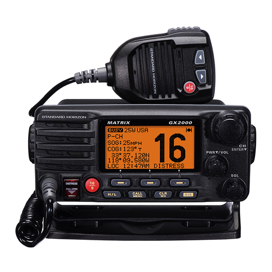
MATRIX SERIES
GX2000 and GX2150
25 Watt VHF/FM
Marine Transceivers
Owner's Manual
Integrated dual channel AIS (Automatic Identification System) receiver (GX2150)
AIS (Automatic Identification System) receiver or transponder connection (GX2000)
4800 or 38400 NMEA baud rate selection for plotters with 1 NMEA port (GX2150)
Able to use PA or Fog signaling when on AIS display (GX2150)
True and Magnetic bearing selection on AIS display
AIS target display: MMSI, Call Sign, Ship Name, BRG, DST, SOG and COG
Contact Class A or B AIS Ship with DSC
Programmable CPA or TCPA collision avoidance alarms
ITU Class D DSC (Independent Channel 70 receiver built-in)
80dB Commercial grade receiver
DSC position request and report functions
Navigate to a DSC Distress Call
30 Watt PA/Loud Hailer with pre-programmed fog signals and (listen back GX2150)
ClearVoice noise canceling speaker microphone with channel selection and 16/9 key
GPS Compass, Waypoint and GPS status pages
Navigation (LAT/LON, Time, SOG and COG) information shown on display
Enter, Save and Navigate to waypoints with Compass page
User programmable soft keys
Versatile user-programmable scanning, priority scan and Dual Watch
Oversized rotary channel knob with push to enter, backlit display and keys
Optional connection for RAM3 second station remote microphone with AIS display
Intercom between radio and RAM3
Voice Scrambler (optional)
Local/Distance attenuator
Submersible JIS-7 / IPX7 (3.3 feet for 30 minutes)
E2O (Easy-To-Operate) menu system
When connected to a GPS
MATRIX AIS+ GX2150
MATRIX GX2000
Advertisement
Table of Contents

Subscribe to Our Youtube Channel
Related Manuals for Standard Horizon MATRIX Series


Summary of Contents for Standard Horizon MATRIX Series
- Page 1 MATRIX SERIES GX2000 and GX2150 25 Watt VHF/FM Marine Transceivers Owner's Manual Integrated dual channel AIS (Automatic Identification System) receiver (GX2150) AIS (Automatic Identification System) receiver or transponder connection (GX2000) 4800 or 38400 NMEA baud rate selection for plotters with 1 NMEA port (GX2150)
-
Page 2: Table Of Contents
TABLE OF CONTENTS Quick Reference Guide .................... 4 9 DIGITAL SELECTIVE CALLING ..............42 1 GENERAL INFORMATION ................5 GENERAL ..................42 2 PACKING LIST ....................6 MARITIME MOBILE SERVICE IDENTITY (MMSI) ......42 3 OPTIONS ......................6 9.2.1 What is an MMSI? .............. 42 4 ON-LINE WARRANTY REGISTRATION ( in USA or Canada only ) .... - Page 3 TABLE OF CONTENTS 10 GENERAL SETUP ................... 77 14 WAYPOINTS ....................102 10.1 DISPLAY .................... 77 14.1 MARKING A POSITION ..............102 10.2 LOCAL DISTANCE RECEIVER ATTENUATOR ......78 14.2 ADDING A WAYPOINT ..............103 10.3 DIMMER ADJUSTING ............... 79 14.3 EDITING A WAYPOINT ..............
- Page 4 This transceiver is equipped with the E2O (Easy-To-Operate) system. Basic operation may be accomplished by following the procedure below: Press and hold the PWR /VOL knob to turn on or off the radio. Rotate the PWR /VOL knob to adjust the speaker audio volume. Rotate the CHANNEL knob (or press the microphones button) to select the operating channel.
-
Page 5: General Information
MATRIX AIS, the MATRIX GX2000 has a connection for an AIS receiver or transponder. The MATRIX Series VHF’s are capable of DSC (Digital Selective Calling) ITU Class D operation. Class D operation allows continuous receiving of Digital Selective Calling functions on channel 70 even if the radio is receiving a call. -
Page 6: Packing List
2 PACKING LIST When the package containing the transceiver is first opened, please check it for the following contents: GX2000 or GX2150 Transceiver Mounting Bracket and hardware Owner’s Manual DSC Warning Sticker Flush Mount Template Power Cord Dust Cover 3 OPTIONS MMB-84 ................. -
Page 7: Getting Started
5 GETTING STARTED PROHIBITED COMMUNICATIONS The FCC prohibits the following communications: • False distress or emergency messages: • Messages to “any boat” except in emergencies and radio tests; • Messages to or from a vessel on land; • Transmission while on land; •... -
Page 8: Coaxial Cable
COAXIAL CABLE VHF antennas are connected to the transceiver by means of a coaxial cable – a shielded transmission line. Coaxial cable is specified by it’s diameter and construction. For runs less than 20 feet, RG-58/U, about 1/4 inch in diameter is a good choice. -
Page 9: Calling Another Vessel (Channel 16 Or 9)
7. Estimate the present seaworthiness and condition of your vessel. 8. Give your vessel’s description: length, design (power or sail), color and other distinguishing marks. The total transmission should not exceed 1 minute. 9. End the message by saying “OVER”. Release the microphone button and listen. -
Page 10: Making Telephone Calls
After a transmission, say “over,” and release the microphone’s push-to-talk (PTT) switch. When all communication with the other vessel is completed, end the last transmission by stating your Call Sign and the word “out.” Note that it is not necessary to state your Call Sign with each transmission, only at the beginning and end of the contact. -
Page 11: What Is The Range For Ais Receivers
The Automated Radio Check Service is currently available in the areas listed below. West Coast Sea Tow Newport/LA - Ch. 27 Sea Tow San Diego - Ch. 27 Northeast Sea Tow Portland-Midcoast (Maine) - Ch. 27 Sea Tow Boston - Ch. 27 Sea Tow South Shore (Mass.) - Ch. -
Page 12: Installation
6 INSTALLATION SAFETY / WARNING INFORMATION This radio is restricted to occupational use, work related operations only where the radio operator must have the knowledge to control the exposure condi- tions of its passengers and bystanders by maintaining the minimum separa- tion distance of 0.89 m (2.92 feet). -
Page 13: Mounting The Radio
MOUNTING THE RADIO 6.3.1 Supplied Mounting Bracket The supplied mounting bracket allows overhead or desktop mounting. Use a 13/64” (5.2-mm) bit to drill the holes to a surface which is more 0.4 inch (10 mm) thick and can support more than 3.3 lbs (1.5 kg) and secure the bracket with the supplied screws, spring washers, flat washers, and nuts. -
Page 14: Electrical Connections
ELECTRICAL CONNECTIONS CAUTION Reverse polarity battery connections will damage the radio! Connect the power cord and antenna to the radio. Antenna and Power Supply connections are as follows: 1. Mount the antenna at least 3 feet (1 m) away from the radio. At the rear of the radio, connect the antenna cable. -
Page 15: Accessory Cables
ACCESSORY CABLES 6.5.1 MATRIX GX2000 Connection The image and table below show the wires of the MATRIX (GX2000) and the connections to optional devices such as a PA Speaker (Horn), External Speaker, GPS Chart plotter and a AIS receiver or Transponder. The MATRIX uses NMEA 0183 protocol to communicate to a GPS chart plotter and a AIS device. -
Page 16: Matrix Ais+ Connections
MATRIX AIS+ CONNECTIONS The image and table below show the wires of the MATRIX AIS+ (GX2150) and the connections to optional devices such as a PA Speaker (Horn), External Speaker and a GPS Chart plotter. The GX2150 uses NMEA 0183 protocol to share coordinates, DSC and AIS information to and from a GPS chart plotter. -
Page 17: Matrix Ais+ 38400 Baud Connections
6.6.2 MATRIX AIS+ 38400 Baud Connections Use the image and table below when connecting to a GPS Chart plotter which has one NMEA 0813 ComPort. PA Speaker Shield GPS Receiver Radio Wires Plotter Connection Gray: NMEA Output ( ) NMEA-HS IN ( ) Blue: NMEA Input ( ) NMEA HS OUT ( ) NMEA COMMON ( ) - Page 18 GPS Connections ( GX2000: 4800 baud ) NMEA INPUT (GPS Information) • The GPS must have the NMEA Output turned on and set to 4800 Baud in the setup menu. If there is a selection for parity select none. • For further information on interfacing /setting up your GPS.
-
Page 19: Checking Gps Connections
CHECKING GPS CONNECTIONS After connections have been made between the GX2000/GX2150 and the GPS, a small satellite icon will appear on the top right corner of the display and your current location (Latitude/Longitude) will be shown on the display. NOTE If there is a problem with the NMEA connection between the radio and the GPS, the GPS icon will blink continuously until the connection is corrected. -
Page 20: Changing The Time Area
CHANGING THE TIME AREA This menu selection allows the radio to show UTC time or your local time with the offset which is enabled in section “6.8 CHANGING THE GPS TIME”. 1. Press and hold down the key until “Setup Menu”... -
Page 21: Changing Cog To True Or Magnetic
6.11 CHANGING COG TO TRUE OR MAGNETIC Allows the GPS COG (Course Over Ground) and the BRG from a AIS target to be selected to show in True or Magnetic. Factory default is True however by following the steps below the COG can be changed to Magnetic. 1. - Page 22 5. Referring to illustration below, make a 1.2” (30 mm) hole in the wall, then insert the Extension Cable into this hole. Connect the Gasket and Mount Base to the Extension Cable Connector using the Nut. 6. Drill the four Screw holes (approx. 2 mm) on the wall, then install the Mount- ing Base to the wall using four screws.
-
Page 23: Connecting An External Speaker
6.12.1 Connecting an External Speaker to the RAM3 Mic Cable In noisy locations and optional external speaker may be connected to the white speaker wires on the RAM3 ( CMP30 ) routing cable. The RAM3 ( CMP30 ) can drive the internal speaker or the external speaker one at a time. When con- necting an external speaker, follow the procedure below to turn off the RAM3 ( CMP30 ) audio and enable the external speaker wires on the RAM3 ( CMP30 ) routing cable. -
Page 24: Controls And Indicators
7 CONTROLS AND INDICATORS NOTE This section defines each control of the transceiver. See illustration at the next page for location of controls. For detailed operating instructions refer to chapter 8 of this manual. FRONT PANEL CHANNEL Knob Rotary knob is used to select channels and to choose menu items (such as the DSC menu, Radio Setup and DSC Setup menu). - Page 25 SQL Knob ( Squelch Control ) Adjusting this control clockwise, sets the point at which random noise on the channel does not activate the audio circuits but a received signal does. This point is called the squelch threshold. Further adjustment of the squelch control will degrade reception of wanted transmissions.
-
Page 26: Rear Panel
Press the key briefly to recall channel 16 from any channel location. Press and hold the key to recall channel 9. Pressing the [16/9] key again reverts to the previous selected working channel. [ DISTRESS ] Key Used to send a DSC Distress Call. To send the distress call refer to section “9.3.1 Transmitting a DSC Distress Alert”. - Page 27 PA Speaker Connection Cable ( Red & Shield ) Connects the GX2000/GX2150 to a optional PA speaker. Refer to section “3 OPTIONS” for a list of optional STANDARD HORIZON Speakers. External Speaker Connection Cable ( White & Shield ) an external speaker. See section “3 OPTIONS” for a list of optional STAN- DARD HORIZON Speakers.
-
Page 28: Microphone
MICROPHONE PTT Switch ( Push-To-Talk Switch ) 1. When in radio mode and the PTT button pressed, the transmitter is enabled for voice communications to another vessel. 2. When PA mode is selected, pressing the PTT button allows your voice to be amplified and supplied to a connected PA horn. -
Page 29: Basic Operation
8 BASIC OPERATION RECEPTION 1. After the transceiver has been installed, ensure that the power supply and antenna are properly connected. 2. Press and hold the PWR /VOL knob until the radio turns on. 3. Rotate the SQL knob fully counterclockwise. This state is known as “squelch off”. -
Page 30: Simplex/Duplex Channel Use
SIMPLEX/DUPLEX CHANNEL USE Refer to the VHF MARINE CHANNEL CHART (page 117) for instructions on use of simplex and duplex channels. NOTE All channels are factory-programmed in accordance with FCC (USA), Industry Canada (Canada), and International regulations. Mode of op- eration cannot be altered from simplex to duplex or vice-versa. -
Page 31: Usa, Canada, And International Mode
6. Press the soft key several times to return to radio operation. NOTE To show Position information, show AIS targets and use the Compass display: GX2150 - external GPS must be connected. GX2000 - external AIS receiver or transponder and a external GPS must be connected. -
Page 32: Noaa Weather Alert Testing
When an alert is received on a NOAA weather channel, scanning will stop and the transceiver will emit a loud beep to alert the user of a NOAA broadcast. Pess any key to stop the alert and receive the weather report. Press the soft key to return to the last selected channel. -
Page 33: Preset Channels 0 ~ 9 : Instant Access
PRESET CHANNELS 0 ~ 9 : INSTANT ACCESS 10 Preset Channels can be programmed for instant access. Press the one of soft keys, then press the soft key to activate the preset channel bank. If the soft is pressed and no channels have been assigned, an alert beep will be emitted from the speaker. -
Page 34: Scanning
5. Repeat steps 2 through 4 to delete the desired channels from Preset Chan- nels “0” ~ “9”. 6. To finish the deleting the Preset Channel, press the soft key 8.10 SCANNING The GX2000/GX2150 will automatically scan channels programmed into Pre- set Channel Memory and also Scan Channel Memory, and last selected Weather Channel. -
Page 35: Scan Memory Programming
8.10.2 Scan Memory Programming 1. Press and hold down the key until “Setup Menu” appears. 2. Rotate the CHANNEL knob to select “CH FUNCTION SETUP”. 3. Press the soft key, then rotate the CHAN- NEL knob to select “SCAN MEMORY”. 4. -
Page 36: Pa/Fog Operation
The GX2000/GX2150 has a 30W Hailer built-in and can be used with any 4 Ohm PA Horns. Standard Horizon offers a small and a large PA horn called the 220SW and 240SW. When in Hail mode the PA speaker Listen’s Back (acts as... -
Page 37: Fog Horn Operation
NOTE When in the PA HAIL mode it is possible to simultaneously use the AIS page by press the key. 8.11.2 FOG HORN Operation The user can select from “Underway”, “Stop”, “Sail”, “Tow”, “Aground”, “An- chor”, “Horn”, and “Siren”. 1. Press the one of the soft keys momentarily, then press the soft key. -
Page 38: Fog Signal Timing Chart
8.11.3 Fog Signal Timing Chart TYPE PATTERN UNDERWAY One 5-second blasts every 120 seconds. Motor vessel underway and making way. Listen Back 120s STOP Two 5-second blasts (separated by 2 Motor vessel underway but seconds) every 120 seconds. stopped (not making way). Listen Back 120s SAIL... -
Page 39: Intercom Operation
8.12 INTERCOM OPERATION To access the following Intercom functions one of the soft keys must be setup as IC. Refer to section “10.14 SOFT KEYS”. In addition an optional RAM3 ( CMP30 ) Remote Station Microphone must be connected to perform intercom functions between the GX2000/GX2150 and the RAM3 ( CMP30 ) . -
Page 40: Voice Scrambler
8.13 VOICE SCRAMBLER If privacy of communications is desired, a CVS2500 4 code voice scrambler (VS) can be installed in the transceiver. Contact your Dealer to have a CVS2500 installed. Refer to the section “11.8 SCRAMBLER SETUP” to program the voice scrambler. -
Page 41: Digital Selective Calling
9 DIGITAL SELECTIVE CALLING GENERAL WARNING This radio is designed to generate a digital maritime distress and safety call to facilitate search and rescue. To be effective as a safety device, this equipment must be used only within communication range of a shore- based VHF marine channel 70 distress and safety watch system. -
Page 42: Programming The Mmsi
9.2.2 Programming the MMSI WARNING A user MMSI can be inputted only once. Therefore please be careful not to input the incorrect MMSI number. If you need to change the MMSI number after it has been entered, the radio will have to be returned to Factory Service. -
Page 43: Dsc Distress Alert
DSC DISTRESS ALERT The GX2000/GX2150 is capable of transmitting and receiving DSC Distress messages to all DSC radios. The GX2000/GX2150 may be connected to a GPS to also transmit the Latitude, Longitude of the vessel. 9.3.1 Transmitting a DSC Distress Alert NOTE To be able to transmit a DSC Distress Alert an MMSI number must be programmed, refer to section “9.2.2 Programming the MMSI.”... -
Page 44: Transmitting A Dsc Distress Alert With Nature Of Distress
9.3.1.1 Transmitting a DSC Distress Alert with Nature of Distress The GX2000/GX2150 is capable of transmitting a DSC Distress Alert with the following “Nature of Distress” categories: Undesignated, Fire, Flooding, Collision, Grounding, Capsizing, Sinking, Adrift, Abandoning, Piracy, MOB 1. Lift the red spring loaded DISTRESS cover and press the [ DISTRESS ] key. - Page 45 2. Press the soft key. 3. Enter the latitude/longitude of your vessel and your local UTC time in the 24-hour notation by the CHAN- NEL knob. Rotate the CHANNEL knob to select the number and press the soft key to move the cursor to the next character.
-
Page 46: Pausing A Dsc Distress Call
9.3.1.3 Pausing a DSC Distress Call After a DSC Distress call is transmitted, the DSC distress call is repeated every 4 minutes until the call is canceled by the user or until the radio is turned on and off again. The GX2000/GX2150 has provision to suspend (Pause) the retransmitting of the distress call by the procedure below. -
Page 47: Quit
(select the letter/number by rotating the CHANNEL knob and move the cursor by pressing the soft key). Received DISTRESS Name:VERTEX ID:123456789 6. The ID is the MMSI from the vessel in distress. Since: 01:03 -DISTRESS INFO- 7. When you are finished entering the waypoint name, Nature of:Undesignate DIST ID:123456789 press and hold the... -
Page 48: All Ships Call
ALL SHIPS CALL The All Ships Call function allows contact to be established with DSC equipped vessels without having their MMSI in the individual calling directory. Also, pri- ority for the call can be designated as Urgency or Safety. URGENCY Call: This type of call is used when a vessel may not truly be in distress, but have a potential problem that may lead to a dis- tress situation. -
Page 49: Receiving An All Ships Call
9.4.2 Receiving an All Ships Call 1. When an all ships call is received, an emergency alarm will sound. The display shows the MMSI of the vessel trans- mitting the All Ships Call and the radio will change to the requested channel after 10 seconds. 2. -
Page 50: Individual Call
INDIVIDUAL CALL This feature allows the GX2000/GX2150 to contact another vessel with a DSC VHF radio and automatically switch the receiving radio to a desired communi- cations channel. This feature is similar to calling a vessel on CH16 and re- questing to go to another channel (switching to the channel is private between the two stations). -
Page 51: Individual Reply Setup
desired number and move one space to the right by pressing the soft key. Repeat this procedure until all nine space of the MMSI number are entered. 11. If a mistake was made entering in the MMSI number repeat pressing the soft key until the wrong number is selected, then rotate the CHANNEL knob to correct the entry. -
Page 52: Individual/Group Call Ringer Setup
TO COMPLY” or “UNABLE”. 6. Press the soft key to store the selected set- ting, then press the soft key several times to return to radio operation. 9.5.4 Individual/Group Call Ringer Setup When a Individual Call or Group Call is received the radio will produce a ring- ing sound for 2 minutes. -
Page 53: Transmitting An Individual Call
9.5.5 Transmitting an Individual Call This feature allows the user to contact another vessel with a DSC radio. This feature is similar to calling a vessel on CH16 and requesting to go to another channel. 9.5.5.1 Individual Call using the Individual Directory 1. -
Page 54: Individual Call By Manually Entering A Mmsi
9.5.5.2 Individual Call by Manually Entering a MMSI You may enter an MMSI number manually to contact without storing it in the Individual Directory. 1. Press the key. The “DSC Menu” menu will ap- pear. 2. Rotate the CHANNEL knob to select “INDIVIDUAL”. (To cancel, press the soft key.) 3. -
Page 55: Receiving An Individual Call
and a ringing tone sounds. 12. Press the soft key to listen to the channel to make sure it is not busy, then press the microphone’s PTT switch and talk into the micro- phone to the other vessel. 9.5.6 Receiving an Individual Call When a Individual DSC call is received, the radio will automatically respond (Default setting) to the calling ship, and switch to the requested channel for voice communications. -
Page 56: Dsc Log Operation
DSC LOG OPERATION The GX2000/GX2150 logs received distress calls and individual calls. The DSC Log feature is similar to an answer machine where calls are recorded for review and a “ ” icon will appear on the radios display. The GX2000/GX2150 can store up to the latest 26 Distress, and up to the latest 64 other calls (Indi- vidual, Group, All Ship etc.). -
Page 57: Reviewing A Logged All Ship Or Individual Call
9.6.2 Reviewing a Logged All Ship or Individual Call Reviewing a logged All ship or Individual call. 1. Press the key. The “DSC Menu” will ap- pear. 2. Rotate the CHANNEL knob to select “DSC LOG” menu. 3. Press the soft key, then rotate the CHAN- NEL knob to select “OTHER CALL LOG”. -
Page 58: Deleting A Call From The "Dsc Log" Directory
9.6.3 Deleting a Call from the “DSC LOG” Directory 1. Press the key. The “DSC Menu” will ap- pear. 2. Rotate the CHANNEL knob to select “DSC LOG” menu. 3. Press the soft key, then rotate the CHAN- NEL knob to select “LOG DELETE” menu. 4. -
Page 59: Group Call
MMSI numbers. The first digit of a Group MMSI is always set to “0” by International rules. All Standard Horizon radios are preset so when programming a Group MMSI the first digit is set to “0”. -
Page 60: Transmitting A Group Call
5. Press the soft key. 6. Rotate the CHANNEL knob to scroll through the first letter of the name of the group you want to refer- ence in the directory. 7. Press the soft key to store the first letter in the name and step to the next letter to the right. -
Page 61: Group Call By Manually Entering A Mmsi
NEL knob to select the operating channel you want to communicate on, then press the soft key. If the channel you want is not shown, press the soft key, then rotate the CHANNEL knob to select the operating channel you want to communicate on, then press soft key. -
Page 62: Receiving A Group Call
number, repeat pressing the soft key until the wrong number is selected, then rotate the CHAN- NEL knob to correct the entry. 9. When finished entering the MMSI number, press and hold the soft key. 10. Rotate the CHANNEL knob to select the operating channel you want to communicate on, then press the soft key. -
Page 63: Position Request
Advancements in DSC have made it possible to poll the location of another vessel and show the position of that vessel on the display of the GX2000/ GX2150. Standard Horizon has taken this feature one step further, if any com- patible GPS chart plotter is connected to the GX2000/GX2150, the polled po- sition of the vessel is shown on the display of the GPS chart plotter making it easy to navigate to the location of the polled vessel. -
Page 64: Position Request Ringer Setup
9.8.2 Position Request Ringer Setup The GX2000/GX2150 has the capability to turn off the Position Request ringer. 1. Press and hold down the key until “Setup Menu” appears. 2. Rotate the CHANNEL knob to select “DSC SETUP” menu. 3. Press the soft key, then select “DSC BEEP”... -
Page 65: Position Request By Manually Entering A Mmsi
9.8.3.2 Position Request by Manually Entering a MMSI This feature allows you to request the position of vessel by manually entering the MMSI of the ship you want to send your position to. 1. Press the key. The “DSC Menu” will appear. - Page 66 Manually reply: 1. When a position request call is received from an- other vessel, the display will be as shown in the il- lustration at the right. 2. A ringing alarm sounds 4 times. To send your ves- sels position to the requesting vessel, press the soft key.
-
Page 67: Position Report
POSITION REPORT The feature is similar to Position Request, however instead of requesting a position of another vessel this function allows you to send your position to another vessel. Your vessel must have an operating GPS receiver connected for the GX2000/GX2150 to send the position. NOTE To transmit a Position Report Call, a GPS must be connected to the radio and the GX2000 / GX2150 Individual directory must be programmed... -
Page 68: Dsc Position Report Call By Manually Entering A Mmsi
5. Press the soft key to send your posi- tion to the selected vessel. 6. Press the soft key to return to radio operation. 9.9.2.2 DSC Position Report Call manually entering a MMSI This feature allows you to send your position to another vessel by manually entering the MMSI of the ship you want to send your position to. -
Page 69: Receiving A Dsc Position Report Call
9.9.3 Receiving a DSC Position Report Call When another vessel transmits their vessels location to the GX2000/GX2150 the following will happen: 1. A ringing sound will be produced when the call is received and NMEA sentences DSC, DSE are outputted so the position can be shown on a chart plotter or a computer. -
Page 70: Saving A Position Report Call As A Waypoint
9.9.6 Saving a Position Report as a Waypoint The GX2000/GX2150 can save a Position Report call in the radios memory as a waypoint. 1. After the Position Report call has been re- ceived: Press the soft key. 2. Rotate the CHANNEL knob to change the first letter in the name of the waypoint and press soft key. - Page 71 9.10 MANUAL INPUTTING OF THE GPS LOCATION LAT/LON You may send the Latitude/Longitude of your vessel manually even if the GX2000/GX2150 is not connected the GPS receiver unit. After the position is entered, transmitting a DSC Distress, Position Request, or Position Report will contain the manually entered position.
-
Page 72: Auto Dsc Polling
9.11 AUTO DSC POLLING The GX2000/GX2150 has the capability to automatically track four stations programmed into the Indvidual directory. The following procedure allows the time interval between position requests to be setup. 9.11.1 Polling Time Interval Setup 1. Press and hold down the key until “Setup Menu”... -
Page 73: Enable/Disable Auto Dsc Polling
and CALL 4 entries. 7. When finished, press the soft key numer- ous times to exit to the radio mode. 9.11.3 Enable/Disable Auto DSC Polling 1. Press the key. The “DSC Menu” will ap- pear. 2. Rotate the CHANNEL knob to select “AUTO POS POLLING”, then press the soft key. -
Page 74: Dsc Test
9.12 DSC TEST This function is used to contact another DSC equipped vessel to ensure the DSC functions of the radio are operating. NOTE To use this feature, the radio you will be transmitting the test call to needs to have the DSC Test feature. To perform the DSC test you will need to enter a MMSI of another vessel into the Individual directory or manually enter in the MMSI using the procedure below. -
Page 75: Dsc Test Call By Manually Entering A Mmsi
9.12.3 DSC Test Call by Manually Entering a MMSI 1. Press the key. The “DSC Menu” will ap- pear. 2. Rotate the CHANNEL knob to select “DSC TEST”, then press the soft key. 3. Rotate the CHANNEL knob to select “MANUAL” and press the soft key. -
Page 76: General Setup
10 GENERAL SETUP The optional RAM3 ( CMP30 ) Remote Station Microphone can also change the SETUP menu using the following procedure. 10.1 DISPLAY The GX2000/GX2150 can select additional screens other than the default normal (Radio) display by using the procedure below. “NORMAL”... -
Page 77: Local Distance Receiver Attenuator
NOTE To show Position information, show AIS targets and use the Compass display: GX2150 - external GPS must be connected. GX2000 - external AIS receiver or transponder and a external GPS must be connected. 10.2 LOCAL DISTANCE RECEIVER ATTENUATOR In some areas, signals from external sources may cause interference to re- ceiving marine transmissions. -
Page 78: Dimmer Adjusting
10.3 DIMMER ADJUSTING This menu selection adjusts the backlight intensity. 1. Press and hold down the key until “Setup Menu” appears. 2. Rotate the CHANNEL knob to select “GENERAL SETUP” menu. 3. Press the soft key, then select “DIMMER” with the CHANNEL knob. 4. -
Page 79: Time Offset
10.5 TIME OFFSET Sets the time offset between local time (with inputted offset) and UTC (without time offset) shown on the display. Time is displayed only when an optional GPS Chart Plotter is connected. 1. Press and hold down the key until “Setup Menu”... -
Page 80: Time Area
10.6 TIME AREA This menu selection allows the radio to show UTC time or local time with the offset. 1. Press and hold down the key until “Setup Menu” appears, then select “GENERAL SETUP” with the CH knob. 2. Press the soft key, then rotate the CHAN- NEL knob to “TIME AREA”. -
Page 81: Unit Of Measure
10.8 UNIT OF MEASURE Allows Navigation and AIS displays to be shown in “Knot”, “Mile/Hour” or “Kilo- Meter/Hour” (for speed) and “Nautical Mile” or “Kilo-Meter” (for distance). NOTE A GPS must be connected to the radio to be able to show SPEED and DISTANCE. -
Page 82: Nmea Data In/Out
10.10 NMEA DATA IN/OUT This section is used to setup the NMEA 0183 baud rate of the GPS input (Blue wire) and DSC output (Gray wire). The default setting is 4800 BPS. When 38400 BPS is selected the AIS sentences (VDM) and DSC sentences (DSC & DSE) both are output on the Gray wire after a DSC Distress, Position Request or AIS transmission is received. -
Page 83: Fog Alert Tone Frequency
10.12 FOG ALERT TONE FREQUENCY The function allows the radio to be setup to send the proper fog frequency which is dependant on vessel size, shown below: 70 - 200Hz: Vessel that are 200 meters or more in length 130 - 350Hz: Vessel that are 75 Meters but less than 200 meters or more in length 250 - 525Hz: Vessel that are 66 Feet (20 Meters) but less than 247.5 Feet (75 Meters) in length... -
Page 84: Station Name
10.13 STATION NAME This function allows you to change the name of the radio or second station microphone. Example: “Radio - Cabin”, “RAM1 - Flybridge”. 1. Press and hold down the key until “Setup Menu” appears, then select “GENERAL SETUP” with the CHANNEL knob. -
Page 85: Soft Keys
10.14 SOFT KEYS This menu item allows selection of the number of soft keys, soft key selection and how long the display will show the soft key icon after a soft key is pressed. 10.14.1 Selecting the Number of Soft Keys 1. -
Page 86: 1014.3 Selecting How Long The Soft Keys Are Shown
10.14.3 Selectiong How Long the Soft Keys are Shown 1. Press and hold down the key until “Setup Menu” appears, then select “GENERAL SETUP” with the CHANNEL knob. 2. Press the soft key, then rotate the CHANNEL knob to “SOFT KEY”. 3. -
Page 87: Channel Function Setup
11 CHANNEL FUNCTION SETUP 11.1 CHANNEL GROUP This section selects a channel group from USA, Canada, and International. 1. Press and hold down the key until “Setup Menu” appears. 2. Rotate the CHANNEL knob to select “CH FUNCTION SETUP”. 3. Press the soft key, then rotate the CHANNEL knob to select “CH GROUP”. -
Page 88: Scan Type
11.3 SCAN TYPE This selection is used to select the scan mode between “Memory Scan” and “Priority Scan”. The default setting is Priority Scan. 1. Press and hold down the key until “Setup Menu” appears. 2. Rotate the CHANNEL knob to select “CH FUNCTION SETUP”. -
Page 89: Priority Channel
11.5 PRIORITY CHANNEL By default the radio priority channel is set to channel 16. This procedure allows the radio to use a different priority channel used when priority scanning. 1. Press and hold down the key until “Setup Menu” appears. 2. -
Page 90: Channel Name
11.7 CHANNEL NAME When radio mode (NORMAL) is selected, the display will show a name under the channel number. This name describes the use of the channel. The radio has the capability to customize the name by the procedure below. Example: CH69 PLEASURE to HOOKUP 1. -
Page 91: Scrambler Setup
11.8 SCRAMBLER SETUP NOTE Operates only when the optional CVS2500 is installed. This menu will not appear unless a CVS2500 is installed. 1. Press and hold down the key until “Setup Menu” appears. 2. Rotate the CHANNEL knob to select “CH FUNCTION SETUP”. -
Page 92: Demo Mode
11.9 DEMO MODE This mode is used by Standard Horizon sales persons and dealers to demon- strate radio, DSC and AIS functions in show rooms or at boat shows. Demo mode allows Latitude, longitude and time to be entered to simulate radio dis- plays. -
Page 93: Dsc Setup
12 DSC SETUP 12.1 INDIVIDUAL DIRECTORY The GX2000/GX2150 has a DSC directory that allows you to store a vessel or person’s name and the MMSI number associated with vessels you wish to transmit Individual calls, Position Requests and Position Send transmissions. To transmit an Individual call you must program this directory with information of the persons you wish to call, similar to a cellular phones telephone directory. -
Page 94: Position Reply
14.6 POSITION REPLY The GX2000/GX2150 can be set up to automatically (default setting) or manu- ally send your position when requested by another vessel. This selection is important if you are concerned about someone polling the position of your vessel that you may not want to. In the manual mode you will see the MMSI or persons name shown on the display allowing you to choose to send your posi- tion to the requesting vessel. -
Page 95: Ais/Compass Setup
13 AIS/COMPASS SETUP 13.1 AUTOMATIC IDENTIFICATION SYSTEM AIS NOTE The MATRIX AIS+ GX2150 does not require a special marine VHF an- tenna to receive AIS transmissions. The MATRIX AIS+ GX2150 does not transmit AIS signals, it is NOT recommended to use an antenna dedicated for AIS operation. -
Page 96: Direction
13.2 DIRECTION This function allows you to select the top of the AIS compass to be orientated in Course Up or North Up. 1. Press and hold down the key until “Setup Menu” appears. 2. Rotate the CHANNEL knob to select “AIS/ COMPASS SETUP”. -
Page 97: Cpa Alert
13.4 CPA ALARM This function allows you to set the CPA (Closest Point of Approach) alarm distance. : CPA means the positions at which two moving vessels reach their closest possible distance. 1. Press and hold down the key until “Setup Menu”... -
Page 98: Display Range
4. Press the soft key. 5. Rotate the CHANNEL knob to select the time that the TCPA alarm will sound. 6. Press the soft key, then rotate the CHANNEL knob to set the Alarm item to “On”. 7. Press the soft key to store the selected set- ting. -
Page 99: Ais Operation
13.7 AIS OPERATION The GX2150 is equipped with an AIS ( A ) receiver UTOMATIC DENTIFICATION YSTEM and can display AIS targets around your vessel on the radios display. There- fore, you can identify and avoid other large vessels nearby your vessel. The GX2000 can also show AIS targets, however a separate AIS receiver or transponder with NMEA VDM 34800 baud must be connected to the acces- sory cable. -
Page 100: Transmitting And Individual Call To An Ais Ship
13.7.1 Transmitting and Individual Call to an AIS Ship It is possible for the GX2000 or GX2150 to transmit a DSC Individual call to a received AIS target by the procedure below: 1. Press the one of the soft keys momentarily, then press the soft key. -
Page 101: Waypoints
14 WAYPOINTS The GX2000/GX2150 is capable of storing up to 100 waypoint and navigating to them using the compass page. In addition DSC distress calls with position or a position received from a an- other DSC radio using DSC polling can be navigated to. 14.1 MARKING A POSITION This feature allows the radio to mark the current position of the vessel. -
Page 102: Adding A Waypoint
14.2 ADDING A WAYPOINT 1. Press and hold down the key until “Setup Menu” appears. 2. Rotate the CHANNEL knob to select “WAYPOINT SETUP”. 3. Press the soft key, then select “WAYPOINT DIRECTORY” with the CHANNEL knob. 4. Press the soft key, then select “ADD”... -
Page 103: Editing A Waypoint
14.3 EDITING A WAYPOINT This function allows a previously entered waypoint to be edited. 1. Press and hold down the key until “Setup Menu” appears. 2. Rotate the CHANNEL knob to select “WAYPOINT SETUP”. 3. Press the soft key, then select “WAYPOINT DIRECTORY”... -
Page 104: Saving A Dsc Position Call As A Waypoint
14.5 SAVING A DSC POSITION CALL AS A WAYPOINT When a position is received from a another DSC radio the GX2000/GX2150 allows the position to be saved as a waypoint. 1. After a position has been received, press the soft key two times. 2. -
Page 105: Stop Navigating To A Waypoint
14.7 STOP NAVIGATING TO A WAYPOINT 1. Press the one of the Soft key to show the key selec- tions. 2. Press the key. The radio will stop navigat- ing to a the waypoint and the Normal VHF display will be shown. Page 106 GX2000/GX2150... -
Page 106: Ram3 Cmp30 Remote Mic Operation
15 RAM3 CMP30 REMOTE MIC OPERATION When the Remote MIC is connected to the GX2000/GX2150, all VHF, DSC, setup menus, AIS, Waypoint, Compass functions and PA/Fog modes can be remotely operated. The RAM3 ( CMP30 ) Remote Station Microphone opera- tion is same as GX2000/GX2150 except the receiver audio volume setting and squelch level setting. - Page 107 PTT (Push-To-Talk) Key Push this key to enable the transmitter. ( POWER ) Key Press and hold down this key to turn the transceiver and Remote MIC on or off. MICROPHONE The internal ClearVoice Noise Canceling mic is located here. When transmitting, position your mouth about 1/2 to 1 inch (1.2 ~ 2.5 cm) away from the small mic hole.
-
Page 108: Assigning Soft Keys
Press to CLEAR a function or menu selection. Press and hold to select NOAA Weather channels. Press and hold again to exit Weather mode and revert to radio mode. Secondary use Hold down the key while pressing the key to change the mode from USA to International or Canadian. - Page 109 gram the other soft keys. 7. Press the soft key, then press the key to select “KEY TIMER” (selects how long the soft key icon will be shown on the display after a soft key is pressed, default is 5 seconds).
-
Page 110: Maintenance
Ensure that the supply voltage to the transceiver does not exceed 16 VDC or fall below 11 VDC. • Use only STANDARD HORIZON-approved accessories and replacement parts. In the unlikely event of serious problems, please contact your Dealer or our repair facility. -
Page 111: Troubleshooting Chart
16.2 TROUBLESHOOTING CHART SYMPTOM PROBABLE CAUSE REMEDY Transceiver fails to No DC voltage to the a. Check the 12VDC battery connections and power up. transceiver, or blown the fuse. fuse. b. The VOL/PWR knob needs to be pressed and held to turn the radio on. Transceiver blows fuse R e v e r s e d p o w e r Check the power cable for DC voltage, or re-... -
Page 112: Channel Assignments
17 CHANNEL ASSIGNMENTS Tables on the following columns list the VHF Marine Channel assignments for U.S.A. and International use. Below are listed some data about the charts. 1. VTS. Where indicated, these channels are part of the U.S. Coast Guard’s Vessel Traffic System. - Page 113 6. Marine vessels equipped with VHF radios are required to monitor Channel 7. 156.050 MHz and 156.175 MHz are available for port operations and com- mercial communications purposes when used only within the U.S. Coast Guard designated Vessel Traffic Services (VTS) area of New Orleans, on the lower Mississippi River from the various pass entrances in the Gulf of Mexico to Devil’s Swamp Light at River Mile 242.4 above head of passes near Baton Rouge.
- Page 114 12. Use of 156.375 MHz is available for navigational communications only in the Mississippi River from South Pass Lighted Whistle Buoy “2” and South- west Pass entrance Mid channel Lighted Whistle Buoy to mile 242.4 above head of Passes near Baton Rouge, and in addition over the full length of the Mississippi River-Gulf Outlet Canal from entrance to its junction with the Inner Harbor Navigation Canal, and over the full length of the Inner Harbor Navigation Canal from its junction with the Mississippi River to its...
- Page 115 VHF MARINE CHANNEL CHART CHANNEL USE D 156.050 160.650 Public Correspondence (Marine Operator) 156.050 Port Operation and Commercial. VTS in selected areas D 156.100 160.700 Public Correspondence (Marine Operator) D 156.150 160.750 Public Correspondence (Marine Operator) 156.150 U.S. Government Only, Coast Guard D 156.200 160.800 Public Correspondence (Marine Operator), Port operation, ship movement 156.200...
- Page 116 VHF MARINE CHANNEL CHART CHANNEL USE D 156.025 160.625 Public Correspondence (Marine Operator) D 156.075 160.675 Public Correspondence (Marine Operator), Port operation, ship movement 156.075 Public Coast: Coast Guard; East Coast: commercial fishing only D 156.125 160.725 Public Correspondence (Marine Operator), Port operation, ship movement 156.125 Public Coast: Coast Guard;...
- Page 117 VHF MARINE CHANNEL CHART CHANNEL USE D 157.025 161.625 Port operation, ship movement 157.025 Commercial D 157.075 161.675 Port operation, ship movement 157.075 U.S. Government Only - Environmental protection operations. 157.075 Canadian Coast Guard Only D 157.125 161.725 Public Correspondence (Marine Operator), Port operation, ship movement 157.125 U.S.
-
Page 118: Warranty
Speakers, Antennas, Carrying Accessories, Power Supplies, and Signaling Boards. In the event of a defect, malfunction or failure of the Product during the war- ranty period, STANDARD HORIZON’s liability for any breach of contract or any breach of express or implied warranties in connection with the sale of... - Page 119 Products on which the serial number has been removed, defaced, or changed. STANDARD HORIZON cannot be responsible in any way for ancillary equip- ment not furnished by STANDARD HORIZON which is attached to or used in connection with STANDARD HORIZON’s Products, or for the operation of the Product with any ancillary equipment, and all such equipment is expressly excluded from this warranty.
- Page 120 Some states do not allow the exclusion or limitation of incidental or conse- quential damages, or limitation on how long an implied warranty lasts, so the above limitations or exclusions may not apply. This warranty gives specific legal rights, and there may be other rights which may vary from state to state. Page 122 GX2000/GX2150...
-
Page 121: Reset Procedures
19 RESET PROCEDURES 19.1 MEMORY CLEAR To clear the Scan memory and Preset memory: 1. Turn the radio off. 2. Press and hold in the three Soft keys while turning the radio on. 19.2 MICROPROCESSOR RESETTING To clear all memories and other settings to factory defaults (except the Chan- nel Group, MMSI number, and DSC directory information): 1. -
Page 122: Specifications
20 SPECIFICATIONS Performance specifications are nominal, unless otherwise indicated, and are subject to change without notice. 20.1 GENERAL Channels ..........All USA, International and Canadian Normal Input Voltage ..............13.8 V DC Operating Voltage Range ............11 V to 16.5 V Current Drain Standby .......... -
Page 123: Receiver (For Voice And Dsc)
20.3 RECEIVER (for Voice and DSC) Frequency Range ..........156.050 MHz to 163.275 MHz Sensitivity 20 dB Quieting ................0.35 µV 12 dB SINAD ................. 0.30 µV Squelch Sensitivity (Threshold) ............. 0.13 µV Modulation Acceptance Bandwidth ...........±7.5 kHz Selectivity (Typical) Spurious and Image Rejection .... -
Page 124: Dimensions
20.6 DIMENSIONS 6.3” ( 159 mm ) 6.2” ( 156 mm ) 7.1” ( 180 mm ) 4.8” ( 121.8 mm ) 1.5” ( 38.6 mm ) 3.8” ( 97.4 mm ) 7.1” ( 180 mm ) 1” ( 25.1 mm ) 1.6”... -
Page 125: Fcc Radio License Information
21 FCC RADIO LICENSE INFORMATION Standard Horizon radios comply with the Federal Communication Commis- sion (FCC) requirements that regulate the Maritime Radio Service. 21.1 STATION LICENSE An FCC ship station license is no longer required for any vessel traveling in U.S. -
Page 126: Fcc Notice
Unauthorized changes or modifications to this equipment may void com- pliance with FCC Rules. Any change or modification must be approved in writing by STANDARD HORIZON. NOTICE This equipment has been tested and found to comply with the limits for a Class B digital device, pursuant to Part 15 of the FCC Rules.
Need help?
Do you have a question about the MATRIX Series and is the answer not in the manual?
Questions and answers