Table of Contents
Advertisement
GX2000: AIS support with external AIS receiver or transponder
GX2150: Integrated dual channel AIS (Automatic Identification System) receiver
GX2150: 4800 or 38400 NMEA baud rate selection for plotters with 1 NMEA port
GX2150: Able to use PA or Fog signaling when on AIS display
True and Magnetic bearing selection on AIS display
AIS target display includes MMSI, Callsign, Ship Name, BRG, DST, SOG & COG
Contact Class A or B AIS Ship with DSC
Programmable CPA or TCPA collision avoidance alarms
ITU Class D DSC (Independent Channel 70 receiver built-in)
Navigation information (LAT/LONG, SOG, COG) information shown on display
Navigate to a DSC Distress Position
Enter, Save and Navigate to a waypoint with compass page
80dB commercial grade receiver
Automatic DSC Position Poll request to up to 4 separate vessels
E2O (Easy to operate ) menu system with user programmable soft keys on radio
GPS Compass, Waypoint and GPS status pages
Submersible JIS-7/IPX-7 rating (3.3 feet for 30 mins)
GX2150: 30 Watt PA/Loudhailer with pre programmed fog signals and listen-back
facility
ClearVoice noise cancelling microphone with channel selector and 16/9 key
Capable of connecting to a Second Station Remote-Access Microphone CMP31
Intercom between radio and RAM3+ microphone
Versatile user-programmable scanning, priority scan and Dual Watch
Oversized rotary CH knob with push to enter, backlit display and keys
Voice Scrambler (optional)
Local/Distance attenuator
GX2150 requires connection to external GPS or
GX2000 requires connection to external GPS and AIS receiver or transponder
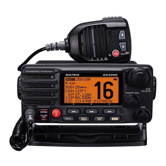
MATRIX GX2000
MATRIX SERIES
GX2000 and GX2150
Owner's Manual
25 Watt VHF/FM
Marine Transceivers
MATRIX AIS+ GX2150
Advertisement
Table of Contents

Related Manuals for Standard Horizon MATRIX Series


Summary of Contents for Standard Horizon MATRIX Series
- Page 1 MATRIX SERIES GX2000 and GX2150 25 Watt VHF/FM Marine Transceivers Owner's Manual GX2000: AIS support with external AIS receiver or transponder GX2150: Integrated dual channel AIS (Automatic Identification System) receiver GX2150: 4800 or 38400 NMEA baud rate selection for plotters with 1 NMEA port GX2150: Able to use PA or Fog signaling when on AIS display True and Magnetic bearing selection on AIS display...
-
Page 2: Table Of Contents
TABLE OF CONTENTS 8.11.3 Fog Signal Timing Chart ..........43 Quick Reference Guide ................4 8.12 INTERCOM OPERATION ............44 1 GENERAL INFORMATION ..............5 8.12.1 Communication ..............44 2 PACKING LIST ..................6 8.12.2 Calling ................44 3 OPTIONAL ACCESSORIES ..............6 8.13 VOICE SCRAMBLER ..............45 4 ONLINE WARRANTY REGISTRATION (in USA or Canada only) ..6 8.14 DEMO MODE ................46 5 GETTING STARTED................7 5.1 PROHIBITED COMMUNICATIONS ..........7... - Page 3 TABLE OF CONTENTS 10.3 DIMMER ADJUSTMENT............90 18 WARRANTY..................131 10.4 DISPLAY CONTRAST ...............90 19 RESET PROCEDURES ..............135 10.5 TIME OFFSET ................91 19.1 MEMORY CLEAR ..............135 10.6 TIME AREA ................91 19.2 MICROPROCESSOR RESETTING ........135 10.7 TIME DISPLAY................91 20 SPECIFICATIONS ................136 10.8 UNIT OF MEASURE ..............91 20.1 GENERAL .................136 10.9 MAGNETIC ................92 20.2 TRANSMITTER .................136...
-
Page 4: Quick Reference Guide
uick efeRence uide The GX2000 and GX2150 are equipped with the E2O (Easy-To-Operate) system. Basic operation may be accomplished by following the procedure below: Press and hold the PWR/VOL knob to turn on or off the radio. Rotate the PWR/VOL knob to adjust the speaker audio volume. Rotate the CH knob (or press the microphone’s keys) to select the operating channel. Move the SQL knob clockwise to squelch or counter clockwise to un-squelch the radio. -
Page 5: General Information
1 GENERAL INFORMATION The STANDARD HORIZON MATRIX Series GX2000 and GX2150 Marine VHF/FM Marine transceiver are designed to be used in USA, International, and Canadian Marine bands. The GX2000 and GX2150 can be operated from 11 to 16 VDC and have a switchable RF output power of 1 watt or 25 watts. MATRIX AIS+ GX2150 Integrates a dual channel AIS (Automatic Identification System) receiver to display AIS vessel information (MMSI, Call Sign, Ship Name, BRG, DST, SOG and COG) directly on the VHF radio, so you will know what is out there in any conditions. The GX2150 is also capable of entering and saving up to... -
Page 6: Packing List
2 PACKING LIST When the package containing the transceiver is first opened, please check it for the following contents: GX2000 or GX2150 Transceiver Power Cord Mounting Bracket and Hardware Owner’s Manual DSC Warning Sticker Flush Mount Template 3 OPTIONAL ACCESSORIES MMB-84 ................Flush-Mount Bracket CMP31B/W ....Remote-Access Microphone (RAM3+ Mic, Black/White) CT-100 ..........23 Feet Extension Cable for RAM3+ Mic CVS2500 ................Voice Scrambler MLS-310 . -
Page 7: Getting Started
5 GETTING STARTED PROHIBITED COMMUNICATIONS The FCC prohibits the following communications: • False distress or emergency messages: • Messages to “any boat” except in emergencies and radio tests; • Messages to or from a vessel on land; • Transmission while on land; • Obscene, indecent, or profane language (potential fine of $10,000). ABOUT VHF RADIO The radio frequencies used in the VHF marine band lie between 156 and 158 MHz with some shore stations available between 161 and 163 MHz. The marine VHF band provides communications over distances that are essen- tially “line of sight” (VHF signals do not travel well through objects such as buildings, hills or trees). Actual transmission range depends much more on antenna type, gain and height than on the power output of the transmitter. -
Page 8: Coaxial Cable
COAXIAL CABLE VHF antennas are connected to the transceiver by means of a coaxial cable – a shielded transmission line. Coaxial cable is specified by it’s diameter and construction. For runs less than 20 feet, RG-58/U, about 1/4 inch in diameter is a good choice. For runs over 20 feet but less than 50 feet, the larger RG-8X or RG-213/U should be used for cable runs over 50 feet RG-8X should be used. For installation of the connector onto the coaxial cable refer to the figure below. -
Page 9: Calling Another Vessel (Channel 16 Or 9)
6. Report the number of persons aboard and condition of any injured. 7. Estimate the present seaworthiness and condition of your vessel. 8. Give your vessel’s description: length, design (power or sail), color and other distinguishing marks. The total transmission should not exceed 1 minute. 9. End the message by saying “OVER”. Release the microphone button and listen. 10. If there is no answer, repeat the above procedure. If there is still no response, try another channel. -
Page 10: Making Telephone Calls
the mic and saying “go to,” the number of the other channel, say “over” and release the PTT button on the mic. Then switch to the new channel. When the new channel is not busy, call the other vessel. After a transmission, say “over,” and release the microphone’s push-to-talk (PTT) switch. When all communication with the other vessel is completed, end the last transmission by stating your Call Sign and the word “out.” Note that it is not necessary to state your Call Sign with each transmission, only at the beginning and end of the contact. Remember to return to Channel 16 when not using another channel. Some radios automatically monitor Channel 16 even when set to other channels or when scanning. MAKING TELEPHONE CALLS To make a radiotelephone call, use a channel designated for this purpose. The fastest way to learn which channels are used for radiotelephone traffic is to ask at a local marina. Channels available for such traffic are designated Public Correspondence channels on the channel charts in this manual. -
Page 11: Automated Radio Check Service
AUTOMATED RADIO CHECK SERVICE In areas across the country, Sea Tow offers boaters a way to conduct radio checks. To use Sea Tow’s free Automated Radio Check service, simply tune your VHF radio to the appropriate channel for your location and conduct a radio check as you typically would. Upon releasing your radio’s microphone, the system will play an automated message and relay your transmission back to you, thereby letting you know how your signal will sound to other boaters. -
Page 12: What Is The Range For Ais Receivers
5.10 WHAT IS THE RANGE FOR AIS RECEIVERS? Since AIS uses similar frequencies as a marine VHF radio, it has similar radio reception capabilities - which are basically line of sight. This means that the higher the VHF antenna is mounted, the greater the reception area will be. Reception from Class A vessels that are 20 or even 30 miles away on open water is not uncommon as their antennas are mounted high off the water. Class B transponders use lower power for transmissions; therefore you can expect Class B vessels to be acquired when they are 5 to 10 miles away. -
Page 13: Installation
6 INSTALLATION SAFETY / WARNING INFORMATION This radio is restricted to occupational use, work related operations only where the radio operator must have the knowledge to control the exposure conditions of its passengers and bystanders by maintaining the minimum separation distance of 3 feet (1 m). Failure to observe these restrictions will result in exceeding the FCC RF exposure limits. Antenna Installation: The antenna must be located at least 3 feet (1 m) away from passengers in order to comply with the FCC RF exposure requirements. LOCATION The radio can be mounted at any angle. Choose a mounting location that: • is far enough from any compass to avoid any deviation in compass reading due to the speaker magnet • provides accessibility to the front panel controls • allows connection to a power source and an antenna... -
Page 14: Mounting The Radio
MOUNTING THE RADIO 6.3.1 Supplied Mounting Bracket The supplied mounting bracket allows overhead or desktop mounting. Use a 13/64” (5.2 mm) bit to drill the holes to a surface which is more 0.4” (10 mm) thick and can support more than 3.3 lbs (1.5 kg) and secure the bracket with the supplied screws, spring washers, flat washers, and nuts. eSktop ounting verHeaD ounting Page 14 GX2000/GX2150... -
Page 15: Optional Mmb-84 Flush Mount Bracket
6.3.2 Optional MMB-84 Flush Mount Bracket 1. Use the supplied template to mark the location where the rectangular hole is to be cut. Confirm the space behind the dash or panel is deep enough to accommodate the transceiver (at least 6.7” (17 cm) deep). There should be at least 1/2” (1.3 cm) between the transceiver’s heatsink and any wiring, cables or structures. 2. Cut out the rectangular hole and insert the transceiver. 3. Fasten the brackets to the sides of the transceiver with the lock washer screw combination; so that the mounting screw base faces the mounting surface (see illustration below). -
Page 16: Electrical Connections
ELECTRICAL CONNECTIONS CAUTION Reverse polarity battery connections will damage the radio! Connect the power cord and antenna to the radio. Antenna and Power Supply connections are as follows: 1. Mount the antenna at least 3 feet (1 m) away from the radio. At the rear of the radio, connect the antenna cable. The antenna cable must have a PL259 connector attached. RG-8/U coaxial cable must be used if the antenna is 25 feet (7.6 m) or more from the radio. RG58 cable can be used for distances less than 25 feet (7.6 m). -
Page 17: Accessory Cables
ACCESSORY CABLES The image and table below show the wires of the MATRIX Series and the connections to optional devices such as a PA speaker (horn), external speak- er, GPS chart plotter and an AIS receiver or transponder. CAUTION Care must be taken not to touch any of the NMEA wires to positive 12 VDC or the radio may be damaged. When connecting the external speaker or GPS navigation receiver, strip off about 1 inch (2.5 cm) of the specified wire’s insulation, then splice the ends together. 6.5.1 MATRIX GX2000 Connection The GX2000 uses NMEA 0183 protocol to communicate to a GPS chart plot- ter and an AIS device. GPS chart plotter connections are at 4800 baud (default setting) and AIS device signalling is at 38400 baud sometimes called HS (high speed). - Page 18 GX2000 4800 Baud Connections PA Speaker Shield GPS Receiver Radio Wires Plotter Connection Blue: NMEA IN ( ) NMEA OUT ( ) Green: NMEA IN ( ) NMEA OUT ( ) Gray: NMEA OUT ( ) NMEA IN ( ) Brown: NMEA OUT ( ) NMEA IN ( ) Yellow: NMEA-HS IN ( )
- Page 19 GX2000 38400 Baud Connections PA Speaker Shield GPS Receiver Radio Wires Plotter Connection Blue: NMEA IN ( ) No Connection Green: NMEA IN ( ) No Connection Gray: NMEA OUT ( ) NMEA IN ( ) Brown: NMEA OUT ( ) NMEA IN ( ) Yellow: NMEA-HS IN ( ) NMEA-HS OUT ( )
-
Page 20: Matrix Ais+ Gx2150 Connection
6.5.2 MATRIX AIS+ GX2150 Connection The GX2150 uses NMEA 0183 protocol to share coordinates, DSC and AIS information to and from a GPS chart plotter. The GX2150 transfers AIS infor- mation to a GPS chart plotter or PC at 38400 baud (sometimes called HS). GPS and DSC information is transferred between a GPS chart plotter with multiple ports (minimum 2) at 4800 baud (default setting). To connect to a GPS chart plotter which has one NMEA port, the GX2150 may be setup to receive GPS coordinates, send DSC and AIS signals at 38400. Refer to section “10.10 NMEA DATA IN/OUT” for details. - Page 21 GX2150 38400 Baud Connections PA Speaker Shield GPS Receiver Radio Wires Plotter Connection Blue: NMEA IN ( ) NMEA OUT ( ) Green: NMEA IN ( ) NMEA OUT ( ) Gray: NMEA OUT ( ) NMEA IN ( ) Brown: NMEA OUT ( ) NMEA IN ( ) Yellow: NMEA-HS OUT ( )
- Page 22 GPS Connections (4800 baud or 38400 baud) The GX2000/GX2150 can select the NMEA baud rate between “4800 bps” and “38400 bps”. Refer to section “10.10 NMEA DATA IN/OUT” for selection. NMEA INPUT (GPS Information) GX2000/GX2150 can read NMEA-0183 version 2.0 or higher. • • The NMEA 0183 input sentences are GLL, GGA, RMC, GNS, GSA, and GSV (RMC sentence is recommended). • If 4800 baud (default) is selected: a. If there is a selection for “PARITY” select “NONE”. b. The Blue and Green wires of input are at 4800 baud. • If 38400 baud is selected: a. The Blue and Green wires of the GX2150 input are at 38400 baud.
-
Page 23: Checking Gps Connections
CHECKING GPS CONNECTIONS After connections have been made between the GX2000/GX2150 and the GPS, a small satellite icon will appear on the top right corner of the display and your current location (latitude/longitude) is shown on the display. NOTE If there is a problem with the NMEA connection between the radio and the GPS, the GPS icon will blink continuously until the connec- tion is corrected. -
Page 24: Changing The Time Location
CHANGING THE TIME LOCATION This menu selection allows the radio to show UTC time or local time with the offset. key until “ Setup Menu ” 1. Press and hold the CALL MENU appears, then select “ GENERAL SETUP ” with the CH knob. 2. Press the soft key, then rotate the CH knob to “ TIME AREA ”. 3. Press the soft key. 4. Rotate the CH knob to select “... -
Page 25: Changing Cog To True Or Magnetic
6.10 CHANGING COG TO TRUE OR MAGNETIC Allows the GPS COG (Course Over Ground) and the BRG from an AIS target to be selected to show in True or Magnetic. Factory default is “True” however by following the steps below the COG can be changed to “Magnetic”. key until “ Setup Menu ” 1. Press and hold the CALL MENU appears, then select “ GENERAL SETUP ” with the CH knob. 2. Press the soft key, then rotate the CH knob to select “ MAGNETIC ”. 3. Press the soft key. - Page 26 5. Referring to illustration below, make a 1.2” (30 mm) hole in the wall, then insert the extension cable into this hole. Connect the gasket and mount base to the extension cable connector using the nut. 6. Drill the four screw holes (approx. 2 mm) on the wall, then install the mounting base to the wall using four screws. 7. Put the rubber cap on to the nut. The installation is now complete. External Speaker Connections Ferrite Core Gasket Wall Routing Cable Mounting Bracket NOTE Caution!: Before cutting the cable, it must be disconnected from the rear panel of the transceiver.
-
Page 27: Connecting An External Speaker To The Ram3+ Mic Cable
6.11.1 Connecting an External Speaker to the RAM3+ Mic Cable In noisy locations and optional external speaker may be connected to the white speaker wires on the RAM3+ routing cable. The RAM3+ can drive the internal speaker or the external speaker one at a time. When connecting an external speaker, follow the procedure below to turn off the RAM3+ audio and enable the external speaker wires on the RAM3+ routing cable. 1. On the RAM3+ mic, press and hold the key until “... -
Page 28: Controls And Indicators
7 CONTROLS AND INDICATORS NOTE This section defines each control of the transceiver. See illustra- tion at the next page for location of controls. For detailed operating instructions refer to chapter 8 of this manual. FRONT PANEL CH Knob (Channel Selection) Rotary knob is used to select channels and to choose menu items (such as the DSC menu, General Setup and DSC Setup menu). The keys on the microphone can also be used to select channels and menu items. eConDary uSe Press this knob to enter a selection in the setup menu or DSC menu. While holding the soft key and turning this knob, you can confirm memory channels that have been programmed for scanning. -
Page 29: Channels
eConDary uSe When in PA or Fog mode, controls the listen-back volume (GX2150 only). SQL Knob ( Squelch Control ) Adjusting this control clockwise, sets the point at which random noise on the channel does not activate the audio circuits but a received signal does. This point is called the squelch threshold. Further adjustment of the squelch control will degrade reception of wanted transmissions. -
Page 30: Rear Panel
Key Press the key briefly to recall Channel 16 from any channel location. Press and hold the key to recall Channel 9. Pressing the key again reverts to the previous selected working channel. Key DISTRESS Used to send a DSC distress call. To send the distress call refer to section “9.3.1 Transmitting a DSC Distress Call.” REAR PANEL Never remove this rubber cap. - Page 31 P A Speaker Connection Cable ( Red & Shield ) Connects the GX2000/GX2150 to an optional PA speaker. Refer to section “3 OPTIONAL ACCESSORIES” for a list of optional STANDARD HORIZON Speakers. D C Input Cable Connects the radio to a DC power supply capable of delivering 11 to 16V A ccessory Connection Cable ( Blue, Green, Gray, Brown, Yellow & White ) Connects the GX2000/GX2150 to a GPS receiver and AIS receiver (GX2000). Refer to section “6.5 ACCESSORY CABLES”. RAM3+ Connector ( Remote Station Microphone Connector ) Connects the GX2000/GX2150 to the CMP31 ( RAM3+ ) Remote Station Microphone. Refer to section “15 CMP31 ( RAM3+ ) REMOTE MIC...
-
Page 32: Microphone
MICROPHONE PTT Switch ( Push-To-Talk Switch ) When in radio mode and the PTT switch is pressed, the transmitter is enabled for voice communications to another vessel. When PA mode is selected, pressing the PTT switch allows your voice to be amplified and supplied to a connected PA horn. When an optional RAM3+ mic is connected and intercom mode is select- ed, pressing the PTT switch enables voice communications from the GX2000 / GX2150 to the RAM3+ second station mic. -
Page 33: Basic Operation
8 BASIC OPERATION RECEPTION 1. After the transceiver has been installed, ensure that the power supply and antenna are properly connected. 2. Press and hold the PWR/VOL knob until the radio turns on. 3. Rotate the SQL knob fully counterclockwise. This state is known as “squelch off”. 4. Turn up the PWR/VOL knob until noise or audio from the speaker is at a comfortable level. 5. Rotate the SQL knob clockwise until the random noise disappears. This state is known as the “squelch threshold.” 6. Rotate the CH knob to select the desired channel. Refer to the channel chart on page 128 for available channels. -
Page 34: Simplex/Duplex Channel Use
SIMPLEX/DUPLEX CHANNEL USE Refer to the VHF MARINE CHANNEL CHART (page 128) for instructions on use of simplex and duplex channels. NOTE All channels are factory-programmed in accordance with FCC (USA), Industry Canada (Canada), and International regulations. Mode of operation cannot be altered from simplex to duplex or vice-versa. DISPLAY TYPE The GX2000/GX2150 display can be setup to show displays other than the default “NORMAL” VHF display by using the procedure below: key until “ Setup Menu ” 1. Press and hold the CALL MENU appears, then select “ GENERAL SETUP ” with the CH knob. 2. Press the soft key, then rotate the CH knob to select “... -
Page 35: Usa, International, And Canada Mode
NOTE To show position information, show AIS targets and use the compass display: GX2150 - external GPS must be connected. GX2000 - external AIS receiver or transponder and an external GPS must be connected. USA, INTERNATIONAL, AND CANADA MODE To change the channel group from USA to International or Canada: key until “ Setup 1. Press and hold the CALL MENU Menu ” appears. 2. Rotate the CH knob to select “ CH FUNCTION SETUP ”. 3. Press the soft key, then rotate the CH knob to select “... -
Page 36: Noaa Weather Alert Testing
The GX2000/GX2150 can receive weather alerts when on a weather channel and on the last selected weather channel during scanning modes or while on another channel. When an alert is received on a NOAA weather chan- nel, scanning will stop and the transceiver will emit a loud beep to alert the user of a NOAA broadcast. Press any key to stop the alert and receive the weath- er report. Press the soft key to return to the last selected channel. -
Page 37: Scanning
NOTE The priority channel may be changed from CH16 to another channel. Refer to section “11.5 PRIORITY CHANNEL”. SCANNING The GX2000/GX2150 will automatically scan channels programmed into the preset channel memory and also the scan channel memory, and the last selected weather channel. When an incoming signal is detected on one of the channels during scan, the radio will pause on that channel, allowing you to listen to the incoming trans- mission. The radio will automatically start scanning again after the transmis- sion stops. 8.9.1 Selecting the Scan Type key until “ Setup 1. Press and hold the CALL MENU Menu ” appears. 2. Rotate the CH knob to select “ CH FUNCTION SETUP ”. soft key, then select “... -
Page 38: Programming Scan Memory
8.9.2 Programming Scan Memory key until “ Setup Menu ” 1. Press and hold the CALL MENU appears. 2. Rotate the CH knob to select “ CH FUNCTION SETUP ”. soft key, then rotate the CH 3. Press the knob to select “ SCAN MEMORY CH ”. 4. Press the soft key. -
Page 39: Priority Scanning (P-Scan)
8.9.4 Priority Scanning (P-SCAN) In the default setting, Channel 16 is set as the priority channel. You may change the priority channel to the desired channel from Channel 16 by the General Setup mode, refer to section “11.5 PRIORITY CHANNEL”. 1. Adjust the SQL knob until background noise disappears. 2. Press one of the soft key, then press the soft key. “ P-SCAN ” appears on the display. Scan- ning will proceed between the memorized chan- nels and preset channel (described in next section) and the priority channel. -
Page 40: Operation
8.10.2 Operation 1. Press one of soft keys, then press the soft PRESET key to recall the preset channel. The “P SET” icon will appear on the display. 2. Rotate the CH knob to select the desired preset channel (“0” ~ “9”). The preset channel number appears (“ P-SET0 ” - “ P-SET9 ”) while selecting the preset channel. 3. Press one of soft keys, then press the soft PRESET key to return to the last selected channel. The “P SET” icon will disappear from the display. 8.10.3 Deletion 1. Press one of soft keys, then press the soft... -
Page 41: Pa/Fog Operation
8.11 PA/FOG OPERATION The GX2000/GX2150 has a 30W hailer built-in and can be used with any 4 Ohm PA horn. Standard Horizon offers two HAIL/PA horns, the 220SW (5” round 30 Watt HAIL/PA horn) and the 240SW (5” x 8” rectangular 40 Watt HAIL/PA horn). When the GX2150 is in PA Hail mode the PA speaker listens back (acts as a microphone and provides two-way communications through the PA horn to the main radio). NOTE When in the PA HAIL or FOG HORN mode, the GX2000/GX2150 will continue to receive DSC calls and communications on the last selected working channel prior to entering the PA HAIL or FOG HORN mode. -
Page 42: Operating The Fog Horn Mode
4. To listen back (GX2150 only), rotate the PWR/VOL knob. 5. To exit the PA HAIL mode, press the key. NOTE When in the PA HAIL mode it is possible to simultaneously use the AIS page by pressing the key. 8.11.2 Operating the FOG HORN mode The user can select the type of horn from “Underway”, “Stop”, “Sail”, “Tow”, “Aground”, “Anchor”, “Horn”, and “Siren”. 1. Press one of the soft keys, then press the PA/FOG soft key. Note: The soft key may have to be pressed to see the soft key if the soft keys PA/FOG have not be customized. 2. Rotate the CH knob to select “ FOG ”, then press soft key. -
Page 43: Fog Signal Timing Chart
8.11.3 Fog Signal Timing Chart TYPE PATTERN USAGE UNDERWAY One 5-second blasts every 120 seconds. Motor vessel underway and making way. Listen Back 120s STOP Two 5-second blasts (separated by 2 seconds) Motor vessel underway but every 120 seconds. stopped (not making way). Listen Back 120s SAIL One 5-second blasts followed by two 1-second S a i l i n g v e s s e l u n d e r w a y, blasts (separated by 2 seconds) every 120 fishing vessel (underway or seconds. -
Page 44: Intercom Operation
8.12 INTERCOM OPERATION To access the following intercom functions one of the soft keys must be setup as “IC”. Refer to section “10.14 SOFT KEYS”. In addition an optional RAM3+ remote station microphone (e.g. CMP31) must be connected to perform intercom functions between the GX2000/ GX2150 and the RAM3+. 8.12.1 Communication 1. Press one of the soft keys, then press the soft key to enable the intercom mode. -
Page 45: Voice Scrambler
8.13 VOICE SCRAMBLER If privacy of communications is desired, a CVS2500 4-code voice scram- bler (VS) can be installed in the transceiver. Contact your Dealer to have a CVS2500 installed. Refer to the section “11.9 SCRAMBLER SETUP” to program the voice scrambler. 1. Select a channel that was programmed for scrambler mode (“... -
Page 46: Demo Mode
8.14 DEMO MODE This mode is used by Standard Horizon sales persons and dealers to demonstrate radio, DSC and AIS functions. Demo mode allows latitude, longitude and time to be entered to simulate radio displays. When the demo mode is enabled, the radio display will automatically switch from the NORMAL, COMPASS, AIS and WAYPOINT displays. -
Page 47: Digital Selective Calling (Dsc)
9 DIGITAL SELECTIVE CALLING (DSC) GENERAL WARNING This GX2000/GX2150 is designed to generate a digital maritime distress and safety call to facilitate search and rescue. To be effective as a safety device, this equipment must be used only within commu- nication range of a shore-based VHF marine channel 70 distress and safety watch system. The range of signal may vary but under normal conditions should be approximately 20 nautical miles. NOTE A DSC Warning sticker is included with WARNING STICKER the GX2000/GX2150. To comply with FCC regulations this sticker must be mounted in a location that can be easily viewed from the location of the GX2000/ GX2150. -
Page 48: Programming The Mmsi
THIS NUMBER MUST BE PROGRAMMED INTO THE RADIO TO OPER- ATE DSC FUNCTIONS. How can I obtain an MMSI assignment? In the USA, visit the following websites to register: http://www.boatus.com/mmsi/ http://seatow.com/boating_safety/mmsi.asp http://www.usps.org/php/mmsi/rules.php In Canada, visit http://www.ic.gc.ca/epic/site/smt-gst.nsf/en/sf01032e.html 9.2.2 Programming the MMSI WARNING The MMSI can be inputted only once. Therefore please be care- ful not to input the incorrect MMSI number. If you need to change the MMSI number after it has been entered, the radio will have to be returned to Factory Service. Refer to the section “16.2 FACTORY... -
Page 49: Dsc Distress Call
8. After the second number has been input, -User MMSI- press and hold the CH knob to store the Stored ID 123456789 MMSI. 9. Press the soft key to return to radio operation. NOTE To view your MMSI after programming to ensure it is correct, perform steps 1~3. Look that the MMSI number shown on the display is correct. - Page 50 4. W h e n a D S C d i s t r e s s a c k n o w l e d g m e n t i s !DISTRESS ALERT! Nature of:Undesignated received, a distress alarm sounds and Channel Position: 33 37.120 118 09.580...
- Page 51 Transmitting a DSC Distress Alert with Manual Position of Input When the GX2000/GX2150 is not connected to a GPS receiver, you may input the latitude and longitude of your vessel manually before you send a DSC distress alert. key. The “ D S C M e n u ” will 1. Press the CALL MENU...
-
Page 52: Receiving A Dsc Distress Call
Canceling a DSC Distress Call If a DSC distress call was sent by error the GX2000/GX2150 allows you to send a message to other vessels to cancel the distress call that was made. Press the soft key, then press the soft key. !DISTRESS ALERT! Nature of:Undesignated Position: 33 37.120 118 09.580 POS Time: 10:00 TX in: 02:25 Wait for ACK PAUSE CANCEL 9.3.2 Receiving a DSC Distress Call... - Page 53 5. When you finish entering the waypoint name, press and hold the soft key to replace the display to the waypoint screen. The display indi- cates the distance and direction of the distressed vessel, and also the compass indicates the distressed vessel by dot ( ) . 6. To stop navigating to a waypoint, press one of the soft keys, then press the soft key. The...
-
Page 54: All Ships Call
ALL SHIPS CALL The all ships call function allows contact to be established with DSC equipped vessels without having their MMSI in the individual calling direc- tory. Also, priority for the call can be designated as “Urgency” or “Safety”. URGENCY Call: This type of call is used when a vessel may not truly be in distress, but have a potential problem that may lead to a distress situation. This call is the same as saying “PAN PAN, PAN PAN, PAN PAN” on Channel 16. -
Page 55: Receiving An All Ships Call
9.4.2 Receiving an All Ships Call 1. When an all ships call is received, an emergency Received All Ships Name:Horizon alarm will sound. ID:123456789 Category:Safety CH: 06 The display shows the MMSI of the vessel trans- Since: 01:03 mitting the all ships call and the radio will change ACCEPT PAUSE QUIT Received All Ships to the requested channel after 10 seconds. Name:Horizon ID:123456789 2. Press any key to stop the alarm. Category:Safety CH: 06 3. Monitor the requested channel until the all ships... -
Page 56: Individual Call
INDIVIDUAL CALL This feature allows the GX2000/GX2150 to contact another vessel with a DSC VHF radio and automatically switch the receiving radio to a desired communications channel. This feature is similar to calling a vessel on CH16 and requesting to go to another channel (switching to the channel is private between the two stations). Up to 80 individual contacts may be programmed. 9.5.1 Setting up the Individual / Position Call Directory The GX2000/GX2150 has a DSC directory that allows you to store a vessel or person’s name and the MMSI (Maritime Mobile Service Identity Number) number associated with vessels you wish to transmit individual calls, auto polling, position request, position report, and polling transmissions. -
Page 57: Setting Up The Individual Call Reply
If a mistake was made entering in the name repeat pressing the soft key until the wrong character is selected, then rotate the CH knob to correct the entry. 9. After the eleventh letter or space has been entered, press and hold the soft key to advance to the MMSI number entry. 10. Rotate the CH knob to scroll through -Individual Directory- numbers, 0-9. To enter the desired number Individual Name Horizon and move one space to the right by pressing ID:123456789 soft key. Repeat this procedure BACK QUIT until all nine space of the MMSI number are entered. -
Page 58: Enabling The Individual Call Acknowledgment
9.5.3 Enabling the Individual Call Acknowledgment The radio can select either reply message “Able” (default) or “Unable” when the individual reply setting (described in the previous section) is set to “AUTOMATIC”. key until “ Setup 1. Press and hold the CALL MENU Menu ” appears. 2. Rotate the CH knob to select “ DSC SETUP ” menu. 3. Press the soft key, then select -DSC Setup- “... - Page 59 7. When an individual call acknowledgment is received, the established channel is automatically changed to the channel which is selected on step 5 above and a ringing tone sounds. 8. Press the soft key to listen to the channel to make sure it is not busy, then press the microphone’s PTT switch and talk into the microphone to the other vessel.
-
Page 60: Receiving An Individual Call
12. Press the soft key to listen to the channel to make sure it is not busy, then press the microphone’s PTT switch and talk into the microphone to the other vessel. 9.5.5 Receiving an Individual Call When an individual DSC call is received, the radio will automatically respond (default setting) to the calling ship, and switch to the requested channel for voice communications. Refer to section “9.5.2 Setting up the Individual Call Reply” to change the reply to manual if you want to see who is calling before replying to the call. -
Page 61: Setting Up The Individual Call Ringer
: Press this key to temporarily disable automatic switching to the requested channel. Note: In some cases automatically switching to a requested chan- nel might disrupt import ongoing communications. This feature allows commercial users to suspend channel switching and stay on the working channel selected before the all ships call was received. : Press this key to quit the automatic channel switching and revert to the last selected working channel. 4. Press the key to return to the channel display. NOTE When there is an unread individual call, “ ” icon will appear on the display. You may review the unread individual call from the DSC log, refer to the section “9.13.3 Reviewing Other Logged Calls.” 9.5.6 Setting up the Individual Call Ringer When an individual call is received the radio will produce a ringing sound for 2 minutes. This selection allows the individual call ringer time to be changed. - Page 62 The GX2000/GX2150 has the capability to turn off the individual call ringer. key until “ Setup 1. Press and hold the CALL MENU Menu ” appears. 2. Rotate the CH knob to select “ DSC SETUP ” menu. soft key, then select “ DSC 3. Press the BEEP ” with the CH knob. 4. Press the soft key. 5. Rotate the CH knob to select “ Individual ”, -DSC Beep- then press the soft key.
-
Page 63: Group Call
GROUP CALL This feature allows the user to contact a group of specific vessels (e.g. members of a yacht club) using DSC radios with group call function to auto- matically switch to a desired channel for voice communications. This func- tion is very useful for yacht clubs and vessels traveling together that want to collectively make announcements on a predetermined channel. Up to 32 group MMSIs may be programmed. - Page 64 key until “ Setup 1. Press and hold the CALL MENU Menu ” appears. 2. Rotate the CH knob to select “ DSC SETUP ” menu. 3. Press the soft key, then select -DSC Setup- “ GROUP DIRECTORY ” with the CH knob. Individual Directory Individual Reply soft key, then select “ ADD ” 4. Press the Individual Ack Individual Ring with the CH knob.
-
Page 65: Transmitting A Group Call
9.6.2 Transmitting a Group Call Group Call using the Group Directory key. The “ DSC Menu ” will 1. Press the CALL MENU appear. 2. Rotate the CH knob to select “ GROUP ”. (To cancel, press the soft key.) 3. Press the soft key. The transceiver will beep, and the last group calls will appear. - Page 66 Group Call by Manually Entering an MMSI This feature allows you to contact a group of vessels by entering in their group MMSI manually. key. The “ DSC Menu ” will 1. Press the CALL MENU appear. 2. Rotate the CH knob to select “ GROUP ”. (To cancel, press the soft key.) 3. Press the...
-
Page 67: Receiving A Group Call
9.6.3 Receiving a Group Call 1. When a group call is received, the GX2000/ GX2150 will produce a ringing alarm sound. 2. The display shows the group MMSI number. 3. Press any key to stop the alarm. 4. Monitor the channel for the person calling the group for a message. On the display you will notice 3 soft key selections. These selections are described below: : Press this key to accept the group call and to switch to request- ed channel. Note: If a key is not pressed for 30 seconds or longer the radio will auto- matically change to the requested channel. : Press this key to temporarily disable automatic switching to the requested channel. : Press this key to quit the automatic channel switching and revert to the last selected working channel. 5. If you want to respond, monitor the channel to make sure it is clear, then press the microphone’s PTT switch and talk into the microphone to the group of vessels. -
Page 68: Setting Up The Group Call Ringer
9.6.4 Setting up the Group Call Ringer The GX2000/GX2150 has the capability to turn off the group call ringer. key until “ Setup 1. Press and hold the CALL MENU Menu ” appears. 2. Rotate the CH knob to select “ DSC SETUP ” menu. soft key, then select “ DSC 3. Press the BEEP ” with the CH knob. 4. Press the soft key. 5. Rotate the CH knob to select “ Group ”, then press the soft key. -
Page 69: Position Request
POSITION REQUEST Advancements in DSC have made it possible to poll the location of another vessel and show the position of that vessel on the display of the GX2000/ GX2150. Standard Horizon has taken this feature one step further, if any compatible GPS chart plotter is connected to the GX2000/GX2150, the polled position of the vessel is shown on the display of the GPS chart plot- ter making it easy to navigate to the location of the polled vessel. This is a great feature for anyone wanting to know the position of another vessel. For example your buddy that is catching fish, or finding the location of a person... -
Page 70: Transmitting A Position Request To Another Vessel
5. Press the soft key to store the selected setting. 6. Press the soft key two times to return to radio operation. 9.7.2 Transmitting a Position Request to Another Vessel Position Request using the Individual/Position Directory key. The “ DSC Menu ” will 1. Press the CALL MENU appear. 2. R o t a t e t h e C H k n o b t o s e l e c t “ P O S REQUEST ”, then press the soft key. -
Page 71: Receiving A Position Request
4. Rotate the CH knob to select “ MANUAL ,” then press the soft key. 5. Rotate the CH knob to select the first number of the MMSI (nine digits) which you want to contact, then press the soft -POS Request Call- key to step to the next number. Input MMSI 6. Repeat step 5 to set the MMSI number. ID:--------- If a mistake was made entering in the MMSI -POS Request Call- SELECT BACK QUIT number, repeatedly press the soft Input MMSI ID:345678901... -
Page 72: Setting Up A Position Request Ringer
Manual reply: 1. When a position request call is received from Received POS Request Name:Horizon another vessel, the display will be as shown in ID:123456789 Category:Routine the illustration at the right. Since: 01:03 2. A ringing alarm sounds 4 times. To send your REPLY QUIT vessels position to the requesting vessel, press Received POS Request... -
Page 73: Position Report
POSITION REPORT The feature is similar to position request, however instead of requesting a position of another vessel this function allows you to send your position to another vessel. Your vessel must have an operating GPS receiver connected to the GX2000/GX2150 to send the position. NOTE To transmit a position report call, a GPS must be connected to the radio and the GX2000/GX2150 individual directory must be programmed with stations you wish to send your position to. To setup this directory refer to section “9.5.1 Setting up the Individual / Posi-... -
Page 74: Receiving A Dsc Position Report Call
DSC Position Report Call Manually Entering an MMSI This feature allows you to send your position to another vessel by manually entering the MMSI of the ship you want to send your position to. key. The “ DSC Menu ” will 1. Press the CALL MENU appear. 2. Rotate the CH knob to select “ POS REPORT ”. (To cancel, press the soft key.) 3. Press the soft key. The transceiver will beep, and the POS report call menu will appear. -POS Report Call- 4. Rotate the CH knob to select “ MANUAL ”, Input MMSI then press the soft key. -
Page 75: Navigating To A Position Report
9.8.3 Navigating to a Position Report The GX2000/GX2150 has a feature that allows navigation to a received posi- tion report call by using the compass display. Navigating to the position of a position report call may be enabled by the procedure below. 1. After the position report call has been Received POS REPORT Name:Horizon received, press the soft key. ID:123456789 Category:Routine 2. To start navigating using the compass Since: 01:03 -Waypoint Input- -POS INFO-... -
Page 76: Saving A Position Report As A Waypoint
9.8.5 Saving a Position Report as a Waypoint The GX2000/GX2150 can save a position report call in the radio’s memory as a waypoint. 1. After the position report call has been Received POS REPORT Name:Horizon received, press the soft key. ID:123456789 Category:Routine 2. Rotate the CH knob to change the first Since: 01:03 -POS INFO- letter in the name of the waypoint and press TO WPT SAVE... -
Page 77: Setting Up A Position Report Ringer
9.8.7 Setting up a Position Report Ringer The GX2000/GX2150 has the capability to turn off the position report ringer. key until “ Setup 1. Press and hold the CALL MENU Menu ” appears. 2. Rotate the CH knob to select “ DSC SETUP ” menu. soft key, then select “ DSC 3. Press the BEEP ” with the CH knob. soft key, then select “ POS 4. Press the Report ” with the CH knob. soft key, then select “... -
Page 78: Manual Input Of A Gps Location (Lat/Lon)
MANUAL INPUT OF A GPS LOCATION (LAT/LON) You may send the latitude and longitude of your vessel manually even if the GX2000/GX2150 is not connected the GPS receiver unit. After the position is entered, transmitting a DSC distress, position request, or position report will contain the manually entered position. key until “ Setup 1. Press and hold the CALL MENU Menu ” appears. 2. Rotate the CH knob to select “ DSC SETUP ” menu. 3. Press the soft key, then select “ POSITION INPUT ” with the CH knob. 4. Press the soft key. The transceiver will beep, and the display will be as shown... -
Page 79: Auto Pos Polling
9.10 AUTO POS POLLING The GX2000/GX2150 has the capability to automatically track four stations programmed into the individual directory. The following procedure allows the time interval between position requests to be setup. 9.10.1 Setting up the Polling Time Interval key until “ Setup 1. Press and hold the CALL MENU Menu ” appears. 2. Rotate the CH knob to select “... -
Page 80: Enabling/Disabling Auto Pos Polling
5. T h e r a d i o w i l l s h o w t h e s t a t i o n s programmed in the individual directory. Rotate the CH knob to select the desired -Auto POS Polling- CALL 1:HORIZON station and press the... -
Page 81: Dsc Test
9.11 DSC TEST This function is used to contact another DSC equipped vessel to ensure the DSC functions of the radio are operating. NOTE To use this feature, the radio you will be transmitting the test call to needs to have the DSC Test feature. To perform the DSC test you will need to enter a MMSI of another vessel into the individual directory or manually enter in the MMSI using the procedure below. 9.11.1 Programming MMSI into Individual Directory Refer to section “9.5.1 Setting up the Individual / Position Call Directory”. 9.11.2 DSC Test call by using Individual/Position Directory key. The “... -
Page 82: Dsc Test Call By Manually Entering An Mmsi
9.11.3 DSC Test Call by Manually Entering an MMSI key. The “ DSC Menu ” will 1. Press the CALL MENU appear. 2. Rotate the CH knob to select “ DSC TEST ”, then press the soft key. 3. Rotate the CH knob to select “ MANUAL ” and press the soft key. -
Page 83: Polling Call
9.12 POLLING CALL The GX2000/GX2150 has the capability to track another vessel. 9.12.1 Transmitting a Polling Call to Another Vessel Polling Call using the Individual/Position Call Directory key. The “ DSC Menu ” will 1. Press the CALL MENU appear. 2. Rotate the CH knob to select “ POLLING ”, then press the soft key. -
Page 84: Receiving A Polling Call
Polling Call by Manually Entering an MMSI This feature allows you to contact a vessel by manually entering the MMSI of the ship you want to track. key. The “ DSC Menu ” will 1. Press the CALL MENU appear. 2. Rotate the CH knob to select “ POLLING ”, then press the soft key. 3. Rotate the CH knob to select “ MANUAL ” and press the soft key. -
Page 85: Dsc Log Operation
9.13 DSC LOG OPERATION The GX2000/GX2150 logs transmitted calls, received DSC distress calls, and other calls (individual, group, all ships, etc.). The DSC log feature is similar to an answer machine where calls are recorded for review and a “ ” icon will appear on the radios display. The GX2000/GX2150 can store up to 24 transmitted calls, up to the latest 27 distress calls, and up to the latest 64 other calls (individual, group, all ships, position report, position request ack, test call ack, and polling calls). NOTE When the “ DSC LOG ” menu is selected, the GX2000/GX2150 may display high-priority logged call automatically. -
Page 86: Reviewing A Logged Dsc Distress Call
9.13.2 Reviewing a Logged DSC Distress Call The GX2000/GX2150 radios allow logged DSC distress call to be reviewed. key. The “ D S C M e n u ” will 1. Press the CALL MENU appear. 2. Rotate the CH knob to select “ DSC LOG ” menu. 3. Press the soft key, then rotate the CH knob to select “... -
Page 87: Reviewing Other Logged Calls
9.13.3 Reviewing Other Logged Calls key. The “ DSC Menu ” will 1. Press the CALL MENU appear. 2. Rotate the CH knob to select “ DSC LOG ” menu. 3. Press the soft key, then rotate the CH knob to select “ OTHER CALL LOG ”. -DSC Log- Transmitted Log 4. Press the... - Page 88 2) If you want to delete “a ” “v ” eLete o n e o f t h e l o g g e d -Distress Log- 08:15 234567891 stations, select the 06:36 Pamle 18:42 SUN LIGHT “ V I E W L O G L I S T ” w i t h t h e C H k n o b , DELETE QUIT...
-
Page 89: General Setup
10 GENERAL SETUP The optional CMP31 ( RAM3+ ) Remote Station Microphone can also change the setup menu using the following procedure. 10.1 DISPLAY The GX2000/GX2150 can select additional screens other than the default normal (radio) display. Refer to section “8.5 DISPLAY TYPE” for details. 10.2 LOCAL DISTANCE RECEIVER ATTENUATOR In some areas, signals from external sources may cause interference to receiving marine transmissions. The GX2000/GX2150 has two selections, “Distance” - used to receive weak signals (default), and “Local” - which atten- uates strong signals that may be interfering with reception. -
Page 90: Dimmer Adjustment
10.3 DIMMER ADJUSTMENT This menu selection adjusts the backlight intensity. key until “ Setup Menu ” 1. Press and hold the CALL MENU appears. 2. Rotate the CH knob to select “ GENERAL SETUP ” menu. soft key, then select “ DIMMER ” 3. Press the with the CH knob. 4. Press the soft key. -
Page 91: Time Offset
10.5 TIME OFFSET Sets the local time offset between UTC (Universal Time Coordinated) and local time shown on the display. The offset is added or subtracted from the time received from the GPS or chart plotter. Time is only displayed when a GPS or chart plotter is connected. -
Page 92: Magnetic
7. Press the soft key to store the selected level. 8. Press the soft key three times to return to radio operation. 10.9 MAGNETIC This selection allows customizing the GPS COG (Course Over Ground) indi- cation on the normal and compass pages and BRG on the waypoint and AIS pages. Refer to section “6.10 CHANGING COG TO TRUE OR MAGNETIC” for details. NOTE A GPS must be connected to the radio to be able to show COG. 10.10 NMEA DATA IN/OUT This menu is used to setup the NMEA 0183 baud rate of the GPS input (Blue and Green wires) and DSC output (Gray and Brown wires). The default setting is 4800 bps. -
Page 93: Key Beep
10.11 KEY BEEP This selection is used to select the beep tone volume level when a key is pressed. key until “ Setup Menu ” 1. Press and hold the CALL MENU appears. 2. Rotate the CH knob to select “ GENERAL SETUP ” menu. 3. Press the soft key, then rotate the CH knob to select “... -
Page 94: Station Name
key until “ Setup Menu ” 1. Press and hold the CALL MENU appears. 2. Rotate the CH knob to select “ GENERAL SETUP ” menu. 3. Press the soft key, then rotate the CH knob to select “ FOG FREQUENCY ”. 4. Press the soft key. 5. Rotate the CH knob to select the desired tone frequency. -
Page 95: Soft Keys
8. Repeat step 6 and 7 until the name is complete. The name can consist of up to eight characters, if you do not use all eight characters press the soft key to move to the next space. This method can also be used to enter a blank space in the name. If a mistake was made entering in the name repeatedly press the soft key until the wrong character is selected, then rotate the CH knob to correct the entry. - Page 96 9. Press the key, then rotate the CH knob to select “ KEY TIMER ” (selects how long the soft key icon will be shown on the display after a soft key is pressed, default is 5 seconds). Then, press the soft key. 10. Rotate the CH knob to select the time. 11. Press the soft key to store the selected setting. 12. Press the soft key three times to return to radio operation. DISPLAY FUNCTION DIMMER Select the menu for the display and key back light intensity SCAN Starts and stops scanning.
-
Page 97: Channel Function Setup
11 CHANNEL FUNCTION SETUP 11.1 CHANNEL GROUP This section selects a channel group from USA, Canada, and International. Refer to section “8.6 USA, CANADA, AND INTERNATIONAL MODE” for details. 11.2 SCAN MEMORY To be able to scan channels the radio must be programmed. This section allows channels to be stored in scan memory. Refer to section “8.9.2 Programming Scan Memory” for details. 11.3 SCAN TYPE This selection is used to select the scan mode between “Memory Scan” and “Priority Scan”. The default setting is “Priority Scan”. -
Page 98: Priority Channel
11.5 PRIORITY CHANNEL By default the radio priority channel is set to Channel 16. This procedure allows the radio to use a different priority channel used when priority scan- ning. key until “ Setup Menu ” 1. Press and hold the CALL MENU appears. 2. Rotate the CH knob to select “ CH FUNCTION SETUP ”. soft key, then select “ PRIORITY 3. Press the CH ”... -
Page 99: Channel Name
11.7 CHANNEL NAME When radio (“Normal”) mode is selected, the display will show a name under the channel number. This name describes the use of the channel. The radio has the capability to customize the name by the procedure below. Example: CH69 PLEASURE to HOOKUP key until “ Setup Menu ” 1. Press and hold the CALL MENU appears. 2. Rotate the CH knob to select “ CH FUNCTION SETUP ”. soft key, then select “ CH NAME ” 3. Press the with the CH knob. 4. Press the soft key. -
Page 100: Scrambler Setup
11.8 SCRAMBLER SETUP NOTE Operates only when the optional CVS2500 is installed. This menu will not appear unless a CVS2500 is installed. key until “ Setup Menu ” 1. Press and hold the CALL MENU appears. 2. Rotate the CH knob to select “ CH FUNCTION SETUP ”. soft key, then select “... -
Page 101: Dsc Setup
12 DSC SETUP 12.1 INDIVIDUAL DIRECTORY The GX2000/GX2150 has a DSC directory that allows you to store a vessel or person’s name and the MMSI number associated with vessels you wish to transmit individual calls, position requests and position report transmissions. To transmit an individual call you must program this directory with information of the persons you wish to call, similar to a cellular phones telephone directory. Refer to section “9.5.1 Setting up the Individual / Position Call Directory” for details. 12.2 INDIVIDUAL REPLY This menu item sets up the radio to automatically (default setting) or manu- ally respond to a DSC Individual call requesting you to switch to a working channel for voice communications. When “Manual” is selected the MMSI of the calling vessel is shown allowing you to see who is calling. This function is similar to caller id on a cellular phone. -
Page 102: Position Reply
12.6 POSITION REPLY The GX2000/GX2150 can be set up to automatically (default setting) or manually send your position when requested by another vessel. This selec- tion is important if you are concerned about someone polling the position of your vessel that you may not want to. In the manual mode you will see the MMSI or persons name shown on the display allowing you to choose to send your position to the requesting vessel. Refer to section “9.7.1 Setting up a Position Request Reply” for details. 12.7 DSC BEEP This feature allows the alarm beeps to be turned on (default setting) or off when a DSC call is received. The DSC calls that can be customized are: individual, group, all ships, position request, and position report. -
Page 103: Auto Channel Switch Time
12.8 AUTO CHANNEL SWITCH TIME When a DSC distress or an all ships (urgency or safety) call is received, the GX2000/GX2150 will automatically switch to Channel 16. This menu selection allows the automatic switch time to be changed. The default selection is 30 seconds. key until “ Setup Menu ” 1. Press and hold the CALL MENU appears. 2. Rotate the CH knob to select “ DSC SETUP ”. soft key, then select “ AUTO CH 3. Press the SWITCH TIME ”... -
Page 104: Action Timer On Dsc Operation
12.10 NO ACTION TIMER ON DSC OPERATION If a key is not pressed during the DSC operation, the GX2000/GX2150 will automatically return to radio operation. This menu selection allows the automatic switch time to be changed. The default selection is 15 minutes. key until “ Setup Menu ” 1. Press and hold the CALL MENU appears. -
Page 105: Automatic Identification System (Ais)
13 AUTOMATIC IDENTIFICATION SYSTEM (AIS) 13.1 GENERAL NOTE The MATRIX AIS+ GX2150 does not require a special marine VHF antenna to receive AIS transmissions. The MATRIX AIS+ GX2150 does not transmit AIS signals, it is NOT recommended to use an antenna dedicated for AIS operation. The Automatic Identification System (AIS) is a short range coastal tracking system. AIS is intended to assist in collision avoidance by seeing positions and courses of AIS equipped vessels around your vessel. -
Page 106: Ais Operation
For additional information on AIS visit the USCG website: http://www.navcen.uscg.gov/marcomms/ais.htm 13.2 AIS OPERATION The GX2150 is equipped with an AIS receiver and can display AIS targets around your vessel on the radios display. Therefore, you can identify and avoid other large vessels nearby your vessel. The GX2000 can also show AIS targets, however a separate AIS receiver or transponder with NMEA VDM 34800 baud must be connected to the acces- sory cable. NOTE To show AIS targets on the radio’s display, a GPS needs to be connected so the radio knows its position relative to the AIS targets. -
Page 107: Ais Range
13.2.1 AIS Range You may change the display range of the AIS screen. Press one of the soft keys, then press the key to display the range selection screen. RANGE Rotate the CH knob to select the desired range and press the soft key to save the new range. NOTE You may change the display range unit of the AIS screen, refer to section “10.8 UNIT OF MEASURE”. -
Page 108: Receiving An Ais-Sart Signal
13.2.3 Receiving an AIS-SART Signal The AIS-SART (AIS Search and Rescue Transmitter) is a system that trans- mits distress signals automatically by using the AIS system. 1. When an AIS-SART signal is received, an emergency alarm sounds. 2. Press any key to stop the alarm. 3. The display shows the position of the vessel transmitting the AIS-SART signal with the “ ” icon. Up to 15 AIS-SART targets can be shown on the display. Note: If the display is in a mode other than AIS, the radio automatically switches to the AIS mode. 4. On the display you will find the following three soft key selections. : Press this key to change the display range of the screen. RANGE : Press this key to show a list of the MMSI numbers or the vessel names being received. : Press this key to show the soft key selections assigned in the FUNC. -
Page 109: Ais/Compass Setup
13.3 AIS/COMPASS SETUP 13.3.1 Direction This function allows you to set the AIS compass to be either “Course Up” or “North Up”. key until “ Setup 1. Press and hold the CALL MENU Menu ” appears. 2. Rotate the CH knob to select “ AIS / COMPASS SETUP ”. 3. Press the soft key, then select “ DIRECTION ” with the CH knob. 4. Press the soft key. 5. Rotate the CH knob to select “... -
Page 110: Cpa Alarm
13.3.3 CPA Alarm This function allows you to set the CPA (Closest Point of Approach) alarm distance. : CPA means the positions at which two moving vessels reach their closest possible distance. key until “ Setup 1. Press and hold the CALL MENU Menu ” appears. 2. Rotate the CH knob to select “ AIS / COMPASS SETUP ”. soft key, then select “ CPA 3. Press the ALARM ”... -
Page 111: Tcpa Alarm
13.3.4 TCPA Alarm This function allows you to set the TCPA (Time to Closest Point of Approach) alarm. : Setting up a TCPA alarm sets a time point where the radio will alarm when an AIS equipped vessel approaching within the time selected. key until “ Setup 1. Press and hold the CALL MENU Menu ” appears. 2. Rotate the CH knob to select “ AIS / COMPASS SETUP ”. soft key, then select “ TCPA 3. Press the ALARM ”... -
Page 112: Display Range
13.3.5 Display Range The radio can show AIS targets on the display. This menu item allows setting of the range rings on the display. The default setting is 15NM. NOTE A GPS must be connected to the radio to show AIS targets. key until “ Setup 1. Press and hold the CALL MENU Menu ” appears. 2. Rotate the CH knob to select “ AIS / COMPASS SETUP ”. 3. Press the soft key, then select “ DISPLAY RANGE ” with the CH knob. 4. Press the soft key. -
Page 113: Waypoints
14 WAYPOINTS The GX2000/GX2150 is capable of storing up to 100 waypoints and navigat- ing to them using the compass page. In addition DSC distress calls with position or a position received from anoth- er DSC radio using DSC polling can be navigated to. 14.1 MARKING A POSITION This feature allows the radio to mark the current position of the vessel. key until “ Setup 1. Press and hold the CALL MENU Menu ” appears. 2. Rotate the CH knob to select “ WAYPOINT SETUP ”. 3. Press the soft key, then select “ WAYPOINT DIRECTORY ” with the CH knob. soft key, then select “... -
Page 114: Adding A Waypoint
14.2 ADDING A WAYPOINT key until “ Setup 1. Press and hold the CALL MENU Menu ” appears. 2. Rotate the CH knob to select “ WAYPOINT SETUP ”. 3. Press the soft key, then select “ WAYPOINT DIRECTORY ” with the CH knob. soft key, then select “ ADD ” 4. Press the with the CH knob. -
Page 115: Editing A Waypoint
14.3 EDITING A WAYPOINT This function allows a previously entered waypoint to be edited. key until “ Setup 1. Press and hold the CALL MENU Menu ” appears. 2. Rotate the CH knob to select “ WAYPOINT SETUP ”. 3. Press the soft key, then select “ WAYPOINT DIRECTORY ” with the CH knob. soft key, then select “ EDIT ” 4. Press the with the CH knob. -
Page 116: Deleting A Waypoint
14.4 DELETING A WAYPOINT key until “ Setup 1. Press and hold the CALL MENU Menu ” appears. 2. Rotate the CH knob to select “ WAYPOINT SETUP ”. 3. Press the soft key, then select “ WAYPOINT DIRECTORY ” with the CH knob. 4. Press the soft key, then select “... -
Page 117: Stopping Navigation To A Waypoint
14.7 STOPPING NAVIGATION TO A WAYPOINT To stop navigating to a waypoint, the radio must be switched to the normal mode with the following procedure. key until “ Setup Menu ” 1. Press and hold the CALL MENU appears. 2. Rotate the CH knob to select “ GENERAL SETUP ” menu. soft key, then select “ DISPLAY ” 3. Press the with the CH knob. 4. Press the soft key. -
Page 118: Cmp31 ( Ram3+ ) Remote Mic Operation
15 CMP31 ( RAM3+ ) REMOTE MIC OPERATION When a remote microphone is connected to the GX2000/GX2150, all VHF, DSC, setup menus, AIS, Waypoint, Compass functions and PA/Fog modes can be remotely operated. The CMP31’s operation is same as GX2000/ GX2150 except the receiver audio volume setting and squelch level setting. The reason for the same operation is to make the operation of the radio and CMP31 mic easy. For specific operation of the CMP31 mic review sections in the radio manual. The CMP31 is supplied with 23 feet (7 m) of routing cable... - Page 119 PTT (Push-To-Talk) Switch Push this switch to enable the transmitter. (Power) Key Press and hold this key to turn the transceiver and the remote mic on or off. Microphone The internal ClearVoice Noise Canceling mic is located here. When transmitting, position your mouth about 1/2 to 1 inch (1.2 ~ 2.5 cm) away from the small mic hole. Speak slowly and clearly into the micro- phone. Display 134 by 64 pixels full dot matrix display. Soft Keys These three programmable keys can be customized through the setup menu mode. When pressing one of these keys briefly, the key functions will appear at the bottom of the display. Refer to section “15.2 ASSIGN- ING SOFT KEYS” for details. Key Pad Key Press this key to access the DSC menu.
-
Page 120: Assigning Soft Keys
NOAA weather channels. Press and hold again to exit weather mode and revert to radio mode. Secondary use Press and hold the key while pressing the key to change the mode from USA to International or Canadian. Key This key functions as the enter key. Speaker The internal speaker is located here. Key DISTRESS This key is used to send a DSC distress call. Refer to section “9 DIGITAL SELECTIVE CALLING (DSC)”. 15.2 ASSIGNING SOFT KEYS This menu item allows selection of the number of soft keys, soft key selec- tion and how long the display will show the soft key icon after a soft key is pressed. The keys maybe setup to control the following functions: DISPLAY FUNCTION DIMMER Select the menu for the display and key back light intensity SCAN Starts and stops scanning. Starts and stops dual watch scan. Activates intercom between radio and RAM3+ mic. - Page 121 key until “ Setup 1. Press and hold the M e n u ” appears, then select “ G E N E R A L SETUP ” with the key. 2. Press the soft key, then press the key to select “ SOFT KEY ”. 3. Press the soft key, then press the key to select “...
-
Page 122: Maintenance
16 MAINTENANCE The inherent quality of the solid-state components used in this transceiver will provide many years of continuous use. Taking the following precautions will prevent damage to the transceiver. • Never key the microphone unless an antenna or suitable dummy load is connected to the transceiver. • Ensure that the supply voltage to the transceiver does not exceed 16 VDC or fall below 11 VDC. • Use only STANDARD HORIZON-approved accessories and replacement parts. In the unlikely event of serious problems, please contact your Dealer or our repair facility. Address and phone numbers for this facility, as well as warran- ty information, are contained in section “18 WARRANTY”. 16.1 REPLACEMENT PARTS Occasionally an owner needs a replacement mounting bracket or knob. -
Page 123: Factory Service
16.2 FACTORY SERVICE In the unlikely event that the radio fails to perform or needs servicing, please contact the following: Standard Horizon Attention Marine Repair Department 6125 Phyllis Drive, Cypress, California 90630, U.S.A. Telephone (800) 366-4566 For repairs in Canada Westcom Marine 488 East 62nd Avenue Vancouver BC V5X2G1 Telephone (604) 327-6280 An “RA” (Return Authorization) number is not necessary to send a product in for service. Include a brief note describing the problem along with your name, return address, phone number, and proof of purchase. -
Page 124: Troubleshooting Chart
16.3 TROUBLESHOOTING CHART SYMPTOM PROBABLE CAUSE REMEDY Transceiver fails to No DC voltage to the a. Check the 12VDC battery connections power up. transceiver, or blown and the fuse. fuse. b. T h e P W R / V O L k n o b n e e d s t o b e pressed and held to turn the radio on. -
Page 125: Channel Assignments
17 CHANNEL ASSIGNMENTS Tables on the following columns list the VHF Marine Channel assignments for U.S.A. and International use. Below are listed some data about the charts. 1. VTS. Where indicated, these channels are part of the U.S. Coast Guard’s Vessel Traffic System. 2. Alpha channel numbers, that is, channel numbers followed by the letter A (such as Channel 07A) are simplex channels on the U.S.A. or Canadian channel assignments whose counterparts in the International assign- ments are duplex channels. International channels do not use “alpha” numbers. If you call the Coast Guard on Channel 16, they will sometimes ask you to “go to channel 22 Alpha.” This is a channel assigned to U.S.A, and Canadian Coast Guards for handling distress and other calls. If your radio is set for International operation you will go to Channel 22 instead of 22A, and will not be able to communicate with the Coast Guard. To use Channel 22A, your radio must be set for USA or Canada operation, usually by a U/I/C (USA/International/Canada) control or combination of... - Page 126 6. Marine vessels equipped with VHF radios are required to monitor Chan- nel 16. 7. 156.050 MHz and 156.175 MHz are available for port operations and commercial communications purposes when used only within the U.S. Coast Guard designated Vessel Traffic Services (VTS) area of New Orleans, on the lower Mississippi River from the various pass entrances in the Gulf of Mexico to Devil’s Swamp Light at River Mile 242.4 above head of passes near Baton Rouge. 8. 156.250 MHz is available for port operations communications use only within the U.S. Coast Guard designated VTS radio protection areas of New Orleans and Houston described in Sec. 80.383. 156.250 MHz is available for intership port operations communications used only within...
- Page 127 12. Use of 156.375 MHz is available for navigational communications only in the Mississippi River from South Pass Lighted Whistle Buoy “2” and Southwest Pass entrance Mid channel Lighted Whistle Buoy to mile 242.4 above head of Passes near Baton Rouge, and in addition over the full length of the Mississippi River-Gulf Outlet Canal from entrance to its junction with the Inner Harbor Navigation Canal, and over the full length of the Inner Harbor Navigation Canal from its junction with the Mississippi River to its entry to Lake Pontchartrain at the New Seabrook vehicular bridge. 13. Within 120 km (75 miles) of the United States/Canada border, in the area of the Puget Sound and the Strait of Juan de Fuca and its approaches, 157.425 MHz is half of the duplex pair designated as Channel 88. In this area, Channel 88 is available to ship stations for communications with public coast stations only. More than 120 km (75 miles) from the United...
- Page 128 VHF MARINE CHANNEL CHART CHANNEL USE 156.050 160.650 Public Correspondence (Marine Operator) Port Operation and Commercial. 156.050 VTS in selected areas 156.100 160.700 Public Correspondence (Marine Operator) 156.150 160.750 Public Correspondence (Marine Operator) 156.150 U.S. Government Only, Coast Guard P u b l i c C o r r e s p o n d e n c e ( M a r i n e 156.200 160.800 Operator),Port operation, ship movement Pacific coast: Coast Guard, East Coast:...
- Page 129 VHF MARINE CHANNEL CHART CHANNEL USE 157.150 161.750 Public Correspondence (Marine Operator) 157.150 U.S. Government Only - - - 161.750 CMB Service 157.200 161.800 Public Correspondence (Marine Operator) 157.250 161.850 Public Correspondence (Marine Operator) - - - 161.850 CMB Service 157.300 161.900 Public Correspondence (Marine Operator) 157.350 161.950 Public Correspondence (Marine Operator) 157.400 162.000 Public Correspondence (Marine Operator) - - - 162.000 CMB Service 156.025 160.625 Public Correspondence (Marine Operator) Public Correspondence (Marine Operator), 156.075 160.675 Port operation, ship movement...
- Page 130 VHF MARINE CHANNEL CHART CHANNEL USE US: Port Operations, Canada: Commercial fish ing only, 156.675 International: Inter-ship, Port operations and Ship movement US: Port Operations, Canada: Commercial fishing only, 156.725 International: Inter-ship, Port opertions and Ship movement 156.775 Port Operations (Inter-ship only) (1W) 156.825 Port Operations (Inter-ship only) (1W) 156.875 Port Operations (Inter-ship only) (1W) 156.875 Port Operations (Inter-ship only) Public Correspondence (Marine Operator), 156.925 161.525 Port operation, ship-movement 1078 156.925 2078 161.525 156.925 Non-commercial (Recreational) 156.975 161.575 Port operation and Ship movement 1079 156.975 2079...
-
Page 131: Warranty
18 WARRANTY Marine Products Limited Warranty PLEASE NOTE The following “Limited Warranty” is for valid for products that have been purchased in the United States and Canada. For limited Warranty details outside the United States, contact the dealer in your country. STANDARD HORIZON (a division of YAESU U.S.A.) warrants, to the origi- nal purchaser only, each new Marine Communications Product (“Product”) manufactured and/or supplied by STANDARD HORIZON against defects in materials and workmanship under normal use and service for a period of... - Page 132 of Products shall be limited solely to repair or replacement, at its option, of the Product or part(s) therein which, upon examination by STANDARD HORIZON, appear to be defective or not up to factory specifications. STAN- DARD HORIZON may, at its option, repair or replace parts or subassemblies with new or reconditioned parts and subassemblies. Parts thus repaired or replaced are warranted for the balance of the original applicable warranty. STANDARD HORIZON will not warrant installation, maintenance or service of the Products. In all instances, STANDARD HORIZON’s liability for damag- es shall not exceed the purchase price of the defective Product.
- Page 133 EXPRESS OR IMPLIED AS TO THE MERCHANTABILITY OR FITNESS FOR A PARTICULAR PURPOSE OR OTHERWISE, EXCEPT AS EXPRESS- LY SET FORTH HEREIN. Some states do not allow the exclusion or limitation of incidental or conse- quential damages, or limitation on how long an implied warranty lasts, so the above limitations or exclusions may not apply. This warranty gives specific legal rights, and there may be other rights which may vary from state to state.
- Page 134 ON-LINE WARRANTY REGISTRATION THANK YOU for buying STANDARD HORIZON (a division of YAESU U.S.A.) products! We are confident your new radio will serve your needs for many years! www.standardhorizon.com Please visit to register your Marine VHF. It should be noted that visiting the website from time to time may be beneficial to you, as new products are released they will appear on the STANDARD HORIZON website. Also a statement regarding product support should be added to the manual. Product Support Inquiries If you have any questions or comments regarding the use of the radio, you can visit the STANDARD HORIZON website to send an E-Mail or contact the Product Support team at (714) 827-7600 ext 6300 M-F 8:00-5:00 PST.
-
Page 135: Reset Procedures
19 RESET PROCEDURES 19.1 MEMORY CLEAR To clear the Scan memory and Preset memory: 1. Turn the radio off. 2. Press and hold in the three programmable soft keys while turning the radio on. 19.2 MICROPROCESSOR RESETTING To clear all memories and other settings to factory defaults (except the chan- nel group, MMSI number, and DSC directory information): 1. Turn the radio off. 2. Press and hold in the , and keys while turning the CALL MENU radio on. -
Page 136: Specifications
20 SPECIFICATIONS Performance specifications are nominal, unless otherwise indicated, and are subject to change without notice. 20.1 GENERAL Channels ..........All USA, International and Canadian Normal Input Voltage ............... 13.8 V DC Operating Voltage Range ............11 V to 16.5 V Current Drain Standby ..........0.55 A (GX2150), 0.45 A (GX2000) Receiver (at Maximum AF Output) ...0.9 A (GX2150), 0.8 A (GX2000) Transmit ...............5.0 A (Hi), 1.0 A (Lo) DSC Transmitted Call Log ................24 DSC Distress Call Log .................. 27 DSC Received Call Log ................64 Individual Call Directory ................80 Group Call Directory ..................32 Waypoint Directory ..................100 Display Type ..2.75” x 1.33” (70 x 34 mm) Full Dot Matrix (132 x 64 pixels) Dimensions (WxHxD) ......7.1” x 3.1” x 6.3” (180 x 80 x 160 mm) Flush-Mount Dimensions (WxHxD) ..6.3” x 2.6” x 5.9” (161 x 65 x 150 mm) Weight (GX2000) . -
Page 137: Receiver (For Voice And Dsc)
20.3 RECEIVER (for Voice and DSC) Frequency Range ..........156.050 MHz to 162.000 MHz Sensitivity 20 dB Quieting ................0.35 µV 12 dB SINAD .................. 0.30 µV Squelch Sensitivity (Threshold) ............0.13 µV Modulation Acceptance Bandwidth.............±7.5 kHz Selectivity (Typical) Spurious and Image Rejection ....80 dB for Voice (75 dB for DSC) Intermodulation and Rejection ....80 dB for Voice (75 dB for DSC) Audio Output........4.5 W (at 4 ohms external speaker output) Audio Response ........... within +1/–3dB of a 6 dB/Octave de-enphasis characteristic at 300 to 3000 Hz Frequency Stability ........... ±0.0003 % (–20 °C to +60 °C) Channel Spacing ...................25 kHz DSC Format ................ITU-R M.493-13 Antenuator (Local) ..............Approx. 10 dB 20.4 RECEIVER (for AIS) Frequency........ -
Page 138: Nmea Input/Output
20.5 NMEA INPUT/OUTPUT GX2000 4800 Baud selected: NMEA 0183 Input (4800 baud) ....GGA, GLL, GNS, RMC, GSA, & GSV NMEA 0183 Output (4800 baud) ..........DSC & DSE NMEA 0183-HS Input (38400 baud) ..VDM, GGA, GLL, GNS, RMC, GSA, & GSV 38400 Baud selected: NMEA 0183 Input (4800 baud) ............No use NMEA 0183-HS Output (38400 baud) ........DSC & DSE NMEA 0183-HS Output (38400 baud) . VDM, GGA, GLL, GNS, RMC, GSA, & GSV GX2150 4800 Baud selected: NMEA 0183 Input (4800 baud) ....GGA, GLL, GNS, RMC, GSA, & GSV NMEA 0183 Output (4800 baud) ..........DSC & DSE NMEA 0183-HS AIS Output (38400 baud) ...........VDM 38400 Baud selected: NMEA 0183-HS Input (38400 baud) ..GGA, GLL, GNS, RMC, GSA, & GSV NMEA 0183-HS Output (38400 baud) .......DSC, DSE & VDM NMEA 0183-HS AIS Output (38400 baud) ...........VDM Page 138 GX2000/GX2150... -
Page 139: Dimensions
20.6 DIMENSIONS 6.3” (159mm) 6.2” (156mm) 7.1” (180mm) 4.8” (121.8mm) 1.5” (38.6mm) 3.8” (97.4mm) 7.1” (180mm) 1” (25.1mm) 1.6” (39.9mm) 6.3” (159mm) 6.2” (156mm) 7.1” (180mm) 4.8” (121.8mm) 1.5” (38.6mm) 3.8” (97.4mm) 7.1” (180mm) 1” (25.1mm) 1.6” (39.9mm) GX2000/GX2150 Page 139... -
Page 140: Fcc Radio License Information
21 FCC RADIO LICENSE INFORMATION Standard Horizon radios comply with the Federal Communication Commis- sion (FCC) requirements that regulate the Maritime Radio Service. 21.1 STATION LICENSE An FCC ship station license is no longer required for any vessel traveling in U.S. waters (except Hawaii) which is under 20 meters in length. However, any vessel required to carry a marine radio on an international voyage, carrying a HF single side band radiotelephone or marine satellite terminal is required to have a ship station license. FCC license forms, including appli- cations for ship (605) and land station licenses can be downloaded via the... -
Page 141: Fcc Notice
22 FCC NOTICE NOTICE Unauthorized changes or modifications to this equipment may void compliance with FCC Rules. Any change or modification must be approved in writing by STANDARD HORIZON. NOTICE This equipment has been tested and found to comply with the limits for a Class B digital device, pursuant to Part 15 of the FCC Rules. These limits are designed to provide reasonable protection against harmful interference in a residential installation. This equipment generates, uses and can radiate radio frequency energy and, if not installed and used in accordance with the instructions, may cause... - Page 142 Note This device complies with part 15 of the FCC rules. Operation is subject to the condition that this device does not cause harmful interference. Part 15.21: Changes or modifications to this device not expressly approved by YAESU U.S.A. could void the User’s authorization to operate this device. Page 142 GX2000/GX2150...
- Page 144 Copyright 2016 YAESU MUSEN CO., LTD. All rights reserved. No portion of this manual may be reproduced without the permission of YAESU MUSEN CO., LTD. Printed in China YAESU U.S.A. 6125 Phyllis Drive, Cypress, California 90630 www.standardhorizon.com...
Need help?
Do you have a question about the MATRIX Series and is the answer not in the manual?
Questions and answers